Miller XR-ALUMAPRO Le manuel du propriétaire
- Catégorie
- Système de soudage
- Taper
- Le manuel du propriétaire
Ce manuel convient également à

XR-Aluma-Pro
(Air And Water-Cooled Guns)
CE And Non-CE Models
300 Ampere (Air) Push-Pull Welding Gun
Processes
Description
MIG (GMAW) Welding
OM-285556B
2020−06
Semi-Automatic, Air/Water-
Cooled, MIG (GMAW) Welding
Gun
™
File: MIG (GMAW)
400 Ampere (Water) Push-Pull Welding Gun
For product information,
Owner’s Manual translations,
and more, visit
www.MillerWelds.com

Miller Electric manufactures a full line
of welders and welding-related equipment.
For information on other quality Miller
products, contact your local Miller distributor to receive the latest full
line catalog or individual specification sheets. To locate your nearest
distributor or service agency call 1-800-4-A-Miller, or visit us at
www.MillerWelds.com on the web.
Thank you and congratulations on choosing Miller. Now you can get
the job done and get it done right. We know you don’t have time to do
it any other way.
That’s why when Niels Miller first started building arc welders in 1929,
he made sure his products offered long-lasting value and superior
quality. Like you, his customers couldn’t afford anything less. Miller
products had to be more than the best they could be. They had to be the
best you could buy.
Today, the people that build and sell Miller products continue the
tradition. They’re just as committed to providing equipment and service
that meets the high standards of quality and value established in 1929.
This Owner’s Manual is designed to help you get the most out of your
Miller products. Please take time to read the Safety Precautions. They
will help you protect yourself against potential hazards on the worksite.
We’ve made installation and operation quick
and easy. With Miller, you can count on
years of reliable service with proper
maintenance. And if for some reason the unit
needs repair, there’s a Troubleshooting
section that will help you figure out what the
problem is, and our extensive service
network is there to help fix the problem.
Warranty and maintenance information for
your particular model are also provided.
Miller is the first welding
equipment manufacturer in
the U.S.A. to be registered to
the ISO 9001 Quality System
Standard.
Working as hard as you do
− every power source from
Miller is backed by the most
hassle-free warranty in the
business.
From Miller to You
Mil_Thank1
2020−01

TABLE OF CONTENTS
SECTION 1 −SAFETY PRECAUTIONS FOR GMAW WELDING GUNS − READ BEFORE USING 1........
1-1. Symbol Usage 1........................................................................
1-2. Arc Welding Hazards 1..................................................................
1-3. California Proposition 65 Warnings 2.......................................................
1-4. Principal Safety Standards 2.............................................................
1-5. EMF Information 2......................................................................
SECTION 2 − MESURES DE SÉCURITÉ VISANT LES PISTOLETS DE SOUDAGE GMAW − À LIRE AVANT
UTILISATION 3................................................................................
2-1. Signification des symboles 3.............................................................
2-2. Dangers relatifs au soudage à l’arc 3......................................................
2-3. Proposition californienne 65 Avertissements 4...............................................
2-4. Principales normes de sécurité 4..........................................................
2-5. Informations relatives aux CEM 4.........................................................
SECTION 3 − DEFINITIONS 5...................................................................
3-1. Additional Safety Symbols And Definitions 5................................................
3-2. Miscellaneous Symbols And Definitions 5...................................................
SECTION 4 − SPECIFICATIONS 6................................................................
4-1. Specifications 6........................................................................
4-2. Environmental Specifications 6...........................................................
4-3. Duty Cycle And Overheating 7............................................................
SECTION 5 − INSTALLATION 8..................................................................
5-1. Connections With A Constant Current (CC), Constant Voltage (CV) Or Constant Current/Constant
Voltage (CC/CV) Welding Power Source Having A 14-Socket Receptacle 8......................
5-2. Air-Cooled Gun Connections 9............................................................
5-3. Water-Cooled Gun Connections 10.........................................................
5-4. Millermatic 350P Water Cooled Gun Connections 11..........................................
5-5. Threading Welding Wire For Aluma-Pro Gun And Millermatic 350P 12............................
5-6. Threading Welding Wire Through XR-Control Feeder 13.......................................
5-7. Adjusting Tension At Feeder 14............................................................
5-8. 10-Pin Plug Information 15................................................................
5-9. Opening Top Cover Of XR-Aluma-Pro Gun 15................................................
5-10. Threading Welding Wire Through Gun 16....................................................
SECTION 6 − OPERATION 17....................................................................
6-1. Gun Controls 17.........................................................................
6-2. Gun Pressure Roll Tension Setting 17.......................................................
6-3. Shielding Gas 18........................................................................
6-4. Coolant Supply For Water-Cooled Models Only 18............................................
6-5. Gun Drive Assembly Maintenance For An XR-Aluma-Pro Gun 19................................
6-6. Replacing Head Tube Liner In XR-Aluma-Pro Guns 20.........................................
6-7. Changing Gun Contact Tip 20.............................................................
6-8. Replacing The Gun Liner On XR-Aluma-Pro Guns 21..........................................
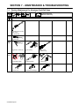
SECTION 7 − MAINTENANCE & TROUBLESHOOTING 22...........................................
7-1. Routine Maintenance For Aluminum Push/Pull Guns 22........................................
7-2. Cleaning The Gun Liner On XR-Aluma-Pro Guns 23...........................................
7-3. Troubleshooting Table 24.................................................................
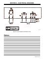
SECTION 8 − ELECTRICAL DIAGRAMS 25........................................................
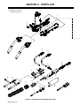
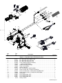
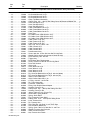
SECTION 9 − PARTS LIST 26.....................................................................
SECTION 10 − PARTS LIST INCLUDING CONSUMABLES 31........................................
WARRANTY

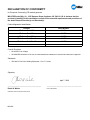
DECLARATION OF CONFORMITY
for European Community (CE marked) products.
MILLER Electric Mfg. Co., 1635 Spencer Street, Appleton, WI 54914 U.S.A. declares that the
product(s) identified in this declaration conform to the essential requirements and provisions of
the stated Council Directive(s) and Standard(s).
Product/Apparatus Identification:
Product
Stock Number
XR‐Aluma‐Prot15W 301571
XR‐Aluma‐Prot25W 301572
XR‐Aluma‐Prot35W 301573
XR‐W Aluma‐ProtPlus 15 301576
XR‐W Aluma‐ProtPlus 25 301577
Council Directives:
• 2014/35/EU Low Voltage
• 2015/865/EU Restriction of the use of certain hazardous substances in electrical and electronic equipment
Standards:
• IEC 609747:2013 Arc Welding Equipment – Part 7: Torches
Signatory:
_____________________________________ ___________________________________________
David A. Werba Date of Declaration
MANAGER, PRODUCT DESIGN COMPLIANCE
April 7, 2020
287835A

OM-285556 Page 1
SECTION 1 −SAFETY PRECAUTIONS FOR GMAW
WELDING GUNS − READ BEFORE USING
SR7 (MIG) 2020-02
Protect yourself and others from injury — read, follow, and save these important safety precautions and operating instructions.
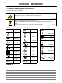
1-1. Symbol Usage
DANGER! − Indicates a hazardous situation which, if
not avoided, will result in death or serious injury. The
possible hazards are shown in the adjoining symbols
or explained in the text.
Indicates a hazardous situation which, if not avoided,
could result in death or serious injury. The possible
hazards are shown in the adjoining symbols or ex-
plained in the text.
NOTICE − Indicates statements not related to personal injury.
. Indicates special instructions.
This group of symbols means Warning! Watch Out! ELECTRIC
SHOCK, MOVING PARTS, and HOT PARTS hazards. Consult sym-
bols and related instructions below for necessary actions to avoid
these hazards.
1-2. Arc Welding Hazards
The symbols shown below are used throughout this manual
to call attention to and identify possible hazards. When you
see the symbol, watch out, and follow the related instructions
to avoid the hazard. The safety information given below is
only a summary of the more complete safety information
found in the Principal Safety Standards listed in Section 1-4,
and in welding power source Owner’s Manual. Read and fol-
low all Safety Standards.
Only qualified persons should install, operate, maintain, and
repair this equipment. A qualified person is defined as one
who, by possession of a recognized degree, certificate, or
professional standing, or who by extensive knowledge, train-
ing and experience, has successfully demonstrated ability to
solve or resolve problems relating to the subject matter, the
work, or the project and has received safety training to recog-
nize and avoid the hazards involved.
During operation, keep everybody, especially children, away.
ELECTRIC SHOCK can kill.
D Always wear dry insulating gloves.
D Insulate yourself from work and ground.
D Do not touch live electrode or electrical parts.
D Replace worn, damaged, or cracked guns or cables.
D Turn off welding power source before changing contact tip or gun
parts.
D Keep all covers and handle securely in place.
FUMES AND GASES can be hazardous.
D Keep your head out of the fumes.
D Ventilate area, or use breathing device. The
recommended
way to determine adequate
ventilation
is to sample for the composition and quantity of fumes
and gases to which personnel are exposed.
D Read and understand the Safety Data Sheets (SDSs) and the
manufacturer’s instructions for adhesives, coatings, cleaners,
consumables, coolants, degreasers, fluxes, and metals.
MOVING PARTS can injure.
D Keep away from moving parts.
D Keep away from pinch points such as drive
rolls.
WELDING can cause fire or explosion.
D Do not weld near flammable material.
D Do not weld on containers that have held com-
bustibles, or on closed containers such as
tanks, drums, or pipes unless they are properly prepared ac-
cording to AWS F4.1 and AWS A6.0 (see Safety Standards).
D Watch for fire; keep extinguisher nearby.
D Read and understand the Safety Data Sheets (SDSs) and the
manufacturer’s instructions for adhesives, coatings, cleaners,
consumables, coolants, degreasers, fluxes, and metals.
BUILDUP OF GAS can injure or kill.
D Shut off compressed gas supply when not in
use.
D Always ventilate confined spaces or use ap-
proved air-supplied respirator.
Arc rays from the welding process produce intense
visible and invisible (ultraviolet and infrared) rays
that can burn eyes and skin. Sparks fly off from the
weld.
ARC RAYS can burn eyes and skin.
D Wear an approved welding helmet fitted with a proper shade of filter
lenses to protect your face and eyes from arc rays and sparks
when welding or watching (see ANSI Z49.1 and Z87.1 listed in
Safety Standards).
D Wear approved safety glasses with side shields under your
helmet.
D Use protective screens or barriers to protect others from flash,
glare and sparks; warn others not to watch the arc.
D Wear body protection made from durable, flame-resistant material
(leather, heavy cotton, wool). Body protection includes oil-free
clothing such as leather gloves, heavy shirt, cuffless trousers, high
shoes, and a cap.
HOT PARTS can burn.
D Allow gun to cool before touching.
D Do not touch hot metal.
D Protect hot metal from contact by others.

OM-285556 Page 2
NOISE can damage hearing.
Noise from some processes or equipment can
damage hearing.
D Check for noise level limits exceeding those
specified by OSHA.
D Use approved ear plugs or ear muffs if noise level is high.
D Warn others nearby about noise hazard.
WELDING WIRE can injure.
D Keep hands and body away from gun tip when
trigger is pressed.
READ INSTRUCTIONS.
D Read and follow all labels and the Owner’s
Manual carefully before installing, operating, or
servicing unit. Read the safety information at
the beginning of the manual and in each
section.
D Use only genuine replacement parts from the manufacturer.
D Perform installation, maintenance, and service according to the
Owner’s Manuals, industry standards, and national, state, and
local codes.
1-3. California Proposition 65 Warnings
WARNING: This product can expose you to chemicals in-
cluding lead, which are known to the state of California to
cause cancer and birth defects or other reproductive
harm.
For more information, go to www.P65W
arnings.ca.gov
.
1-4. Principal Safety Standards
Safety in Welding, Cutting, and Allied Processes, American Welding
Society standard ANSI Standard Z49.1. Website: www.aws.org.
Safe Practice For Occupational And Educational Eye And Face Protec-
tion, ANSI Standard Z87.1 from American National Standards Institute.
Website: www.ansi.org.
Safe Practices for the Preparation of Containers and Piping for Welding
and Cutting, American Welding Society Standard AWS F4.1 from Glob-
al Engineering Documents. Website: www
.global.ihs.com.
Safe Practices for Welding and Cutting Containers that have Held Com-
bustibles, American Welding Society Standard AWS A6.0 from Global
Engineering Documents. Website: www.global.ihs.com.
National Electrical Code, NFPA Standard 70 from National Fire Protection
Association. Website: www.nfpa.org and www. sparky.org.
Safe Handling of Compressed Gases in Cylinders, CGA Pamphlet P-1,
from Compressed Gas Association. Website:www.cganet.com.
Safety in Welding, Cutting, and Allied Processes, CSA Standard
W117.2 from Canadian Standards Association.
Website: www.csagroup.org.
Standard for Fire Prevention During Welding, Cutting, and Other Hot
Work, NFPA Standard 51B from National Fire Protection Association.
Website: www.nfpa.org.
OSHA Occupational Safety and Health Standards for General Industry,
Title 29, Code of Federal Regulations (CFR), Part 1910.177 Subpart N, Part
1910 Subpart Q, and Part 1926, Subpart J. Website: www.osha.gov.
1-5. EMF Information
Electric current flowing through any conductor causes localized electric
and magnetic fields (EMF). The current from arc welding (and allied pro-
cesses including spot welding, gouging, plasma arc cutting, and induc-
tion heating operations) creates an EMF field around the welding circuit.
EMF fields can interfere with some medical implants, e.g. pacemakers.
Protective measures for persons wearing medical implants have to be
taken. For example, restrict access for passers−by or conduct individu-
al risk assessment for welders. All welders should use the following pro-
cedures in order to minimize exposure to EMF fields from the welding
circuit:
1. Keep cables close together by twisting or taping them, or using a
cable cover.
2. Do not place your body between welding cables. Arrange cables
to one side and away from the operator.
3. Do not coil or drape cables around your body.
4. Keep head and trunk as far away from the equipment in the
welding circuit as possible.
5. Connect work clamp to workpiece as close to the weld as
possible.
6. Do not work next to, sit or lean on the welding power source.
7. Do not weld whilst carrying the welding power source or wire
feeder.
About Implanted Medical Devices:
Implanted Medical Device wearers should consult their doctor and the
device manufacturer before performing or going near arc welding, spot
welding, gouging, plasma arc cutting, or induction heating operations.
If cleared by your doctor, then following the above procedures is recom-
mended.

OM-285556 Page 3
SECTION 2 − MESURES DE SÉCURITÉ VISANT LES
PISTOLETS DE SOUDAGE GMAW − À LIRE AVANT
UTILISATION
SR7(MIG)_2020−02_fre
Pour écarter les risques de blessure pour vous−même et pour autrui — lire, appliquer et ranger en lieu sûr ces consignes relatives
aux précautions de sécurité et au mode opératoire.
2-1. Signification des symboles
DANGER! − Indique une situation dangereuse qui si on
l’évite pas peut donner la mort ou des blessures graves.
Les dangers possibles sont montrés par les symboles
joints ou sont expliqués dans le texte.
Indique une situation dangereuse qui si on l’évite pas
peut donner la mort ou des blessures graves. Les dan-
gers possibles sont montrés par les symboles joints ou
sont expliqués dans le texte.
AVIS − Indique des déclarations pas en relation avec des blessures
personnelles.
. Indique des instructions spécifiques.
Ce groupe de symboles veut dire Avertissement! Attention! DANGER
DE CHOC ELECTRIQUE, PIECES EN MOUVEMENT, et PIECES
CHAUDES. Reportez−vous aux symboles et aux directives
ci−dessous afin de connaître les mesures à prendre pour éviter tout
danger.
2-2. Dangers relatifs au soudage à l’arc
Les symboles présentés ci-après sont utilisés tout au long du
présent manuel pour attirer votre attention et identifier les ris-
ques de danger. Lorsque vous voyez un symbole, soyez vigilant
et suivez les directives mentionnées afin d’éviter tout danger.
Les consignes de sécurité présentées ci−après ne font que rés-
umer les informations contenues dans les principales normes
de sécurité énumérées à la section 2-4 et manuel d’utilisation
du poste de soudage. Veuillez lire et respecter toutes ces
normes de sécurité.
L
’installation,
l’utilisation, l’entretien et les réparations ne
doivent être confiés qu’à des personnes qualifiées. Une per-
sonne qualifiée est définie comme celle qui, par la posses-
sion d’un diplôme reconnu, d’un certificat ou d’un statut pro-
fessionnel, ou qui, par une connaissance, une formation et
une expérience approfondies, a démontré avec succès sa ca-
pacité à résoudre les problèmes liés à la tâche, le travail ou
le projet et a reçu une formation en sécurité afin de recon-
naître et d’éviter les risques inhérents.
Au cours de l’utilisation, tenir toute personne à l’écart et plus
particulièrement
les enfants.
UN CHOC ÉLECTRIQUE peut tuer.
D Porter toujours des gants secs et isolants.
D S’isoler de la pièce et de la terre.
D Ne jamais toucher une électrode ou des pièces
électriques
sous tension.
D Remplacer les pistolets ou câbles de soudage qui sont endom-
magés, usés ou craquelés.
D Mettre la soudeuse hors tension avant de remplacer un bec
contact ou des pièces de pistolet.
D S’assurer que tous les couvercles et poignées sont fermement
assujettis.
LES VAPEURS ET LES FUMÉES
peuvent être nocives.
D Éloigner sa tête des endroits renfermant des
vapeurs.
D Aérer la zone de travail ou porter un appareil respiratoire. Pour dé-
terminer la bonne ventilation, il est recommandé de procéder à un
prélèvement
pour la composition et la quantité de fumées et de gaz
auxquels est exposé le personnel.
D Lire et comprendre les fiches de données de sécurité et les instruc-
tions du fabricant concernant les adhésifs, les revêtements, les net-
toyants, les consommables, les produits de refroidissement, les
dégraisseurs,
les flux et les métaux.
LE SOUDAGE peut causer un in-
cendie ou une explosion.
D Ne pas souder à proximité de matériaux inflam-
mables.
D Ne pas effectuer le soudage sur des conteneurs fermés tels que
des réservoirs, tambours, ou conduites, à moins qu’ils n’aient été
préparés correctement conformément à AWS F4.1 et AWS A6.0
(voir les Normes de Sécurité).
D Prendre garde aux incendies et toujours avoir un extincteur à
proximité.
D Lire et comprendre les fiches de données de sécurité et les
instructions du fabricant concernant les adhésifs, les revêtements,
les nettoyants, les consommables, les produits de refroidissement,
les dégraisseurs, les flux et les métaux.
L’ACCUMULATION DE VAPEURS
peut causer des lésions ou la mort.
D Quand on n’utilise pas le gaz comprimé de pro-
tection, fermer le robinet de la bouteille.
D Assurer toujours la ventilation des zones fermées ou utiliser un
appareil respiratoire avec alimentation en air.
Les PIÈCES MOBILES peuvent
causer des blessures.
D Ne pas s’approcher des organes mobiles.
D Ne pas s’approcher des points de coincement
tels que des rouleaux de commande.
LE RAYONNEMENT DE L’ARC peut
brûler les yeux et la peau.
Le rayonnement de l’arc du procédé de soudage
génère des rayons visibles et invisibles intenses
(ultraviolets et infrarouges) susceptibles de provoquer des brûlures
dans les yeux et sur la peau. Des étincelles sont projetées pendant le
soudage.
D Porter un casque de soudage approuvé muni de verres filtrants
approprié pour protéger visage et yeux pendant le soudage
(voir ANSI Z49.1 et Z87.1 énuméré dans les normes de sécurité).
D Porter des lunettes de sécurité avec écrans latéraux même sous
votre casque.

OM-285556 Page 4
D Avoir recours à des écrans protecteurs ou à des rideaux pour
protéger les autres contre les rayonnements les éblouissements
et les étincelles ; prévenir toute personne sur les lieux de ne pas
regarder l’arc.
D Porter un équipement de protection pour le corps fait d’un matériau
résistant et ignifuge (cuir, coton robuste, laine). La protection du
corps comporte des vêtements sans huile comme par ex. des
gants de cuir, une chemise solide, des pantalons sans revers, des
chaussures hautes et une casquette.
LES PIÈCES CHAUDES peuvent
provoquer des brûlures.
D Laisser refroidir le pistolet avant de le toucher.
D Ne pas toucher d’objets métalliques chauds.
D Abriter les objets métalliques contre tout
contact par les personnes à proximité.
Le BRUIT peut endommager l’ouie.
Le bruit des processus et des équipements peut
affecter l’ouïe.
D Vérifier si les niveaux de bruit excèdent les lim-
ites spécifiées par l’OSHA.
D Utiliser des bouche-oreilles ou des serre-tête antibruit approuvés si
le niveau de bruit est élevé.
D Avertir les personnes à proximité au sujet du danger inhérent au
bruit.
LES FILS DE SOUDAGE peuvent
provoquer des blessures.
D Éloigner les mains et le corps de la buse du
pistolet après avoir appuyé sur la gâchette.
LIRE LES INSTRUCTIONS.
D Lire et appliquer les instructions sur les
étiquettes
et le Mode d’emploi avant
l’installation,
l’utilisation ou l’entretien de
l’appareil.
Lire les informations de sécurité au
début du manuel et dans chaque section.
D N’utiliser que les pièces de rechange recommandées par le cons-
tructeur.
D Effectuer l’installation, l’entretien et toute intervention selon les
manuels d’utilisateurs, les normes nationales, provinciales et de
l’industrie,
ainsi que les codes municipaux.
2-3. Proposition californienne 65 Avertissements
AVERTISSEMENT : ce produit peut vous exposer à des
produits chimiques tels que le plomb, reconnus par l’État de
Californie comme cancérigènes et sources de malformations
ou d’autres troubles de la reproduction.
Pour plus d’informations, consulter www.P65W
arnings.ca.gov
.
2-4. Principales normes de sécurité
Safety in Welding, Cutting, and Allied Processes, American Welding
Society standard ANSI Standard Z49.1. Website: www.aws.org.
Safe Practice For Occupational And Educational Eye And Face Protec-
tion, ANSI Standard Z87.1 from American National Standards Institute.
Website: www.ansi.org.
Safe Practices for the Preparation of Containers and Piping for Welding
and Cutting, American Welding Society Standard AWS F4.1 from Glob-
al Engineering Documents. Website: www
.global.ihs.com.
Safe Practices for Welding and Cutting Containers that have Held Com-
bustibles, American Welding Society Standard AWS A6.0 from Global
Engineering Documents. Website: www.global.ihs.com.
National Electrical Code, NFPA Standard 70 from National Fire Protection
Association. Website: www.nfpa.org and www. sparky.org.
Safe Handling of Compressed Gases in Cylinders, CGA Pamphlet P-1,
from Compressed Gas Association. Website:www.cganet.com.
Safety in Welding, Cutting, and Allied Processes, CSA Standard
W117.2 from Canadian Standards Association.
Website: www.csagroup.org.
Standard for Fire Prevention During Welding, Cutting, and Other Hot
Work, NFPA Standard 51B from National Fire Protection Association.
Website: www.nfpa.org.
OSHA Occupational Safety and Health Standards for General Industry,
Title 29, Code of Federal Regulations (CFR), Part 1910.177 Subpart N, Part
1910 Subpart Q, and Part 1926, Subpart J. Website: www.osha.gov.
2-5. Informations relatives aux CEM
Le courant électrique qui traverse tout conducteur génère des champs
électromagnétiques (CEM) à certains endroits. Le courant de soudage
crée un CEM autour du circuit et du matériel de soudage. Le courant
issu d’un soudage à l’arc (et de procédés connexes, y compris le
soudage par points, le gougeage, le découpage plasma et les
opérations
de chauffage par induction) crée un champ
électromagnétique
(CEM) autour du circuit de soudage. Les champs
électromagnétiques
produits peuvent causer interférence à certains
implants médicaux, p. ex. les stimulateurs cardiaques. Des mesures de
protection pour les porteurs d’implants médicaux doivent être prises:
Limiter par exemple tout accès aux passants ou procéder à une
évaluation
des risques individuels pour les soudeurs. Tous les
soudeurs doivent appliquer les procédures suivantes pour minimiser
l’exposition aux CEM provenant du circuit de soudage:
1 Rassembler les câbles en les torsadant ou en les attachant avec
du ruban adhésif ou avec une housse.
2 Ne pas se tenir au milieu des câbles de soudage. Disposer les
câbles d’un côté et à distance de l’opérateur.
3 Ne pas courber et ne pas entourer les câbles autour de votre
corps.
4 Maintenir la tête et le torse aussi loin que possible du matériel du
circuit de soudage.
5 Connecter la pince sur la pièce aussi près que possible de la
soudure.
6 Ne pas travailler à proximité d’une source de soudage, ni
s’asseoir ou se pencher dessus.
7 Ne pas souder tout en portant la source de soudage ou le
dévidoir.
En ce qui concerne les implants médicaux :
Les porteurs d’implants doivent d’abord consulter leur médecin avant
de s’approcher des opérations de soudage à l’arc, de soudage par
points, de gougeage, du coupage plasma ou de chauffage par
induction. Si le médecin approuve, il est recommandé de suivre les pro-
cédures précédentes.

OM-285556 Page 5
SECTION 3 − DEFINITIONS
3-1. Additional Safety Symbols And Definitions
. Some symbols are found only on CE products.
Warning! Watch Out! There are possible hazards as shown by the symbols.
Safe1 2012−05
Do not discard product (where applicable) with general waste.
Reuse or recycle Waste Electrical and Electronic Equipment (WEEE) by disposing at a designated collection
facility.
Contact your local recycling office or your local distributor for further information.
Safe37 2017−04
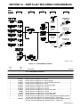
3-2. Miscellaneous Symbols And Definitions
V
Volts
Alternating
Cur-
rent
X
Duty Cycle
Wire Feed
Gun
Trigger Hold Off
Run-In
Read Instructions
Water (Coolant)
Input
A
Amperes
Circuit Breaker
Trigger
Trigger Hold On
Percent
U
2
Load Voltage
Line Connection
Continuous
Spot Welding
Hz
Hertz
Output
Increase
Spot Weld Time
U
1
Primary Voltage
I
2
Rated Current
Fuse
IP
Degree Of
Protection
Jog
Press To Set
Purge
Burnback Time
I
1
Primary Current
Water (Coolant)
Output
Notes

OM-285556 Page 6
SECTION 4 − SPECIFICATIONS
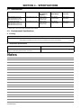
4-1. Specifications
Model Welding Output Range Electrode
Wire Diameter
Capacity
Wire Feed
Speed Range
Net Weight
(Torch Only)
XR-A Aluma-Pro 15 ft (4.7 m)
XR-A Aluma-Pro 25 ft (7.6 m)
XR-A Aluma-Pro 35 ft (10.7 m)
300 A at 100% Duty Cycle .030 To 1/16 in.
(0.8 To 1.6 mm)
aluminum wire
70 To 900 ipm
(1.8 To 23 mpm)
2.2 lb (1.0 kg)
(less cables)
(CE And Non CE Models)
XR-W Aluma-Pro 15 ft (4.7 m)
XR-W Aluma-Pro 25 ft (7.6 m)
XR-W Aluma-Pro 35 ft (10.7 m)
400 A at 100% Duty Cycle .030 To 1/16 in.
(0.8 To 1.6 mm)
aluminum wire
70 To 900 ipm
(1.8 To 23 mpm)
2.2 lb (1.0 kg)
(less cables)
. When using 1/16 in (1.6 mm) wire, kit 230708 must be installed.
4-2. Environmental Specifications
A. IP Rating
IP Rating
IP3X
This equipment is designed for indoor use and is not intended to be used or stored outside.
IP3X 2014−06
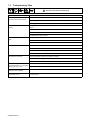
B. Temperature Specifications
Operating Temperature Range* Storage/Transportation Temperature Range
14 to 104°F (−10 to 40°C)
*Output is derated at temperatures above 104°F (40°C).
−4 to 131°F (−20 to 55°C)
Temp1_016-08
Notes

OM-285556 Page 7
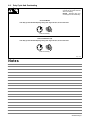
4-3. Duty Cycle And Overheating
Duty Cycle is percentage of 10 min-
utes that unit can weld at rated load
without overheating.
NOTICE − Exceeding duty cycle
can damage unit and void warranty.
sduty1 5/95
Air-Cooled Models
Continuous Welding
100% Duty Cycle At 300 Peak Amperage Using 100% Argon Gas w/15, 25 Or 35 Foot Guns
Water-Cooled Models (CE)
Continuous Welding
100% Duty Cycle At 400 Peak Amperage Using 100% Argon Gas w/15, 25 Or 35 Foot Guns
Notes

OM-285556 Page 8
SECTION 5 − INSTALLATION
. Be sure that contact tip, liner, and drive rolls are correct for wire size and type. See Parts List to change parts as needed.
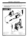
5-1. Connections With A Constant Current (CC), Constant Voltage (CV) Or Constant
Current/Constant Voltage (CC/CV) Welding Power Source Having A
14-Socket Receptacle
Ref. 285602-A / 285544-A
1 CC, CV Or CC/CV Welding Power
Source
2 24 VAC/Contactor Control 14-Pin
Plug
3 Negative (−) Weld Cable
4 Workpiece
5 Welding Gun
6 Wire Feeder
7 24 VAC/Contactor Control Cord
8 Positive (+) Weld Cable
9 Gas Cylinder
. Shielding gas pressure not to exceed
100 psi (689 kPa).
4
Millermatic 350P
XR-D
5
1
9
5
1
2
6
9
3
8
7

OM-285556 Page 9
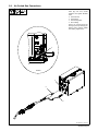
5-2. Air-Cooled Gun Connections
Ref. 285545-A / 246218-A
1 Gun Control Cable
Insert plug into Gun Control
receptacle, and tighten threaded
collar.
2 Gun Power Pin
3 Gun Bushing
4 Gun Securing Knob
5 Drive Casting
Loosen gun securing knob and
insert gun power pin through gun
bushing until it bottoms against
drive casting. Tighten knob.
5
4
1
Left Side
2
3

OM-285556 Page 10
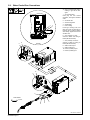
5-3. Water-Cooled Gun Connections
Ref. 285546-A / 246218-A
. Turn on coolant supply before
welding or gun will be dam-
aged.
1 Gun Control Cable
Insert plug into Gun Control
receptacle, and tighten threaded
collar.
2 Gun Power Pin
3 Gun Securing Knob
4 Gun Bushing
5 Drive Casting
Loosen gun securing knob, and
insert gun power pin through gun
bushing until it bottoms against
drive casting. Tighten knob. Close
and latch door.
6 Gun (Coolant) “In” Hose
Connect to Water “Out” fitting on
feeder (left-hand threads).
7 Gun (Coolant) “Out” Hose
Connect to Water “In” fitting on
feeder (left-hand threads)
8 Water Cooler Output
9 Water Cooler Input
10 Feeder (Coolant) Output
11 Feeder (Coolant) Input
Tools Needed:
1
6
7
9/16 in.
5
3
Left Side
8
9
10
11
2
4
4

OM-285556 Page 11
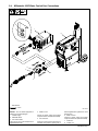
5-4. Millermatic 350P Water Cooled Gun Connections
Ref. 285547-A
NOTICE − Turn on coolant supply before
welding or gun will be damaged.
1 Coolant Supply
2 Millermatic 350P
3 Gun Control Cable
Insert plug into gun control receptacle and
tighten threaded collar.
4 Water In Hose
Connect to coolant supply with supplied
coupler and water hose (left-hand threads).
5 Gun Connector
Loosen gun securing knob, and insert gun
connector through Wire opening until it
bottoms against block. Tighten knob. Close
and latch door.
6 Water Out Hose
Connect to coolant supply with supplied
coupler and water hose (left-hand threads).
7 Coolant “In”
8 Coolant “Out”
Tools Needed:
5
9/16 in.
6
4
3
1
2
8
7

OM-285556 Page 12
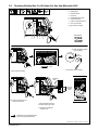
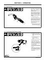
5-5. Threading Welding Wire For XR-Aluma-Pro Gun And Millermatic 350P
1 Wire Spool
2 Welding Wire
3 Inlet Wire Guide
4 Drive Roll
5 Intermediate Wire Guide
6 Outlet Wire Guide
7 Pressure Adjustment Knob
8 Gun Conduit Cable
Lay gun cable out straight.
Tools Needed:
6 in.
(150 mm)
. Hold wire tightly to keep it
from unraveling.
Open pressure assembly.
Pull and hold wire; cut off end.
Push wire thru guides into gun;
continue to hold wire.
Close and tighten pressure
assembly, and let go of wire.
. Set pressure indicator
scale to 1/2 lb.
Ref. 803544-A / 218243-A / 218244-A / S-0627-A
1
2
3
4
Pressure
Indicator
Scale
218243-A
IMPORTANT!
For Aluminum Push-Pull welding.
Thread hub tension nut loosely
IMPORTANT!
For Aluminum
Push-Pull welding.
1
2
3
4
218244-A
7
8
35621 4
See Section 5-10 for threading weld-
ing wire through AlumaPro guns.
3/4 in.
Tighten to
1/2 lb.

OM-285556 Page 13
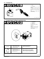
5-6. Threading Welding Wire Through XR-Control Feeder
Ref. 246218-A / 805354
Tools Needed:
2
1
1 Cable Assembly
Lay cable assembly out straight.
2 Jog Switch
Push Jog switch up to feed wire through
cable assembly.
3 Torque Switch
. Select proper push feeder torque set-
ting for wire size being used. Use low
torque for .030 in. (0.8mm) wire. Use
high torque for all other wire sizes.
. XR-AlumaFeed torque setting is auto-
matically set internally for wire sizes.
3
JOG / PURGE
Notes

OM-285556 Page 14
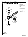
5-7. Adjusting Tension At Feeder
Ref. 805350-A / 242517-A
Tools Needed:
Pull and hold wire; cut off end.
6 in.
(150 mm)
1 Tension Arm
Open tension arm.
Thread wire thru inlet guide, along drive roll groove, and
into wire conduit. Close tension arm. Adjust tension as
follows:
. Hold wire tightly to keep
it from unraveling.
1
1
Wire Size Welding Gun Calibration
3−4
3−4
1−2
0.035 in.
0.040 in.
3/64 in.
1/16 in.
Tension Settings
Install proper size drive rolls.

OM-285556 Page 15
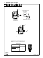
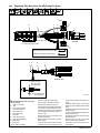
5-8. 10-Pin Plug Information
10
Pin* Pin Information
E
F
D
J
G
C
I
H
B
A
A Electrode sense lead
B Motor Common
G Trigger
C Motor 0 to +24 volts DC with respect to pin B
D Trigger
E Wire speed Ref. +9 volts DC
H Wire speed com
F Wire speed 0 to +9 volts DC with respect to pin H
J Gun sensing resistor with respect to pin H
I Not used
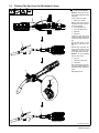
5-9. Opening Top Cover Of XR-Aluma-Pro Gun
1 Top Cover
Squeeze sides of cover and lift up
as shown.
To close cover, pivot cover closed
on gun, and push cover down until
cover locks tight.
Ref. 285542-A
1

OM-285556 Page 16
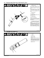
! Welding wire is electrically live when
gun trigger is used to jog wire.
. Refer to Section 5-6 for instructions on feeding
wire through feeder.
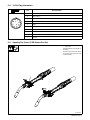
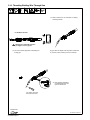
5-10. Threading Welding Wire Through Gun
Ref. 285542-A / 285543-A
Tools Needed:
Lay gun cable out straight. Press Jog switch until about 6
in. (152 mm) of wire is sticking out end of contact tip.
Cut off wire. Close and
latch wire feeder door.
. Turn OFF coolant supply before threading wire
through gun..
For XR-Aluma-Pro Gun:
. Verify pressure adjustment
on handle matches the wire
type. See Section 6-2.
JOG / PURGE
La page est en cours de chargement...
La page est en cours de chargement...
La page est en cours de chargement...
La page est en cours de chargement...
La page est en cours de chargement...
La page est en cours de chargement...
La page est en cours de chargement...
La page est en cours de chargement...
La page est en cours de chargement...
La page est en cours de chargement...
La page est en cours de chargement...
La page est en cours de chargement...
La page est en cours de chargement...
La page est en cours de chargement...
La page est en cours de chargement...
La page est en cours de chargement...
La page est en cours de chargement...
La page est en cours de chargement...
La page est en cours de chargement...
La page est en cours de chargement...
-
 1
1
-
 2
2
-
 3
3
-
 4
4
-
 5
5
-
 6
6
-
 7
7
-
 8
8
-
 9
9
-
 10
10
-
 11
11
-
 12
12
-
 13
13
-
 14
14
-
 15
15
-
 16
16
-
 17
17
-
 18
18
-
 19
19
-
 20
20
-
 21
21
-
 22
22
-
 23
23
-
 24
24
-
 25
25
-
 26
26
-
 27
27
-
 28
28
-
 29
29
-
 30
30
-
 31
31
-
 32
32
-
 33
33
-
 34
34
-
 35
35
-
 36
36
-
 37
37
-
 38
38
-
 39
39
-
 40
40


Miller XR-ALUMAPRO Le manuel du propriétaire
- Catégorie
- Système de soudage
- Taper
- Le manuel du propriétaire
- Ce manuel convient également à
dans d''autres langues
- English: Miller XR-ALUMAPRO Owner's manual
Documents connexes
-
Miller MF220315T Le manuel du propriétaire
-
-
-
-
-
-
-
-
-
Miller XR-ALUMAPRO Le manuel du propriétaire