Winco NGSP-1 Manuel utilisateur
- Catégorie
- Plaques électriques
- Taper
- Manuel utilisateur

Model
Burner(s) Ring(s)
BTU/
Burner
Total
BTU/HR
Pressure
IN. W.C
Orice
Size
Overall Dimensions
Weight
NGSP-1 2 3 40,000 80,000 5 / 10
Nat #32
(3.0mm)
Width Depth
Height
101 Lbs
(46 Kg)
17.9"
(454.6mm)
21.38"
(543mm)
25.7"
(652.7mm)
LP #47
(2.0mm)
Grate Surface
17.69"
(449.3mm)
21.38"
(543mm)
Note: Depths do not include gas inlet pipe, located at rear of the unit.
GAS EQUIPMENT, NATURAL / LP
STOCK POT STOVE
Operating Instruction Manual
BEFORE OPERATING ANY EQUIPMENT, READ AND FAMILIARIZE YOURSELF WITH THESE USE AND SAFETY INSTRUCTIONS
Congratulations on your purchase of this SPECTRUM
TM
stock pot stove. When used as intended, and with proper care and maintenance,
you are sure to experience years of reliable operation from this equipment. To ensure best results, it is important that you read and follow
the instructions in this manual carefully. It is important to keep these instructions in a safe place for future reference.
NGSP-1
Form No. NGSP-1 Manual - 042919
SANITATION

2
GAS STOCK POT STOVE
Important For Future Reference
GAS PRESSURE
The appliance and its individual shuto valve (to be supplied by
user) must be disconnected from the gas supply piping system
during any pressure testing of that system at test pressures in
excess of ½ psi (3.45 kPa).
The appliance must be isolated from the gas supply piping
system by closing its individual manual shut-o valve during any
pressure testing of the gas supply piping system at test pressures
equal to or less than ½ psi (3.45 kPa).
PRESSION DE GAZ
L'appareil et la vanne d'arrêt individuel (à fournir par
l'utilisateur) doit être débranchés de la tuyauterie d'alimentation
en gaz pendant tout test de pression de ce système à des
pressions d' essai supérieures à ½ psi (3.45 kPa).
L'appareil doit être isolé du système de conduites d'alimentation
en gaz en fermant son robinet manuel d'arrêt individuel durant
tout test de pression du système de tuyauterie d'alimentation en
gaz à des pressions inférieures à ½ psi (3.45 kPa).
Please complete this information and retain this manual for the life of the equipment. For
Warranty Service and/or parts, this information is required.
Model Number Serial Number Date Purchased
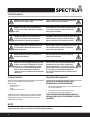
! !
WARNING: Improper installation, adjustment,
alteration, service or maintenance can cause property
damage, injury, or death. Read the installation
operating and maintenance instructions thoroughly
before installing, or servicing this equipment.
AVERTISSEMENT: Une installation, un réglage, une
modication, un entretien ou peut causer des dommages
matériels, des blessures ou la mort. Lisez les
instructions d' exploitation et de maintenance d'installation
avant d'installer, ou sauvegarder cet équipement.
! !
WARNING: Instructions must be posted in a prominent
location. All safety precautions must be taken in the
event the user smells gas. Safety information can be
obtained from your local gas supplier.
AVERTISSEMENT: Les instructions doit être achées dans
un endroit bien en vue. Toutes les mesures de sécurité
doit être prises en cas d'odeur de gaz. Les consignes
de sécurité peut être obtenue auprès de votre fournisseur
de gaz local.
! !
WARNING: A factory authorized agent should handle
all maintenance and repair. Before doing any
maintenance or repair, contact your authorized service
representative.
AVERTISSEMENT: Un agent autorisé de l'usine doit traiter
tout l'entretien et la réparation. Avant de faire tout
entretien ou réparation, contactez votre représentant
de service autorisé.
! !
CAUTION: These models are designed, built, and sold for
commercial use only. If these models are positioned so
the general public can use the equipment, make sure
that cautions, warnings, and operating instructions
are clearly posted near each unit so that anyone using
the equipment will use it correctly and not injure
themselves or harm the equipment.
ATTENTION: Ces modèles sont conçus, fabriqués et vendus
pour un usage commercial seulement. Si ces modèles
sont positionnés de sorte que le grand public peut
utiliser l'équipement, assurez-vous que mises en garde, les
avertissements et les instructions sont clairement achés unité
de sorte que toute personne utilisant l'équipement va l'utiliser
correctement et de ne pas nuire à injurethemselves
ou l'équipement.
! !
WARNING: For your safety, do not store or use gasoline
or other ammable vapors or liquids in the vicinity of
this or any other appliances. Keep the area free and
clear of combustibles. (See ANSI Z83. 14B, 1991).
AVERTISSEMENT: Pour votre sécurité, ne pas stocker ni
utiliser d'essence ou d'autres vapeurs ou liquides
inammables à proximité de cet appareil ou d'autres
appareils. Garder la zone libre de combustible.
(Voir la norme ANSI Z83. 14B, 1991).

3
GAS STOCK POT STOVE
Table of Contents
Specications ................................................................................................. 1
Warnings ........................................................................................................2
Introduction ..................................................................................................3
Safety Precautions ........................................................................................4
Packaging ......................................................................................................4
Installation .....................................................................................................5
Conversion .....................................................................................................7
Lighting Pilot .................................................................................................8
Operation .......................................................................................................9
Cleaning, Care & Maintenance ...................................................................9
Safety ..............................................................................................................9
Troubleshooting .........................................................................................10
Service & Repair .......................................................................................... 10
Exploded View ............................................................................................ 11
Spare Parts List ...........................................................................................11
Limited Warranty ........................................................................................12
Introduction
Congratulations on the purchase of your SPECTRUM™ machine. Please take
time to carefully read through this manual to ensure the machine is operated
and maintained properly, to ensure the best possible performance from the
product for many years.
SPECTRUM will not accept liability for the following if:
• The instructions in this manual have not been followed correctly.
• Non-authorized personnel have tampered with the machine.
• Non-original spare parts are used.
• The machine has not been handled and cleaned correctly.
• There is any use damage to the unit.
LOCATION OF DATA PLATE
The data plate is located on the rear or side panel.
IMMEDIATELY INSPECT FOR SHIPPING DAMAGE
All containers should be examined for damage before and during unloading.
The freight carrier has assumed responsibility for its safe transit and delivery.
If equipment is received damaged, either apparent or concealed, a claim
must be made with the delivering carrier.
A. Apparent damage or loss must be noted on the freight bill at the time of
delivery. It must then be signed by the carrier representative (Driver). If
this is not done, the carrier may refuse the claim. The carrier can supply
the necessary forms.
B. If concealed damage or loss is not apparent until after equipment is
uncrated, a request for inspection must be made to the carrier within
15 days. The carrier should arrange an inspection. Be certain to keep all
contents and packaging material.
Installation should be performed by a qualied installer who thoroughly
read, understands and follows these instructions.
If you have questions concerning the installation, operation, maintenance or
service of this product, please contact WINCO®.
Please keep this manual in a safe place for future use!

4
Package Contents
All units come with Installation & Operation Instructions
and the following:
• (1) Stock Pot Stove Set
• (1) Grease Tray
• (4) Legs
• (1) Natural to LP Gas Conversion
SPECTRUM™ prides itself on quality and service, ensuring that at the time
of packing, all products are supplied fully functional and free of damage.
Should you nd any damage as a result of freight, please contact your
SPECTRUM dealer immediately.
Unpacking the Equipment
DISPOSE OF ALL PACKAGING MATERIALS IN AN
ENVIRONMENTALLY RESPONSIBLE MANNER.
1. Remove all packing materials and tape, as well as any protective plastic
and cardboard, from the unit.
2. Clean any glue residue left over from the plastic or tape.
3. Place the unit in the desired position and height.
SAVE THE ORIGINAL BOX AND PACKAGING FOR USE IN
PACKAGING AND SHIPPING THE EQUIPMENT IF SERVICES
ARENEEDED.
Safety Precautions
NOTE
Please remember that this manual and the warning labels do not replace the need to be alert, to properly train and
supervise operators, and to use common sense when using this equipment.
! !
DANGER: This symbol warns of imminent hazard which
will result in serious injury or death.
Risque: Ce symbole avertit du danger imminent qui peut
entraîner des blessures graves ou la mort.
! !
WARNING: This symbol refers to a potential hazard
or unsafe practice, which could result in serious injury
or death.
AVERTISSEMENT: Ce symbole indique un danger potentiel
ou une pratique dangereuse, qui peut entraîner des
blessures graves ou la mort.
! !
CAUTION: This symbol refers to a potential hazard
or unsafe practice, which could result in minor or
moderate injury or product or property damage.
ATTENTION: Ce symbole indique un danger potentiel ou une
pratique dangereuse, qui peut entraîner des blessures
mineures ou modérées ou des dommages matériels.
! !
NOTICE: This symbol refers to information that needs
special attention or must be fully understood even
though not dangerous.
AVIS: Ce symbole renvoie à des informations qui nécessite
une attention particulière ou doit être pleinement
compris, même si pas dangereux.
! !
NOTICE: Local codes regarding installation vary greatly
from one area to another. The National Fire Protection
Association, Inc., states in its NFPA 96 latest edition
that local codes are “Authority Having Jurisdiction”
when it comes to requirement for installation of
equipment. Therefore, installation should comply with
all local codes.
AVIS: Les codes locaux concernant l'installation varient
grandement d'une région à l'autre. La National Fire
Protection Association, Inc., déclare dans sa dernière
édition que NFPA 96 codes locaux sont “Autorité Compétente”
lors de l'exigence pour l'installation d'équipements.
Par conséquent, l'installation doit être conforme à tous les
codes locaux.
! !
NOTICE: This product is intended for commercial use
only. Not for household use.
AVIS: Ce produit est destiné à un usage commercial.
Pas pour usage domestique.

5
Installation
TO REDUCE RISK OF INJURY OR DAMAGE TO THE UNIT:
1. Read this manual thoroughly before installation and operation. DO NOT
proceed with installation and operation if you have any questions or do
not understand anything in this manual. Contact your representative or
the manufacturer rst.
2. Remove the SPECTRUM Gas Stock Pot Stove from the packaging. Be
certain that all protective plastics and residues are thoroughly cleaned
from its surface.
3. Place the SPECTRUM Gas Stock Pot Stove on a rm level surface. Local
standards and regulations should be consulted in order to abide by
standards set in relation to positioning, spacing, and ventilation.
4. Ensure gas supply and gas type, as shown on unit nameplate, agree.
Leg Installation:
The stock pot stove must not be operated without the legs attached.
5. Remove cast iron grate and burners from the unit. Turn the unit upside
down and locate the leg plate to align screws (Fig.1). Attach each leg to
plate with four screws and tighten (Fig.2). Once all legs are attached,
turn the unit right side up, and reinstall burners and grates.
Gas Pressure Regulator Installation:
6. Gas regulator pressure is preset at 5” Water Column (W .C.) f or natural
gas, and 10” W .C. for propane gas. Minor adjustments may be required
based on site specic gas pressure.
7. Install the regulator as close to the stockpot on the gas supply line as
possible. Make sure that the arrow on the underside of the regulator is
oriented in the direction of gas ow to the stock pot (Fig.3), and the
regulator is positioned with the vent plug and adjustment screw in
upright position (Fig .4).
8. The minimum supply pressure (upstream of the regulator) should be
7 -9” W .C. for natural gas and 11-12” W.C. for propane gas. At no time
should the Stock Pot Stove be connected to supply pressure greater than
½ psig (3.45 k Pa) or 14” W .C.
Leveling:
Turn the feet at the bottom of the legs (after legs are installed on unit) up or
down to level the Stock Pot Stove in the nal installed location.
Ventilation Hood:
For safe operation and proper ventilation, the Stock Pot Stove should be
installed under a suitable ventilation hood. Keep the space between the
stock pot and vent hood free from any obstructions.
These instructions should be followed at all times. Failure to follow these
instructions could result in injury to yourself and others.
INSTALLATION CODES AND STANDARDS
The Stock pot Range must be installed in accordance with:
In the United States of America:
1. State and local codes.
2. National Fuel Gas Code, ANSI -Z223.1/N FPA #54 (latest edition). This
shall include but not be limited to: NFPA #54 Section 10.3.5.2 for
Venting. Copies may be obtained from The American Gas Association
Accredited Standards Committee Z223, @ 400 N. Capital St. NW,
Washington, DC 20001 or the Secretary Standards Council, NFPA, 1
Batterymarch Park Quincy, MA 02169-7471
NOTE: In the Commonwealth of Massachusetts
All gas appliances vented through a ventilation hood or exhaust system
equipped with a damper or with a power means of exhaust shall comply
with 248 CMR.
3. NFPA Standard # 96 Vapor Removal from Cooking Equipment, latest
edition, available from the National Fire Protection Association,
Batterymarch Park , Quincy, MA 022 69.
In Canada:
4. Local codes.
5. CAN/C SA-B 149.1 Natural Gas Installation (latest edit ion)
6. CAN/C SA-B 149.2 Propane Installation Code (latest edition), availab
le from the Canadian Gas Association, 178 Rexdale Blvd., Etobicoke,
Ontario, Canada M9W 1R3
Burn Hazard.
When in operation, the
appliance will be hot.
Please take extreme caution.
Risque de brûlure.
Ne touchez pas les surfaces chaudes ou
chauées liquid tout appareil chaue ou
en fonctionnement.
USE CAUTION WHEN
TOUCHING THE UNIT.
Ne touchez pas le liquide chaud
ou les surfaces de chauage
lorsque l’appareil chaue ou en
fonctionnement.
WARNING AVERTISSEMENT
HOT
Fig.1
Fig.3
Fig.2
Fig.4

6
Gas Connection:
9. The data plate on rear or side of the Stock Pot Stove indicates the type of
gas the unit is equipped to burn. DO NOT connect to any other gas type.
NOTE: Gas supply connections and any pipe joint compound must be
resistant to the action of propane gases.
10. Purge the supply line to clean out any dust, dirt, or foreign matter
before connecting the line to the unit.
11. Codes require that a gas shut-o valve be installed in the gas line
ahead of the Stock Pot Stove. The gas supply line must be at least t he
equivalent of ¾” iron pipe.
12. A pressure regulator is supplied and must be installed outside of the
broiler when making the gas supply connection. Standard orices are
set for 5" W.C. for Natural Gas / 10" W.C. for Propane. Us e the 1/8 ” pipe
tap on the burner manifold for checking pressure. Make sure the gas
piping is clean and free of obstructions, dirt, and piping compound.
13. An adequate gas supply is necessary. Undersized or low-pressure lines
will restrict the volume of gas required for satisfactory performance.
A minimum supply pressure of 7" W.C. for natural gas and 11" W.C. f or
propane gas is recommended. With all units operating simultaneously,
the manifold pressure on all units should not show any appreciable
drop.
14. When testing the gas supply piping system, if test pressures exceed
½ psig (3.45 k Pa), the Stock Pot Stove and its individual shuto valve
must be disconnected from the gas supply piping system. When test
pressures are ½ psig (3.45 k Pa) or less, the Stock Pot Stove must be
isolated from the gas supply piping system by closing its individual,
manual shut-o valve during any pressure testing of the system.
DO NOT use an open ame to check for leaks. Check all gas piping
for leaks with a soap and water solution before operating unit.
NE PAS utiliser une amme nue pour vérier les fuites. Vériez tous les
tuyaux de gaz pour les fuites avec de l'eau savonneuse avant de l'unité
d'exploitation.
TO AVOID SERIOUS PERSONAL INJURY:
• ALWAYS install equipment in a work area with adequate light
and space.
• ONLY operate on a solid, level, nonskid surface.
• NEVER bypass, alter or modify this equipment in any way from
its original condition. Doing so can create hazards and will
void warranty.
NEVER operate the griddle without all warnings attached to it.
THESE UNITS ARE SUITABLE FOR INSTALLATION ON
NONCOMBUSTIBLE SURFACES ONLY.
Combustible clearances:
18" sides (457 mm) 24" rear (609 mm) 4" oor (102 mm)
Noncombustible clearances:
0" sides (0 mm) 6" rear (152 mm) 4" oor (102 mm)
THIS EQUIPMENT GETS EXTREMELY HOT!
DO NOT POSITION AND OPERATE NEAR COMBUSTIBLE MATERIALS/
FLAMMABLE OBJECTS.
Do not obstruct the ow of combustion and ventilation air, under the unit by
the legs or behind the unit by the ue.
Ne pas obstruer le ux de combustion et de ventilation, sous l'unité par les jambes ou
derrière l'appareil par la cheminée.
Adequate clearance for air openings into the combustion chamber is
required. Do not place objects between the bottom of the unit and the
counter top.
Un dégagement adéquat pour des ouvertures d'air dans la chambre de combustion
est nécessaire. Ne pas placer d'objets entre le bas de l'appareil et le comptoir.
There must be adequate clearance for removal of the front panel. All major
parts except the burners are removable through the front if the gas line is
disconnected.
Il doit y avoir un espace susant pour le retrait de la face avant. Toutes les parties
principales à l'exception des brûleurs sont amovibles à travers l'avant si la conduite
de gaz est coupée.
Fire Hazard.
Correct installation precautions,
procedures and regulations
must be followed. Operation
and safety training is necessary
for all users of this equipment.
Risque d'incendie
La surchaue des vapeurs d'huile ou de
l'huile peut s'enammer et provoquer
un incendie. Surveillez la température,
la qualité et le niveau d’huile. Utilisez et
entretenez le système d'élimination des
vapeurs d'huile.
The equipment must be
installed by qualied personnel
only. Correct installation
precautions, procedures and
regulations must be followed
in order to reduce the risk of
re. Hood and re suppression
systems must be maintained
per manufacturer's guidelines.
Only qualied and trained
personnel are to use this
equipment.
Faire chauer l'huile avec précaution. Si
l'huile fume, réduire le feu. Ne pas laisser
l'appareil sans surveillance. Si le feu se
produit, éteindre l'appareil, couvrir jusqu'à
refroidissement. Ne pas mettre l'eau dans
l'huile chaude ou enammée. Ne faites pas
fonctionner avec de l'huile sous la barre
d'huile. L’huile sale a un point d'éclair
plus bas. Remplacer l'huile sur une base
régulière. Maintenir le niveau d'huile
correct. Utiliser un système d'évacuation
de la vapeur d'huile (capot) pour réduire
l'accumulation de graisse et d'huile sur les
surfaces de paroi ou de plafond.
WARNING AVERTISSEMENT
WARNING

7
Conversion
3. Change the pressure regulator spring kit to LP gas model, set at 10" W.C.
(Fig.7).
1. Take out the grate on top. You can see the orice is on front of the
burner (Fig.5).
2. Screw out the Natural gas orice counter-clockwise, then screw in the
LP gas orice clockwise (Fig.6).
4. Turn pilot adjustment screw closkwise, then light standing pilot and
adjust ame 1/4" High (Fig.8a & 8b).
Fig.5 Fig.7
Fig.8b
Fig.8aFig.6
These instructions are for the conversion from Natural Gas to Propane (L.P.). The conversion should be done before connecting the unit to the gas supply.
Units are shipped from the factory equipped for use on natural gas. Orices necessary for Propane (L.P.) are included with the unit.

8
PILOT VALVE
ADJUSTMENT SCREW
INNER
BURNER
OUTER
BURNER
PILOT
Note
PLEASE CHECK LEAKAGE BEFORE REINSTALLING THE CONTROLPANEL.
Lighting Instructions
LIGHTING PILOT
The pilot light on the appliance has been set at the factory. A screwdriver
may be required for the rst lighting to adjust the ame for your elevation.
1. Turn o the manual valve and wait 5 minutes to clear the gas.
2. Turn all knobs to the "OFF" position.
3. Hold an ignition source (e.g: a lit match) at the pilot (Fig.9). When the
ame is established, remove the ignition source. If necessary, adjust
pilot ame height by turning pilot valve screw (Fig.10).
4. Turn the burner knobs to "ON". If the burner does not ignite, promptly
open the pilot valve more. If the pilot ame appears larger than
necessary, turn it down and reset burner ignition. The pilot ame should
be as small as possible but large enough to guarantee reliable ignition of
the burners when the knobs are turned to "ON".
LIGHTING MAIN BURNER
To light burner, turn knob to “ON”. Then back o to the desired ame level. The
range of adjustment is virtually innite between “ON” and “OFF”.
MAIN BURNER AIR SUPPLY
5. For ecient burner operation, a proper balance of gas volume and
primary air supply must be maintained, which will result in complete
combustion. Insucient air supply results in a yellow streaming ame.
Primary air supply is controlled by an air shutter on the front of the burner.
6. Loosen the screws on the front of the burner and adjust the air shutter
to just eliminate the yellow tips of the burner ame. Lock the air shutter
in place by tightening the screws.
CAUTION • ATTENTION
NEVER ATTEMPT TO MOVE A GRILL SECTION WHILE COOKING.
An unexpected are could cause severe injury. Turn o the unit, let it cool
and use potholders and/or gloves to reposition or remove.
The space between the legs at the bottom admits combustion air.
DO NOT BLOCK THIS SPACE.
Ne tentez jamais de déplacer une section de la grille pendant la cuisson. Une fusée
inattendu pourrait causer des blessures graves. Eteignez l'appareil, le laisser refroidir
et employer des gants isolants et/ou des gants pour repositionner ou supprimer.
L'espace entre les jambes en bas admet l'air de combustion.
NE PAS BLOQUER CET ESPACE.
All burners are lit from constantly burning pilots. Turning the valve to the
desired ame height is all that is required to put the unit in service.
Do not permit fans to blow directly at the unit. Wherever possible, avoid
open windows next to the unit's sides or back. Avoid wall type fans which
create air cross-currents within a room.
Tous les brûleurs sont allumés de pilotes brûlant constamment. Tourner la vanne à
la hauteur de amme désirée est tout ce qui est nécessaire pour mettre l'appareil en
service.
Ne pas permettre aux fans de souer directement à l' unité. Autant que possible,
éviter les fenêtres ouvertes à côté des côtés ou à l'arrière des unités. Évitez les fans de
type mur qui créent air contre-courants au sein d'une chambre.
It is also necessary that sucient air be allowed to enter the room to
compensate for the amount of air removed by any ventilating system.
Otherwise, a subnormal atmospheric pressure will occur, aecting operation
and causing undesirable working conditions.
Il est également nécessaire que l'air susant doit être autorisé à entrer dans la salle
pour compenser la quantité de l'air extrait par un système de ventilation. Sinon, une
pression atmosphérique inférieure à la normale aura lieu, aecter le fonctionnement
et causer des conditions de travail indésirables.
Fig.9
Fig.10

9
A properly designed and installed hood will act as the heart of the ventilating
system for the room or area in which the unit is installed, and will leave the
unit independent of changing draft conditions.
Un capot correctement conçu et installé agira comme le cœur du système de ventilation
pour la salle ou une zone dans laquelle l'appareil est installé, et laisser l'unité
indépendante de l'évolution des conditions de tirage.
All valves must be checked and lubricated periodically. This must be
done by an authorized service representative in your area.
Toutes les vannes doit être vériés et lubriés périodiquement. Cela doit
être fait par un technicien de maintenance agréé dans votre région.
Operation
Before operating the Stock Pot Stove, check that it is sitting level.
Adjust the feet at bottom to straighten and level the unit.
NOTE
Upon first use, the Stock Pot Stove can produce a metal-
burning smell. This is normal and the smell will decrease
with use.
The Stock Pot Stove and parts get very hot. Use caution
when operating, cleaning or servicing the unit.
CONTROLS
The burner is in two sections, controlled by two heavy-duty innite control
valves: the center “star” section (Fig.9) is on separate burner, with an input of
40,000 BTU/hr, and it is controlled by the right burner valve knob.; the outer
circle of the burner (Fig.9) is the other separate 40,000 BTU/hr input burner,
controlled by the left burner valve knob.
These two separate burners provide heat exibility. With one burner is o
and the second burner set to low, or both burners are fully on, heating can
adjust from a low simmer up to 80,000 BTU/hr input.
Cleaning, Care & Maintenance
CAUTION • ATTENTION
Use only non-abrasive cleaners. Abrasive cleaners could scratch
the nish of your unit, marring its appearance and making it
susceptible to dirt accumulation. Do not use steel wool, other
abrasive cleaners or cleaners/sanitizers containing chlorine, iodine,
ammonia or bromine chemicals as these will deteriorate the
stainless steel and glass material and shorten the life of the unit.
Utilisez seulement des nettoyants non-abrasifs. Les nettoyants
abrasifs pourraient rayer la nition de votre unité, rayer son
apparition et rend sensible à l'accumulation de saleté. Ne pas utiliser
de laine d'acier, d'autres nettoyants abrasifs ou les nettoyants/
désinfectants contenant du chlore, de l'iode, l'ammoniac ou bromine
produits chimiques que ceux-ci vont se détériorer l'acier inoxydable et
de verre et de raccourcir la durée de vie de l'appareil.
INITIAL CLEANING
Prior to operation, wash the grate and unit exterior with a mild detergent or
soap solution. DO NOT USE ABRASIVE CLEANERS. If the stainless steel surfaces
become discolored, rub clean only in the direction of the nished grain.
DAILY CLEANING
1. Always turn unit o and allow it to cool completely before cleaning.
Clean thoroughly before rst use.
2. After each use, thoroughly clean back, sides, top and front of unit.
3. Clean trivets daily.
4. Empty and clean grease tray daily.
WEEKLY
1. Clean unit thoroughly. Clean stainless steel or chromed surfaces with a
damp cloth and polish with a soft, dry cloth. A detergent may be used
for cleaning. To remove discolorations, use a non-abrasive cleaner.
2. Burner air shutter openings must be kept clean. Main burner ports must
be kept clean. To clean burners, boil them in a strong solution of lye
water for 15 to 20 minutes. Then either brush with a wire brush or clean
gas ports with a sharp-pointed metal instrument to ensure open ports.
NOTE
Parts protected by the manufacturer or its agent are not
to be adjusted by the installer, unless the installer is an
authorized service agent.
CAUTION • ATTENTION
Clean the regulator at least once a month. Make sure the vent
opening is open and not blocked in any way. Failure to do so will
cause variations in pressure. Your unit will not function as well
and it could shorten the life of the product.
Nettoyez le régulateur au moins une fois par mois. Assurez-vous que
l'ouverture de l'évent est ouvert et non bloqué en aucune façon. Ne
pas le faire entraîne des variations de pression. Votre appareil ne
fonctionnera pas aussi bien et il pourrait raccourcir la durée de vie
du produit.
Safety
A WINCO® Approved Service Technician should carry out repairs if necessary.
Do not remove any components or service panels on this product.
Allow the Stock Pot Stove to cool down before dismantling for cleaning; the
unit will be too hot to handle immediately after use!
Do not use hose to clean.
If the machine is damaged, it must be repaired by a WINCO Approved
Qualied Service Technician in order to avoid a hazard.
Burn Hazard.
When in operation, the
appliance will be hot.
Please take extreme caution.
Risque de brûlure.
Ne touchez pas les surfaces chaudes ou
chauées liquid tout appareil chaue ou
en fonctionnement.
USE CAUTION WHEN
TOUCHING THE UNIT.
Ne touchez pas le liquide chaud
ou les surfaces de chauage
lorsque l’appareil chaue ou en
fonctionnement.
WARNING
AVERTISSEMENT
HOT

10
If the SPECTRUM™ Gas Stock Pot Stove does not operate properly, please check the following before placing a service call:
Troubleshooting
ISSUE MIGHT BE CAUSED BY RECOMMENDED SOLUTION
Pilot will not light.
No gas supply or gas isolation valve is OFF.
Ensure the gas isolation valve is turned on, and that the gas
tanks are not empty.
Pilot burner is clogged/blocked.
Check the pilot burner if clogged, and clean, or replace if
necessary.
Pilot valve is closed. Open the pilot valve.
Pilot ame is very small and
can be easily blown out by a
small draft.
Pilot valve opening is at a minimum.
Adjust pilot valve to the desired ame, enough to
withstand the surrounding draft and light the burner.
Pilot head is partially blocked.
Check the pilot head for any blockage. Clean or remove the
blockage.
Replace the pilot head if necessary. Replace pilot valve.
Faulty or broken pilot valve.
Ensure that the gas tanks are not empty, and the gas
isolation valve is turned ON.
Main Burner will not light.
No gas supply or gas isolation valve is OFF. Adjust the gas supply pressure to required standard.
Insucient gas supply pressure. NG – 5” W.C. and LPG - 10” W.C.
Clogged or blocked burner injector. Clean the burner injector or replace it if necessary.
Faulty or broken gas valve. Replace the gas valve.
Main Burner and Pilot Burner
suddenly shut o.
Not enough gas supply pressure.
Ensure that the gas tanks are not empty and there is enough
gas supply. Otherwise, contact your gas dealer.
Flame does not come out
from some of the holes of the
main burner.
Holes are clogged with carbon or food debris. Clean the burner or replace it if necessary.
Burner and Pilot ame color
is yellow.
Wrong gas type used.
Check the gas type used, change to the correct gas type.
Wrong orice installed.
Check the orice installed. Replace it with correct orice
for the gas type used.
Yellow tipping of ames.
Lack of primary air due incorrect air shutter adjustment. Open the air shutters to get rid of yellow ame.
Lint and dust may have blocked primary air openings or have
collected inside the burner tube or on the underside of the
burner ports which reduced primary air injection.
a. Clean and readjust the burner's air shutter.
b. Replace the burners if necessary.
The burner orice/injector might have spun out of line. Check and realign the injector to the burner.
Blocked or clogged injector orice.
a. Check and clean the injector orice.
b. Replace it if necessary.
Service and Repair
NOTE
Parts protected by the manufacturer or its agent are not to be adjusted by the installer unless the installer is an authorized service agent.
If you have any questions or problems DO NOT send unit to WINCO® without rst contacting our customer service department.
See "Limited Warranty" section on page 12 for details.
THIS EQUIPMENT MUST ONLY BE SERVICED BY AN AUTHORIZED AGENT.

11
Exploded View & Spare Parts List
MODE: NGSP1
NO. DESCRIPTION PART #
1 Right Side Panel
2 Grate NGSP-P1
3 Front Panel NGSP-P2
4 Left Side Panel
5 Intake Tube
6 A23 Burner Valve NGSP-P3
7 Pilot Valve AP7 NG-PVAP7
8 Screw Plug
9 #32 Natural Orice NGSP-P4
10 #47 LP Orice NGSP-P5
11 Rear Plate
12 Cross Beam
13 Knob NG-KNOB
14 Grease Tray Pan NGSP-P6
NO. DESCRIPTION PART #
17 Burner NGSP-P7
20 Support Frame
22 Lateral Support Plate
24 Dowel Tubular
26 Aluminum Pilot Tube NGSP-P8
28 Adjustable Leg NGSP-P9
29 Basal Plate
31 Leg Plate
32 Tray Guide Rails (2-pcs) NGSP-P10
33 Dummy Plate
34 Locator Card
not
shown
Gas Pressure Regulator NGSP-P11
Please contact factory for special order parts not listed.
1
26
7
3
14
9
6
28
20
13
29
33
5
8
10
4
31
24
11
17
2232
34
12
2

12
WINCO® warrants to the original purchaser of new equipment that said
equipment, when installed in accordance with our instructions within
North America and subjected to normal use, is free from defects in
material or workmanship for a period of 1 year. The labor warranty is
one year from original installation or 18 months from actual factory
shipment date, whichever date occurs rst.
THIS WARRANTY IS IN LIEU OF ALL OTHER WARRANTIES, WHETHER
EXPRESSED OR IMPLIED. WINCO EXPRESSLY DISCLAIMS ANY
IMPLIED WARRANTY OF MERCHANTABILITY OR EXPRESSED OR
IMPLIED WARRANTY OF FITNESS FOR A PARTICULAR PURPOSE.
WINCO’S OBLIGATION AND LIABILITY UNDER THIS WARRANTY IS
EXPRESSLY LIMITED TO REPAIRING AND REPLACING EQUIPMENT
WHICH PROVES TO BE DEFECTIVE IN MATERIAL OR WORKMANSHIP
WITHIN THE APPLICABLE WARRANTY PERIOD.
IN NO EVENT SHALL WINCO BE LIABLE FOR INCIDENTAL OR
CONSEQUENTIAL DAMAGES TO BUYER OR ANY THIRD PARTY,
INCLUDING, WITHOUT LIMITATION, LOSS OF PROPERTY, PERSONAL
INJURY, LOSS OF BUSINESS OR PROFITS OR OTHER ECONOMIC
LOSSES, OR STATUTORY OR EXEMPLARY DAMAGES, WHETHER IN
NEGLIGENCE, WARRANTY, STRICT LIABILITY, OR OTHERWISE.
This warranty is given only to the rst purchaser from a retail dealer.
No warranty is given to subsequent transferees.
Warranty does not cover product failures caused by: failure to maintain,
neglect, abuse, damage due to excess water, re, normal wear,
improper set up and use. Periodic maintenance is not covered.
This warranty is not in force until such time as a properly completed
and digitally signed Installation/Warranty Registration has been
received by WINCO within 30 days from the date of installation.
Limited Warranty
WARRANTY SERVICE
To initiate warranty service contact: equipser[email protected]
or call: 973-295-3899
DO NOT send unit to WINCO without rst contacting our customer
service department.
REGISTER ONLINE AT:
http://support.wincous.com
Proof of purchase is required to extend warranty more than 1 year from
date of shipment from the factory.
THE FOREGOING WARRANTY PROVISIONS ARE A COMPLETE AND
EXCLUSIVE STATEMENT BET WEEN THE BUYER AND SELLER. WINCO
NEITHER ASSUMES NOR AUTHORIZES ANY PERSONS TO ASSUME
FOR IT ANY OTHER OBLIGATION OR LIABILITY IN CONNECTION
WITH SAID EQUIPMENT.
Examples of items not covered under warranty, but not limited to just
these items:
1. Acts of God, re, water damage, burglary, accident, theft.
2. Freight damage.
3. Improper installation or alteration of equipment.
4. Use of generic or after market parts.
5. Repairs made by anyone other than a WINCO designated
service provider.
6. Lubrication.
7. Expendable wear parts, adjustable feet, blown fuses, lamps, etc.
8. Cleaning of equipment.
9. Misuse or abuse.
Please keep this manual in a safe place for future use!
Model: NGSP-1
www.wincous.com
-
 1
1
-
 2
2
-
 3
3
-
 4
4
-
 5
5
-
 6
6
-
 7
7
-
 8
8
-
 9
9
-
 10
10
-
 11
11
-
 12
12


Winco NGSP-1 Manuel utilisateur
- Catégorie
- Plaques électriques
- Taper
- Manuel utilisateur
dans d''autres langues
- English: Winco NGSP-1 User manual