Best WPD39M42SB Guide d'installation
- Catégorie
- Hottes
- Taper
- Guide d'installation
Ce manuel convient également à

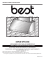
WPD39M SERIES
HB0113
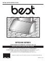
INSTALLATION INSTRUCTIONS
INTENDED FOR DOMESTIC COOKING ONLY
INSTALLER: LEAVE THIS MANUAL WITH HOMEOWNER.
HOMEOWNER: USE AND CARE INFORMATION ON PAGES 9 AND 10.
READ AND SAVE THESE INSTRUCTIONS
SV20611 rev. 05
! !
BEST; Hartford, Wisconsin www.BestRangeHoods.com 800 558-1711
BEST; Drummondville, QC, Canada www.BestRangeHoods.com 866 737-7770
To register your product online or for additional information visit www.BestRangeHoods.com

2
TO REDUCE THE RISK OF FIRE, ELECTRIC SHOCK OR
INJURY TO PERSONS, OBSERVE THE FOLLOWING:
1. Use this unit only in the manner intended by the manufacturer.
If you have questions, contact the manufacturer at the address
or telephone number listed in the warranty.
2. Before servicing or cleaning unit, switch power off at service
panel and lock service disconnecting means to prevent
power from being switched on accidentally. When the service
disconnecting means cannot be locked, securely fasten a
prominent warning device, such as a tag, to the service panel.
3. Installation work and electrical wiring must be done by
qualified personnel in accordance with all applicable codes
and standards, including fire-rated construction codes and
standards.
4. Sufficient air is needed for proper combustion and exhausting
of gases through the flue (chimney) of fuel burning equipment
to prevent backdrafting. Follow the heating equipment
manufacturer’s guidelines and safety standards such as
those published by the National Fire Protection Association
(NFPA) and the American Society for Heating, Refrigeration
and Air Conditioning Engineers (ASHRAE) and the local code
authorities.
5. When cutting or drilling into wall or ceiling, do not damage
electrical wiring and other hidden utilities.
6. Ducted fans must always be vented to the outdoors.
7. Do not use this unit with any additional solid-state speed
control device.
8. To reduce the risk of fire, use only metal ductwork.
9. This unit must be grounded and protected by a GFCI.
10. Suitable for use in damp locations only when installed in a
GFCI PROTECTED branch-circuit.
11. This unit is not designed to be used with a charcoal grill.
12. When applicable local regulations comprise more
restrictive installation and/or certification requirements,
the aforementioned requirements prevail on those of this
document and the installer agrees to conform to these at his
own expense.
TO REDUCE THE RISK OF A RANGE TOP GREASE FIRE:
a) Never leave surface units unattended at high settings. Boilovers
cause smoking and greasy spillovers that may ignite. Heat oils
slowly on low or medium settings.
b) Always turn hood ON when cooking at high heat or when
flambeing food (i.e.: Crêpes Suzette, Cherries Jubilee,
Peppercorn Beef Flambé).
c) Clean ventilating fans frequently. Grease should not be allowed
to accumulate on fan, filters or in exhaust ducts.
d) Use proper pan size. Always use cookware appropriate for the
size of the surface element.
1. For general ventilating use only. Do not use to exhaust
hazardous or explosive materials and vapors.
2. To avoid motor bearing damage and noisy and/or unbalanced
impellers, keep drywall spray, construction dust, etc. off power
unit.
3. Your hood motor has a thermal overload which will
automatically shut off the motor if it becomes overheated. The
motor will restart when it cools down. If the motor continues to
shut off and restart, have the hood serviced.
4. For best capture of cooking impurities, the bottom of the hood
must be located at a distance of 36" above cooking surface.
5. Two installers are recommended because of the large size and
weight of this unit.
6. To reduce the risk of fire and to properly exhaust air, be sure to
duct air outside — Do not exhaust air into spaces within walls
or ceiling or into attics, crawl space or garage.
7. This product is equipped with a thermostat which may start
blower automatically. To reduce the risk of injury and to prevent
power from being switched on accidentally, switch power off at
service panel and lock or tag service panel.
8. To reduce the risk of fire and electrical shock, the Best WPD39M
Series hood must be installed with Best interior blower model
P12; Best exterior blower models EB12 or EB15; Best in-line
blower model ILB11. Other blowers cannot be substituted.
(Blowers sold separately.)
9. Please read specification label on product for further
information and requirements.
WARNING
!
CAUTION
TO REDUCE THE RISK OF INJURY TO PERSONS IN THE
EVENT OF A RANGE TOP GREASE FIRE, OBSERVE
THE FOLLOWING*:
1. SMOTHER FLAMES with a close-fitting lid, cookie sheet or
metal tray, then turn off the burner. BE CAREFUL TO PREVENT
BURNS. IF THE FLAMES DO NOT GO OUT IMMEDIATELY,
EVACUATE AND CALL THE FIRE DEPARTMENT.
2. NEVER PICK UP A FLAMING PAN — You may be burned.
3. DO NOT USE WATER, including wet dishcloths or towels —
This could cause a violent steam explosion.
4. Use an extinguisher ONLY if:
A. You own a Class ABC extinguisher and you know how to
operate it.
B. The fire is small and contained in the area where it started.
C. The fire department has been called.
D. You can fight the fire with your back to an exit.
* Based on “Kitchen Fire Safety Tips” published by NFPA.
WARNING
!

3
HL0188
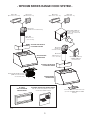
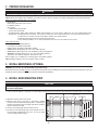
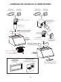
- WPD39M SERIES RANGE HOOD SYSTEM -
MODEL 441
(10" ROUND WALL CAP)
M
ODEL ILB11 (1100 CFM)
IN-LINE BLOWER (INCLUDES
TWO 8" X 12" TO 10" ROUND
TRANSITIONS)
M
ODEL EB12 (1200 CFM)
OR EB15 (1500 CFM)
EXTERIOR BLOWER
MODEL 437
(HIGH CAPACITY ROOF CAP)
I
N-LINE AND EXTERIOR BLOWER ROUGH-IN KIT
(INCLUDED WITH EB12, EB15 AND ILB11
BLOWERS.)
OPTIONAL
WALL EXTENSION
AWWPD SERIES
MODEL P12 BLOWER/ROUGH-IN KIT
(1200 CFM INTERIOR BLOWER
AND ROUGH-IN PLATE)
MODEL 418
(10" ROUND ADJUSTABLE ELBOW)
M
ODEL 441
(10" ROUND WALL CAP)
MODEL 437
(HIGH CAPACITY ROOF CAP)
M
ODEL 410
(10" ROUND DUCT
— 2 FT. SECTIONS)
OPTIONAL DECORATIVE
FLUE AEWPD SERIES
WPD39M SERIES
RANGE HOOD
WPD39M SERIES
RANGE HOOD
OPTIONAL DECORATIVE
FLUE AEWPD SERIES
OPTIONAL BACKSPLASH ABWPD SERIES
36", 42"
OR 48" WIDTH (STAINLESS STEEL WALL
COVERING WITH WARMING SHELVES)
MODEL 410
(10" ROUND DUCT
— 2 FT. SECTIONS)
MODEL 418
(10" ROUND
ADJUSTABLE ELBOW)

4
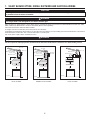
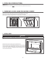
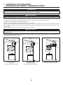
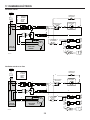
Either an interior or exterior blower or in-line blower may be used with this range hood. It must be installed with blower models P12, ILB11,
EB12 or EB15 only. Other blowers cannot be substituted. (Blowers sold separately).
Plan where and how the ductwork will be installed.
A straight, short duct run will allow the hood to perform most efficiently.
Install proper-sized ductwork, elbows and roof or wall cap for the type of blower you are installing. Connect metal ductwork to cap and work
back towards the hood location. Use 2" metal foil duct tape to seal the joints.
Run 3-wire power supply cable to installation location.
For best capture of cooking impurities, the bottom of the hood must be located at a distance of 36" above cooking surface.
M
ODEL P12 DUAL INTERIOR BLOWER
TYPICAL DUCTWORK
1. SELECT BLOWER OPTION, INSTALL DUCTWORK AND ELECTRICAL WIRING
18"
WALL CAP
36" MINIMUM ABOVE
COOKING
SURFACE
16" TO
TOP
OF WOOD
MOUNTING
STRIP
OPTIONAL DECORATIVE
FLUE
OR SOFFIT
HH0185A
ROOF CAP
10" ROUND DUCT
10" ROUND ELBOW
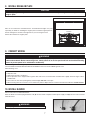
MODEL EB12 OR EB15 EXTERIOR
B
LOWER TYPICAL DUCTWORK
EXTERIOR
BLOWER
EXTERIOR
BLOWER
18"
36" MINIMUM ABOVE
COOKING
SURFACE
16" TO
TOP
OF WOOD
MOUNTING
STRIP
OPTIONAL DECORATIVE
FLUE
OR SOFFIT
HH0183A
10" ROUND DUCT
10" ROUND ELBOW
MODEL ILB11 IN-LINE BLOWER
TYPICAL DUCTWORK
IN-LINE BLOWER
10" ROUND DUCT
HH0184A
36" MINIMUM ABOVE
COOKING
SURFACE
ROOF CAP
WALL
CAP
CAUTION
This range hood is intended for outdoor covered patio or lanai area. As with all electric appliances, this unit must
be protected from the effects of weather.
WARNING
!
This range hood is not designed for use with a charcoal grill.
WARNING
!
The power cable must be a GFCI protected branch circuit.

5
3. INSTALL BACKSPLASH (OPTIONAL)
ABWPD Series (for 36", 42" and 48" widths range hoods only)
Backsplash must be installed before the hood shell and wall extension (if needed) because the hood shell (and wall extension) covers the
backsplash top mounting screws (see instructions packed with backsplash).
WARNING
!
When performing installation, servicing or cleaning the unit, it is recommended to wear safety glasses and gloves.
NOTE: Before proceeding to the installation, check the contents of the box. If items are missing or damaged, contact the manufacturer.
Make sure that the following items are included:
- Range hood
- Wood strip (attached to back of hood)
- Installation manual
- Accessories:
• 4 Baffle filters with handles
• Grease tray with handle
• Shielded halogen bulbs (120 V, 50 W max., MR16 with GU10 base) (2 for 36" and 42" width hoods, 3 for 48" and 60" width hoods)
• Bag of parts: 3 waterproof wire connectors, 2 no. 8 x 5/8" screws, 6 no. 10 x 2" hex head screws, 4 no. 10 x 2" flat head screws,
2 wall anchors, 6 washers 3/16" ID x 3/4" OD, 4 stainless steel 10-32 locknuts
Included in parts bag, but not to be used (please discard):
2 wire clamps LP16-AP, 2 no. 8 x 3/8" zinc-plated screws, 8 no. 8 x 3/8" stainless steel screws
Parts sold separately:
- Interior blower assembly model P12
- In-line blower assembly model ILB11
- Exterior blower assembly model EB12 or EB15
- ABWPD Series Backsplash, 36", 42" or 48" width (optional)
- AEWPD Series Decorative flue, to be installed over the hood (optional)
- AWWPD Series Wall extension, 36", 42", 48" or 60" width (optional)
- Transitions, duct, elbows, dampers, wall and roof caps
Refer to page 4 for a complete list of venting options and model numbers.
NOTE: During installation, protect countertop and/or cooktop.
2. PREPARE INSTALLATION
4. INSTALL WOOD MOUNTING STRIP
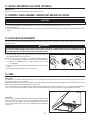
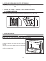
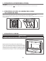
1. Proper structural support is required to accommodate the weight of the hood. Construct the wall framing using minimum 2" x 4" lumbers.
2. Mark the center location of the hood.
3. Measure and mark a level line on wall above cooktop
location for the wood mounting strip. Install 2" x 4" blockings
between wall studs where mounting strip will be installed.
Refer to illustration at right.
4. Remove wood mounting strip from back of hood.
5. Position the wood mounting strip on the wall and secure to
the wall studs and blockings using 4 no. 10 x 2" flat head
screws (included in parts bag).
CAUTION
Due to the weight of this hood, ensure that the wood strip is attached to all of the available wall studs and blocking;
not into the wall alone.
HD0482A
Existing
Wall Studs
2" x 4"
Blocking
Back of Hood
Wood Mounting
Strip
14¼"
15
1
⁄8"
16"
18"

6
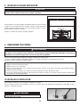
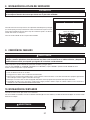
7. INSTALL HOOD
WARNING
!
Hold the hood until it is completely secured to the wood mounting strip.
Rest the back cavity of the hood on the wood mounting strip.
Secure the hood to the wood mounting strip using 5 no. 10 x 2" hex head
screws at locations shown at right. Drill two 3/16" diameter holes into the wall
for wall anchors through the existing holes in the lower back of the hood at
locations shown at right. Then, install both wall anchors with both no. 8 x 5/8"
screws and washers provided.
HD0479
W
ALL
ANCHORS
LOCATION
M
OUNTING
SCREWS
LOCATION
5. INSTALL WALL EXTENSION (OPTIONAL)
AWWPD Series
Wall extension must be installed before the hood (see instructions packed with wall extension).
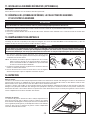
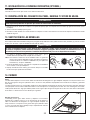
6. REMOVE BAFFLE FILTERS, GREASE TRAY AND PANEL ASSEMBLY
Remove tape on filters. Remove filters from hood (as illustrated below) and set aside.
Remove tape on grease tray. Lift and pull grease tray to remove and set aside.
Remove panel assembly retaining screws (4, 5 or 6 depending on hood width) and set aside. Tilt panel assembly forward.
HD0461
1
2
GREASE TRAY
R
ETAINING
SCREW
LOCATIONS

7
8. INSTALL ROUGH-IN PLATE
Refer to the instructions included with the selected blower/rough-in kit (sold
separately) for details on installing the rough-in plate. Install the rough-in plate so
that the wiring box is located on the right side as you are facing the hood.
Attach 10" round duct to rough-in plate.
CAUTION
Install rough-in plate using 4 x 10-32 locknuts and washers included in hood parts bag. Discard nuts provided with
rough-in plate.
HD0480
LOCKNUTS
9. CONNECT WIRING
Remove wiring cover from rough-in plate and set aside.
Connect BLACK to BLACK, WHITE to WHITE and GREEN or bare wire under GREEN ground screw.
Reinstall wiring cover.
WARNING
!
Risk of electric shock. Electrical wiring must be done by qualified personnel in accordance with all applicable
codes and standards. Before connecting wires, switch power off at service panel and lock service disconnecting
means to prevent power to be switched on accidentally.
WATERPROOF WIRE CONNECTORS INSTRUCTIONS:
1. Strip wires 3/8".
2. Align frayed strands or conductors.
3. Do not pre-twist. Place stripped wires together with ends even, but lead smaller stranded wires slightly ahead of larger solid or
stranded wire.
4. Twist connector onto wires pushing firmly until hand-tight. DO NOT over torque.
5. When inserting wires into connectors, some sealant may leak out. Wipe off excess sealant in and around conductors. DO NOT REUSE.
10. INSTALL BLOWER
Refer to instructions included with blower.
Once the blower is installed, plug the blower cord (A) into the female receptacle and the power supply cord (B) onto the male connector
inside the hood.
HE0078
AB
WARNING
!
Do not plug the two cords into each other.

8
11. INSTALL DECORATIVE FLUE COVER (OPTIONAL)
AEWPD Series
Refer to the instructions included with the optional decorative flue.
12. REINSTALL PANEL ASSEMBLY, GREASE TRAY AND BAFFLE FILTERS
CAUTION
Remove protective plastic film covering filters before installing them.
1. Push panel assembly back inside hood and secure to the hood using previously removed screws (see step 5).
2. Reinstall grease tray.
3. Insert one side of the filter into the side channel of the hood. Raise the other side toward the center of the hood and insert in the grease
drip rail.
13. LIGHT BULBS REPLACEMENT
This hood requires 120 V, 50 W, MR16 with GU10 base, shielded halogen bulbs (included). (2 for 36" and 42" width hood, 3 for 48" and
60" width hoods.)
1. To remove bulbs, gently push upwards and turn counterclockwise to
disengage bulb leads from their grooves.
NOTE: To ease removal of the bulbs, use a rubber dishwashing glove or
use suction cup tool available from Best. Contact Best Customer
Service at 1-800-558-1711 to order suction cup tool, part
no. 99526707.
2. Install the new bulbs by placing the bulb leads into their grooves in the
socket.
3. Gently push upwards and turn clockwise until secure.
WARNING
!
Do not touch lamps during or soon after operation. Burns may occur. In order to prevent the risk of personal injury,
only install shielded halogen lamps. Also, never install a cool beam, a dichroic lamp, a lamp not suitable for use in
recessed luminaires or identified for use in enclosed fixtures.
12 3
HO0199
14. CARE
Baffle Filters
The baffle filters should be cleaned frequently. Use a warm detergent solution. Wash more often if your cooking style generates greater
grease like frying foods or wok cooking.
Remove baffle filters by pushing them towards the side of the hood and rotating filters downward. Baffle filters are dishwasher safe. Allow
filters to dry completely before reinstalling them in the hood.
Clean all-metal filters in the dishwasher using a non-phosphate detergent. Discoloration of the filter may occur if using phosphate detergent
or as a result of local water conditions—but this will not affect filter performance. This discoloration is not covered by the warranty.
Grease Tray
The grease tray should be emptied and cleaned frequently. Remove from
hood (as illustrated at right) and use a warm detergent solution. Wash
more often if your cooking style generates greater grease like frying foods
or wok cooking. Allow grease tray to dry completely before reinstalling it
in the hood.
1
2
HD0481

9
Avoid when choosing a detergent:
- Any cleaners that contain bleach will attack stainless steel.
- Any products containing: chloride, fluoride, iodide, bromide will deteriorate surfaces rapidly.
- Any combustible products used for cleaning such as acetone, alcohol, ether, benzol, etc., are highly explosive and should never be
used close to a range.
14. CARE (CONT'D)
Hood cleaning
Stainless steel cleaning:
Do:
• Regularly wash with clean cloth or rag soaked with warm water
and mild soap or liquid dish detergent.
• Always clean in the direction of original polish lines.
• Always rinse well with clear water (2 or 3 times) after cleaning.
Wipe dry completely.
• You may also use a specialized household stainless steel
cleaner.
Don’t:
• Use any steel or stainless steel wool or any other scrapers to
remove stubborn dirt.
• Use any harsh or abrasive cleansers.
• Allow dirt to accumulate.
• Let plaster dust or any other construction residues reach the
hood. During construction/renovation, cover the hood to make
sure no dust sticks to stainless steel surface.
Grease Drip Rail
The grease drip rail should be cleaned frequently. Wash with clean cloth soaked in warm detergent solution. Wash more often if your
cooking style generates greater grease like frying foods or wok cooking.
Blower Cleaning
Access the blower and use vacuum to clean. Do not immerse in water.
15. OPERATION
BLOWER
The blower is operated using two controls.
Use the on/off rocker switch (1) to start and stop the blower. When turned ON, the
switch turns red and the blower operates at the speed set by the speed control
knob (2).
Turn the speed control knob clockwise to increase blower speed – counterclockwise
to decrease speed.
COOKTOP LIGHTING (HALOGEN)
Use the on/off rocker switch (3) to turn the halogen lights ON or OFF.
HC0060
1
2
3
1) ON/OFF blower switch
2) Blower speed control knob
3) Halogen light switch
HEAT SENTRY™
This hood is equipped with a Heat Sentry™ thermostat. This thermostat is a device that will turn on the blower to high speed if it senses
excessive heat above the cooking surface.
1) If blower is OFF - it turns blower ON to high speed.
2) If blower is already ON it sets blower on high speed.
When the temperature level drops to normal, the blower will return to its original setting.
WARNING
!
The HEAT SENTRY can start the blower during a range top fire or other excessive heat situations even if the hood
is turned off. In this case, it is impossible to turn the blower OFF using control panel switch. To stop the blower, do
it from the main electrical panel.

10
16. WARRANTY
FIVE-YEAR LIMITED WARRANTY FOR BEST
®
PRODUCTS
Warranty Period and Exclusions: Broan-NuTone, LLC (the “Company”) warrants to the consumer purchaser of its product (“you”) that the product (the
“Product”) will be free from material defects in the materials or its workmanship for a period of five (5) years from the date of original purchase (or such
longer period as may be required by applicable law) or a period of two (2) years from the date of service for any labor provided on the Product.
The limited warranty period for any replacement parts provided by the Company and for any Products repaired or replaced under this limited warranty shall
be the remainder of the original warranty period (or such longer period as may be required by applicable law).
THIS WARRANTY DOES NOT EXTEND TO FLUORESCENT LAMP STARTERS, TUBES AND BULBS, FUSES, FILTERS, DUCTS, ROOF CAPS, WALL CAPS
AND OTHER ACCESSORIES FOR DUCTING. This warranty does not cover (a) normal maintenance and service, (b) normal wear and tear, (c) any Products or
parts which have been subject to misuse, abuse, abnormal usage, negligence, accident, improper or insufficient maintenance, storage or repair (other than
repair by the Company), (d) damage caused by faulty installation, or installation or use contrary to recommendations or instructions, (f) damage caused by
exposure to salt air, (g) damage in transit, (h) natural wear of finish, (i) Products in commercial or nonresidential use, (j) damage caused by fire, flood or
other act of God, or (k) Products with altered, defaced or removed serial numbers. This warranty covers only Products sold to consumers in North America.
This warranty supersedes all prior warranties and, subject to applicable law, is not transferable from the original consumer purchaser.
No Other Warranties: This Limited Warranty contains the Company’s sole obligation and your sole remedy for defective Products. The foregoing warranties
are exclusive and in lieu of any other warranties and conditions, express or implied. TO THE MAXIMUM EXTENT PERMITTED BY APPLICABLE LAW, THE
COMPANY DISCLAIMS AND EXCLUDES ALL OTHER EXPRESS WARRANTIES AND CONDITIONS, AND DISCLAIMS AND EXCLUDES ALL WARRANTIES
AND CONDITIONS IMPLIED BY LAW, INCLUDING WITHOUT LIMITATION THOSE OF MERCHANTABILITY AND FITNESS FOR A PARTICULAR PURPOSE.
To the extent that applicable law prohibits the exclusion of implied warranties or conditions, the duration of any applicable implied warranty or condition
is limited to the period specified for the express warranty above. Some jurisdictions (which may include the Province of Quebec or specific US states) do
not allow limitations on how long an implied warranty lasts, so the above limitation may not apply to you. Any oral or written description of the Product is
for the sole purpose of identifying it and shall not be construed as an express warranty.
Whenever possible, each provision of this Limited Warranty shall be interpreted in such manner as to be effective and valid under applicable law, but if any
provision is held to be prohibited or invalid, such provision shall be ineffective only to the extent of such prohibition or invalidity, without invalidating the
remainder of such provision or the other remaining provisions of the Limited Warranty.
Remedy: During the applicable limited warranty period, the Company will, at its option, provide replacement parts for, or repair or replace, without charge,
any Product or part thereof, to the extent the Company finds it to be covered by and in breach of this limited warranty under normal use and service. The
Company will ship the repaired or replaced Product or replacement parts to you at no charge. You are responsible for all costs for removal, reinstallation
and shipping, insurance or other freight charges incurred in the shipment of the Product or part to the Company. If you must send the Product or part
to the Company, as instructed by the Company, you must properly pack the Product or part—the Company is not responsible for damage in transit. The
Company reserves the right to utilize reconditioned, refurbished, repaired or remanufactured Products or parts in the warranty repair or replacement
process. Such Products and parts will be comparable in function and performance to an original Product or part and warranted for the remainder of the
original warranty period (or such longer period as may be required by applicable law).
Company reserves the right, in its sole discretion, to refund the money actually paid by you for the Product. If the Product or component is no longer
available, replacement may be made with a similar product of equal or greater value, at Company’s sole discretion. This is your sole and exclusive remedy
for breach of this limited warranty.
Exclusion of Damages: THE COMPANY’S OBLIGATION TO PROVIDE REPLACEMENT PARTS, OR REPAIR OR REPLACE, AT THE COMPANY’S OPTION,
SHALL BE YOUR SOLE AND EXCLUSIVE REMEDY UNDER THIS LIMITED WARRANTY AND THE COMPANY’S SOLE AND EXCLUSIVE OBLIGATION. THE
COMPANY SHALL NOT BE LIABLE FOR INCIDENTAL, INDIRECT, CONSEQUENTIAL OR SPECIAL DAMAGES ARISING OUT OF OR IN CONNECTION WITH
THE PRODUCT, ITS USE OR PERFORMANCE.
Some jurisdictions do not allow the exclusion or limitation of incidental or consequential damages, so the above limitation or exclusion may not apply
to you. This warranty gives you specific legal rights, and you may also have other rights, which vary from jurisdiction to jurisdiction. The disclaimers,
exclusions, and limitations of liability under this warranty will not apply to the extent prohibited by applicable law.
This warranty covers only replacement or repair of defective Products or parts thereof at the Company’s main facility and does not include the cost of field
service travel and living expenses.
Any assistance the Company provides to or procures for you outside the terms, limitations or exclusions of this limited warranty will not constitute a waiver
of such terms, limitations or exclusions, nor will such assistance extend or revive the warranty. The Company will not reimburse you for any expenses
incurred by you in repairing or replacing any defective Product, except for those incurred with the Company’s prior written permission.
How to Obtain Warranty Service: To qualify for warranty service, you must (a) notify the Company at the address or telephone number stated below within
seven (7) days of discovering the covered defect, (b) give the model number and part identification and (c) describe the nature of any defect in the Product
or part. At the time of requesting warranty service, you must present evidence of the original purchase date. If you cannot provide a copy of the original
written limited warranty, then the terms of the Company’s most current written limited warranty for your particular product will control.
PRODUCT SPECIFICATIONS
All illustrations and specifications in this catalog are based on the latest product information available at time of production. Broan-NuTone, LLC and
BEST® reserves the right to make changes at any time, without notice, in prices, colors, materials, equipment, specifications and models, place of
manufacture and to discontinue models or equipment.
Best
Broan-NuTone, LLC- 926 W. State Street, Hartford, WI 53207 1-800-637-1453
Best®, 550 Lemire Blvd., Drummondville, QC, Canada (1-866-737-7770) www.bestrangehoods.com

11
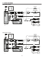
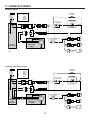
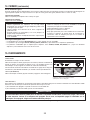
17. WIRING DIAGRAMS
Internal blower assembly
LINE
NEUTRAL
GROUND
120 VAC
WHT
GRN
BLK
ROUGH-IN
PLATE
WHT
WHT
WHT
WHT
BLK
BLK
BLK
RED
BLK
YEL
LAMPLAMP
HEAT SENTRY
THERMOSTAT
SPEED CONTROL
LAMP
SWITCH
FAN SWITCH
COLOR CODE
BLK BLACK
GRN GREEN
RED RED
WHT WHITE
YEL YELLOW
INTERNAL
BLOWER ASSEMBLY
M
WHT
YEL
WHT
BLK
BLK
RED
LAMP
WHT
WHT
YEL
YEL
HE0139A
Remote blower assembly
LINE
NEUTRAL
GROUND
120 VAC
WHT
WHT
WHT
BLK
BLK
YEL
BLK
RED
YEL
LAMPLAMPLAMP
HEAT SENTRY
THERMOSTAT
SPEED CONTROL
LAMP
SWITCH
FAN SWITCH
COLOR CODE
BLK BLACK
GRN GREEN
RED RED
WHT WHITE
YEL YELLOW
ROUGH-IN
PLATE
REMOTE
BLOWER ASSEMBLY
HE0140A
M
WHT
BLK
BLK
WHT
GRN
WHT
GRN
BLK
WHT
WHT
BLK
BLK
WHT
WHT
YEL
YEL
RED

12
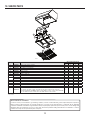
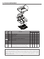
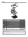
18. SERVICE PARTS
HL0190
1
2
3
4
5
6
7
8
9
10
REPLACEMENT PARTS AND REPAIRS
In order to ensure your unit remains in good working condition, you must use Broan-NuTone genuine replacement parts only. Broan-
NuTone genuine replacement parts are specially designed for each unit and are manufactured to comply with all the applicable
certification standards and maintain a high standard of safety. Any third party replacement part used may cause serious damage and
drastically reduce the performance level of your unit, which will result in premature failing. Broan-NuTone recommends to contact a
certified service depot for all replacement parts and repairs.
KEY NO.PART NO.DESCRIPTION
QTY. (RANGE HOOD WIDTH)
36" 42" 48" 60"
1 SV60887 LIGHT SOCKET HOLDER ASSEMBLY 2233
2 SV05921 SHIELDED HALOGEN BULB (120 V, 50 W, GU10 BASE) 2233
3 SV03435 H
EAT SENTRY™ THERMOSTAT 1111
4 SV08549 FAN KNOB 1111
5 SV03501 SPEED CONTROL 1111
6 SV13924 MALE CONNECTOR 1111
7 SV13923 FEMALE CONNECTOR 1111
8 SV60879 GREASE TRAY 1111
9
SV60675 BAFFLE FILTER 11.84" X 15.125" (HANDLE INCLUDED) 2222
SV60716 BAFFLE FILTER 8.84" X 15.125" (HANDLE INCLUDED) 2222
10 SV08337 FILTER SPRING 4444
* SV02563 L
IGHT ROCKER SWITCH 1111
* SV03503 BLOWER ROCKER SWITCH 1111
* SV05869 BEST LOGO 1111
* SV20611 INSTALLATION GUIDE 1111
* SV04216
PARTS BAG: 3 WATERPROOF WIRE CONNECTORS, 2 NO. 8 X 5/8" SCREWS,
6 NO. 10 X 2" HEX HEAD SCREWS, 4 NO. 10 X 2" FLAT HEAD SCREWS, 2 WALL ANCHORS,
6 WASHERS 3/16" ID X 3/4" OD, 4 STAINLESS STEEL 10-32 LOCKNUTS, 2 WIRE CLAMPS LP16-AP,
2 NO. 8 X 3/8" ZINC-PLATED SCREWS, 8 NO. 8 X 3/8" STAINLESS STEEL SCREWS
1111
* NOT SHOWN.

CONÇUE POUR USAGE DOMESTIQUE SEULEMENT
INSTALLATEUR : LAISSER CE GUIDE AU PROPRIÉTAIRE.
PROPRIÉTAIRE : DIRECTIVES D’UTILISATION ET D’ENTRETIEN
EN PAGES 21 ET 22.
LIRE ET CONSERVER CES DIRECTIVES
! !
SÉRIE WPD39M
BEST; Hartford, Wisconsin www.BestRangeHoods.com 800 558-1711
BEST; Drummondville, QC, Canada www.BestRangeHoods.com 866 737-7770
Pour enregistrer votre produit en ligne ou pour obtenir plus d’information, consultez notre site www.BestRangeHoods.com
HB0113
GUIDE D’INSTALLATION
SV20611 rév. 05

14
AFIN DE RÉDUIRE LES RISQUES D’INCENDIE,
D’ÉLECTROCUTION OU DE BLESSURES CORPORELLES,
SUIVEZ LES DIRECTIVES SUIVANTES :
1. N’utilisez cet appareil que de la façon prévue par le
manufacturier. Si vous avez des questions, contactez le
manufacturier à l’adresse ou au numéro de téléphone indiqués
dans la garantie.
2. Avant de réparer ou de nettoyer l’appareil, couper l’alimentation
électrique en verrouillant le panneau de distribution afin
d’éviter sa remise en marche accidentelle. Si le panneau de
distribution ne peut être verrouillé, y fixer un avertissement en
évidence, telle qu’une étiquette de couleur vive.
3. Les travaux d’installation et de raccordement électrique doivent
être effectués par une personne qualifiée, conformément
aux codes et aux standards de construction, incluant ceux
concernant la protection contre les incendies.
4. Une quantité d’air adéquate est requise afin d’assurer une
bonne combustion et l’évacuation des gaz par la cheminée
dans le cas des équipements alimentés au gaz afin de prévenir
les retours de cheminée. Conformez-vous aux instructions et
aux standards de sécurité des manufacturiers d’équipement de
chauffage, tel qu’ils sont publiés par la National Fire Protection
Association (NFPA) et l’American Society for Heating,
Refrigeration and Air Conditioning Engineers (ASHRAE) ainsi
que les responsables des codes locaux.
5. Veillez à ne pas endommager le câblage électrique ou d’autres
équipements non apparents lors de la découpe ou du perçage
du mur ou du plafond.
6. Les ventilateurs avec conduits doivent toujours évacuer l’air
à l’extérieur.
7. Ne pas utiliser cet appareil avec une commande de vitesse à
semiconducteur additionnelle.
8. Afin de réduire les risques d’incendie, n’utilisez que des conduits
de métal.
9. Cet appareil doit être mis à la terre et protégé par un DDFT
(disjoncteur de fuite à la terre).
10. Convient à une utilisation dans des lieux humides seulement
lorsqu’elle est raccordée à un DISJONCTEUR DE FUITE À LA
TERRE (DDFT).
11. Cet appareil n’est pas conçu pour être utilisé avec un barbecue
au charbon de bois.
12. Lorsqu’une réglementation est en vigueur et qu’elle comporte
des exigences d’installation et/ou de certification plus
restrictives, lesdites exigences prévalent sur celles de ce
document et l’installateur entend s’y conformer à ses frais.
AFIN DE RÉDUIRE LES RISQUES DE FEU
DE CUISINIÈRE :
a) Ne jamais laisser les appareils de cuisson sans surveillance
lorsqu’ils sont réglés à feu vif. Les débordements engendrent
de la fumée et des déversements graisseux pouvant
s’enflammer. Chauffez l’huile lentement, à feu doux ou moyen.
b) Mettez toujours la hotte en marche lorsque vous cuisinez à feu
vif ou que vous cuisinez des mets flambés (par ex. : crêpes
Suzette, cerises jubilé, steaks au poivre flambés).
c) Nettoyez régulièrement la (les) roue(s) du ventilateur. Ne
laissez pas la graisse s’accumuler sur le ventilateur, les filtres
ou les conduits d’évacuation.
d) Utilisez le bon format de casserole. Servez-vous toujours de
casseroles et d’ustensiles appropriés à la dimension de la
surface chauffante.
1. Pour usage domestique seulement. Ne pas utiliser pour
évacuer des vapeurs ou des matières dangereuses
ou explosives.
2. Afin d’éviter tout dommage au moteur et de débalancer ou de
rendre bruyante la roue du moteur, garder votre appareil à l’abri
des poussières de gypse et de construction/rénovation, etc.
3. Le moteur de votre hotte possède une protection thermique
qui éteindra automatiquement le moteur s’il devient surchauffé.
Le moteur redémarrera automatiquement une fois refroidi. Si
le moteur continue à arrêter et à redémarrer, faites-le vérifier.
4. Pour une meilleure évacuation des odeurs de cuisson, le
bas de votre hotte doit être situé à une distance de 36 po
au-dessus de la surface de cuisson.
5. Deux installateurs sont recommandés lors de l’installation vu
la grande dimension et le poids de cet appareil.
6. Afin de réduire les risques d’incendie, assurez-vous d’évacuer
l’air à l’extérieur. Ne pas évacuer l’air dans des espaces
restreints comme l’intérieur des murs ou plafond ou dans le
grenier, faux plafond ou garage.
7. Cet appareil est équipé d’un thermostat pouvant faire démarrer
le ventilateur automatiquement. Afin de réduire le risque de
blessure, couper le courant à partir du panneau électrique
et le verrouiller ou apposer un avertissement sur le panneau afin
de prévenir que la hotte ne soit mise en marche accidentellement.
8. Afin de réduire les risques d’incendie et d’électrocution, la
hotte Best de série WPD39M doit être installée uniquement
avec le ventilateur intérieur Best P12, ou un des ventilateurs
extérieurs Best suivants : EB12 ou EB15, ou le ventilateur en
ligne Best ILB11 (vendus séparément). Aucun autre ventilateur
ne doit être utilisé.
9. Veuillez consulter l’autocollant apposé à l’intérieur du produit
pour plus d’information ou autres exigences.
AVERTISSEMENT
!
ATTENTION
AVERTISSEMENT
!
AFIN D’ÉVITER TOUT RISQUE DE BLESSURES LORS D’UN
FEU DE CUISINIÈRE, SUIVEZ CES DIRECTIVES* :
1. Étouffez les flammes avec un couvercle hermétique, une tôle à
biscuits ou un plateau métallique et ensuite, éteindre le brûleur.
PRENEZ SOIN D’ÉVITER les brûlures. SI LES FLAMMES
NE S’ÉTEIGNENT PAS IMMÉDIATEMENT, ÉVACUEZ LES
LIEUX ET APPELEZ LES POMPIERS.
2. NE PRENEZ JAMAIS UNE CASSEROLE EN FLAMMES
DANS VOS MAINS. Vous pourriez vous brûler.
3. N’UTILISEZ PAS D’EAU, incluant un linge à vaisselle ou une
serviette mouillée, cela pourrait occasionner une violente
explosion de vapeur.
4. N’utilisez un extincteur QUE DANS LE CAS OÙ :
A. Vous savez qu’il s’agit d’un extincteur de classe ABC et
que vous en connaissez le fonctionnement.
B. Le feu est petit et limité à l’endroit où il a débuté.
C. Les pompiers ont été avisés.
D. Vous pouvez combattre l’incendie en ayant accès à une sor tie
de secours.
*Tirées du Kitchen Fire Safety Tips publié par la NFPA.

15
HL0188
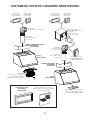
- SYSTÈME DE HOTTE DE CUISINIÈRE SÉRIE WPD39M -
MODÈLE 441
(C
APUCHON MURAL
10 PO ROND)
V
ENTILATEUR EN LIGNE
MODÈLE
ILB11 (1100 PI/MIN)
(INCLUANT DEUX
TRANSITIONS RONDES
DE 8 PO X 12 PO À 10 PO)
VENTILATEUR EXTÉRIEUR
MODÈLE
EB12 (1200 PI/MIN)
OU EB15 (1500 PI/MIN)
M
ODÈLE 437
(C
APUCHON DE TOIT
À HAUT RENDEMENT)
P
LAQUE VENTILATEUR POUR VENTILATEURS
EXTÉRIEURS OU EN LIGNE (INCLUSE AVEC
LES MODÈLES EB12, EB15 ET ILB11)
RALLONGE DE HOTTE
OPTIONNELLE
SÉRIE AWWPD
MODÈLE P12
VENTILATEUR/PLAQUE VENTILATEUR
(VENTILATEUR INTÉRIEUR DE
1200 PI/MIN ET PLAQUE VENTILATEUR)
MODÈLE 418
(COUDE AJUSTABLE DE 10 PO ROND)
M
ODÈLE 410
(CONDUIT 10 PO ROND,
SECTIONS 2 PI)
CHEMINÉE DÉCORATIVE
OPTIONNELLE
SÉRIE AEWPD
HOTTE
SÉRIE WPD39M
HOTTE
SÉRIE WPD39M
CHEMINÉE DÉCORATIVE
OPTIONNELLE
SÉRIE AEWPD
DOSSERET OPTIONNEL SÉRIE ABWPD
L
ARGEUR DE 36 PO, 42 PO OU 48 PO
(RECOUVREMENT DE MUR EN ACIER INOXYDABLE
AVEC SUPPORT ASSIETTES)
MODÈLE 410
(CONDUIT 10 PO ROND,
SECTIONS 2 PI)
MODÈLE 418
(COUDE AJUSTABLE
DE 10 PO ROND)
M
ODÈLE 441
(C
APUCHON MURAL
10 PO ROND)
M
ODÈLE 437
(C
APUCHON DE TOIT
À HAUT RENDEMENT)

16
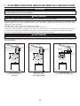
Cette hotte fonctionne autant avec un ventilateur intérieur, en ligne ou extérieur. La hotte de modèle Best de série WPD39M doit être
installée uniquement avec l’un des ventilateurs suivants : P12, ILB11, EB12 ou EB15. Aucun autre ventilateur ne peut être utilisé.
(Ventilateurs vendus séparément).
Déterminer à quel endroit et comment les conduits seront installés.
Un conduit droit et court permettra à votre hotte de fonctionner plus efficacement.
Installer des conduits de dimensions adéquates, des coudes et un capuchon de toit ou de mur. Relier le conduit de métal au capuchon,
puis acheminer le conduit jusqu’à l’emplacement de votre hotte. Sceller les joints avec du ruban adhésif de métal de 2 po de largeur.
Acheminer un câble d’alimentation électrique à 3 conducteurs jusqu’à l’emplacement de la hotte.
Pour une meilleure évacuation des odeurs de cuisson, le bas de la hotte doit être situé à une distance de 36 po au-dessus de la
surface de cuisson.
I
NSTALLATION TYPIQUE
V
ENTILATEUR INTÉRIEUR DOUBLE
MODÈLE P12
1. SÉLECTIONNER LE VENTILATEUR, INSTALLER LES CONDUITS ET LE CÂBLAGE ÉLECTRIQUE
18 PO
CAPUCHON
MURAL
MINIMUM DE 36 PO
AU-DESSUS DE LA
SURFACE DE CUISSON
DISTANCE DE
16 PO JUSQU’AU
DESSUS
DE LA
LISIÈRE
DE BOIS
CHEMINÉE DÉCORATIVE
OPTIONNELLE
OU SOFFITE
HH0185F
CAPUCHON DE TOIT
CONDUIT ROND DE 10 PO
COUDE ROND DE 10 PO
INSTALLATION TYPIQUE
VENTILATEUR EXTÉRIEUR
MODÈLE EB12 OU EB15
VENTILATEUR
EXTÉRIEUR
VENTILATEUR
EXTÉRIEUR
HH0183F
18 PO
MINIMUM DE 36 PO
AU-DESSUS DE LA
SURFACE DE CUISSON
DISTANCE DE
16 PO JUSQU’AU
DESSUS
DE LA
LISIÈRE
DE BOIS
CHEMINÉE DÉCORATIVE
OPTIONNELLE
OU SOFFITE
CONDUIT ROND DE 10 PO
COUDE ROND DE 10 PO
INSTALLATION TYPIQUE
V
ENTILATEUR EN LIGNE MODÈLE ILB11
VENTILATEUR
EN LIGNE
HH0184F
CAPUCHON
DE
TOIT
CAPUCHON
MURAL
MINIMUM DE 36 PO
AU-DESSUS DE LA
SURFACE DE CUISSON
CONDUIT ROND DE 10 PO
ATTENTION
Cette hotte est conçue pour être utilisée sur un patio couvert ou une véranda. Comme tous les électroménagers,
cet appareil doit être à l’abri des intempéries.
AVERTISSEMENT
!
Cette hotte n’est pas conçue pour être utilisée avec un barbecue au charbon de bois.
AVERTISSEMENT
!
Le fil d’alimentation électrique doit être raccordé à un disjoncteur de fuite à la terre (DDFT).

17
AVERTISSEMENT
!
Il est recommandé de porter des lunettes et des gants de sécurité lors de l’installation, de l’entretien et de la
réparation de cet appareil.
3. INSTALLER LE DOSSERET (OPTIONNEL)
Série ABWPD (seulement pour les modèles de 36 po, 42 po et 48 po de largeur)
Le dosseret doit être installé avant la hotte, avant la rallonge de hotte (si installée) puisque celles-ci couvrent les vis d’installation du
dosseret (voir les directives fournies avec le dosseret).
2. PRÉPARER L’INSTALLATION
NOTE : Avant de commencer l'installation, vérifier le contenu de la boîte. Si des pièces sont manquantes ou endommagées, contacter
le manufacturier.
S’assurer que les articles suivants soient inclus :
- Hotte
- Lisière de bois (vissée à l’arrière de la hotte)
- Guide d’installation
- Accessoires :
• 4 filtres à chicane avec poignées
• Collecteur de graisses avec poignée
• Ampoules halogènes avec écran (120 V, 50 W max., MR16 à culot GU10) (2 pour les modèles de 36 po et de 42 po de largeur,
3 pour les modèles de 48 po et 60 po de largeur)
• Sac de pièces : 3 capuchons de connexion étanches, 2 vis n° 8 x 5/8 po, 6 vis à tête hexagonale n° 10 x 2 po, 4 vis à tête fraisée n° 10 x 2 po,
2 douilles à expansion, 6 rondelles de 3/16 po DI x 3/4 po DE, 4 contre-écrous 10-32 en acier inoxydable
Inclus dans le sac de pièces, mais à ne pas utiliser (svp jeter) :
2 serre-fils LP16-AP, 2 vis n° 8 x 3/8 po plaquées zinc, 8 vis en acier inoxydable n° 8 x 3/8 po
Pièces vendues séparément :
- Ventilateur intérieur/plaque ventilateur modèle P12
- Ventilateur en ligne/plaque ventilateur modèle ILB11
- Ventilateur extérieur/plaque ventilateur modèle EB12 ou EB15
- Dosseret de série ABWPD, 36 po, 42 po ou 48 po de largeur (optionnel)
- Cheminée décorative de série AEWPD, à être installée au-dessus de la hotte (optionnelle)
- Rallonge de hotte de série AWWPD, 36 po, 42 po, 48 po ou 60 po de largeur (optionnelle)
- Transitions, conduits, coudes, volets, capuchons de mur ou de toit
Consulter la page 16 pour la liste complète des accessoires de ventilation et les numéros de modèle.
NOTE : Lors de l’installation, protéger le plan de cuisson et le comptoir de cuisine.
4. INSTALLER LA LISIÈRE DE BOIS
1. Une structure de soutien appropriée est nécessaire afin de supporter adéquatement le poids de la hotte. Construire la charpente du
mur à l’aide de montants en 2 po x 4 po minimum.
2. Marquer l’emplacement du centre de la hotte.
3. Mesurer et tracer une ligne droite au-dessus de la surface
de cuisson pour l’emplacement de la lisière de bois. Installer
des entretoises en 2 po x 4 po entre les montants où la
lisière de bois sera installée. Voir l’illustration ci-contre.
4. Retirer la lisière de bois de l’arrière de la hotte.
5. Placer la lisière de bois au mur et la fixer aux montants et
aux entretoises à l’aide de 4 vis n° 10 x 2 po à tête fraisée
(incluses dans le sac de pièces).
ATTENTION
En raison du poids élevé de cette hotte, s’assurer que la lisière de bois soit bien rattachée à tous les montants et
entretoises disponibles; ne pas visser la lisière de bois seulement au mur.
HD0482F
Montants
actuels
Entretoise
en 2 po x 4 po
Dos de la hotte
Lisière
de bois
15
1
⁄8 po
16 po
18 po
14¼ po

18
7 INSTALLER LA HOTTE
AVERTISSEMENT
!
Retenir la hotte jusqu’à ce qu’elle soit complètement vissée à la lisière de bois.
En appuyant la hotte au mur, insérer la lisière de bois dans la cavité arrière
de la hotte.
Fixer la hotte à la lisière de bois à l’aide de 5 vis n° 10 x 2 po à tête hexagonale
aux endroit indiqués ci-contre. En se servant des trous existants dans la
hotte, percer le mur, aux endroits indiqués, de 2 trous de 3/16 po et y insérer
les douilles à expansion. Puis, fixer la hotte au mur avec les vis n° 8 x 5/8 po
restantes et les 2 rondelles fournies.
HD0479
E
MPLACEMENT
DES
DOUILLES
E
MPLACEMENT
DES
VIS
DE
RETENUE
5. INSTALLER LA RALLONGE DE HOTTE (OPTIONNELLE)
Série AWWPD
La rallonge de hotte doit être installée avant la hotte (voir les directives fournies avec la rallonge).
6. RETIRER LES FILTRES À CHICANE, LE COLLECTEUR DE GRAISSES
ET LE PANNEAU INFÉRIEUR
Retirer le ruban adhésif des filtres. Retirer les filtres de la hotte (tel qu’il est illustré ci-dessous) et les mettre de côté.
Retirer le ruban adhésif du collecteur de graisses. Soulever et tirer le collecteur afin de le retirer puis, le mettre de côté.
Retirer les vis de retenue du panneau inférieur (4, 5 ou 6 selon la largeur de la hotte) et les mettre de côté. Incliner le panneau vers l’avant.
HD0461
1
2
E
MPLACEMENT
DES
VIS

19
8. INSTALLER LA PLAQUE VENTILATEUR
Pour les détails concernant l’installation de la plaque ventilateur, voir les instructions
comprises avec l’ensemble ventilateur et plaque ventilateur (vendu séparément).
Installer la plaque ventilateur de façon à ce que son boîtier électrique se trouve à
droite lorsque vous faites face à la hotte.
Attacher le conduit rond de 10 po à la plaque ventilateur.
ATTENTION
Installer la plaque ventilateur à l’aide des 4 contre-écrous 10-32 et des rondelles inclus dans le sac de pièces de
la hotte. Jeter les écrous fournis avec la plaque ventilateur.
HD0480
CONTRE-ÉCROUS
9. BRANCHEMENT ÉLECTRIQUE
Retirer le couvercle du boîtier électrique de la plaque ventilateur et le mettre de côté.
Connecter le fil NOIR au NOIR, le fil BLANC au BLANC et le fil VERT ou dénudé à la vis VERTE de mise à la terre.
Remettre en place le couvercle du boîtier électrique.
AVERTISSEMENT
!
Risque d’électrocution. Le raccordement électrique doit être effectué par du personnel qualifié conformément
aux codes et aux standards. Avant d’effectuer le branchement, coupez l’alimentation électrique au panneau de
distribution et verrouillez-le pour éviter une mise en marche accidentelle.
DIRECTIVES POUR L’UTILISATION DES CAPUCHONS DE CONNEXION ÉTANCHES :
1. Dégainer les fils d’une longueur de 3/8 po.
2. Égaliser les brins ou les conducteurs.
3. Ne pas les tordre. Rapprocher les fils et mettre leurs bouts égaux, sauf pour les fils à brins plus petits, lesquels doivent dépasser
légèrement des fils plus gros.
4. Insérer les fils dans le capuchon de connexion en poussant légèrement et tordre. NE PAS trop tordre.
5. Un peu de scellant pourrait s’échapper lors de l’insertion des fils dans le capuchon de connexion. Essuyer l’excès de scellant autour
des conducteurs. NE PAS RÉUTILISER.
10. INSTALLER LE VENTILATEUR
Pour installer le ventilateur, voir les instructions comprises avec celui-ci.
Une fois installé, brancher le fil du ventilateur à la prise à 2 alvéoles (A) et le fil d’alimentation électrique de la hotte (B) à la fiche à
3 broches, à l’intérieur de la hotte.
HE0078
AB
AVERTISSEMENT
!
Ne jamais brancher ensemble le fil du ventilateur au fil
d’alimentation de la hotte.

20
11. INSTALLER LA CHEMINÉE DÉCORATIVE (OPTIONNELLE)
Série AEWPD
Voir les directives fournies avec la cheminée décorative optionnelle.
12. RÉINSTALLER LE PANNEAU INFÉRIEUR, LE COLLECTEUR DE GRAISSES
ET LES FILTRES À GRAISSES
ATTENTION
Avant d’installer les filtres à chicane, retirer la pellicule de plastique protectrice de ceux-ci.
1. Repousser le panneau inférieur dans la hotte et le fixer à la hotte à l’aide des vis précédemment retirée à l’étape 5.
2. Réinstaller le collecteur de graisses.
3. Insérer une extrémité du filtre dans le rail de côté de la hotte. Soulever l’autre extrémité vers le centre de la hotte et l’insérer dans
la gouttière.
13. REMPLACEMENT DES AMPOULES
L’éclairage de cette hotte est produit par des ampoules halogènes avec écran de 120 V, 50 W, MR16 à culot GU10 (incluses). (2 pour les
modèles de 36 po et de 42 po, 3 pour les modèles de 48 po et 60 po.)
1. Pour retirer les ampoules, pousser doucement vers le haut et tourner
dans le sens contraire des aiguilles d’une montre pour désengager les
conducteurs hors de leur rainure.
NOTE : Pour obtenir une meilleure prise de l’ampoule lors de son retrait,
utiliser un gant à vaisselle ou la ventouse de Best. Contacter le
Service à la clientèle de Best au 1 800 558-1711 pour commander
la ventouse, numéro de pièce 99526707.
2. Installer les nouvelles ampoules en glissant leurs conducteurs dans les
rainures, à l’intérieur des douilles.
3. Pousser doucement vers le haut et tourner dans le sens des aiguilles
d’une montre jusqu’à ce que les ampoules soient bien en place.
12 3
HO0199
14. ENTRETIEN
Filtres à chicane
Les filtres à chicane doivent être nettoyés fréquemment. Utiliser une solution d’eau chaude et de détergent. Les filtres à chicane doivent
être lavés plus souvent si vos habitudes de cuisson génèrent plus de graisse, par exemple de la friture ou des aliments sautés au wok.
Retirer les filtres en les poussant vers le côté de la hotte et en les retournant vers le bas.
Les filtres à chicane sont lavables au lave-vaisselle. Nettoyer les filtres fabriqués entièrement de métal au lave-vaisselle à l’aide d’un
détergent sans phosphate. L’utilisation d’un détergent avec phosphates ainsi que les conditions locales de l’eau peuvent entraîner une
décoloration des filtres, sans toutefois affecter leur performance. Cette décoloration n’est pas couverte par la garantie. Laisser les filtres
sécher complètement avant de les réinstaller dans la hotte.
Collecteur de graisses
Le collecteur de graisses devrait être vidé et nettoyé fréquemment. Le
retirer de la hotte (tel qu’il est illustré ci-contre) et utiliser une solution
d’eau chaude et de détergent. Le nettoyer plus souvent si vos habitudes de
cuisson génèrent plus de graisse, par exemple de la friture ou des aliments
sautés au wok. Laisser le collecteur de graisses sécher complètement
avant de le réinstaller dans la hotte.
1
2
HD0481
AVERTISSEMENT
!
Ne pas toucher aux lampes durant ou peu après leur utilisation. Peuvent causer des brûlures. Afin de réduire le risque
de blessures corporelles, n’installer que des ampoules halogènes avec écran. Aussi, ne jamais installer une ampoule à
faisceau froid, dichroïque, non conçue pour des luminaires encastrés ou conçue uniquement pour des luminaires fermés.
La page est en cours de chargement...
La page est en cours de chargement...
La page est en cours de chargement...
La page est en cours de chargement...
La page est en cours de chargement...
La page est en cours de chargement...
La page est en cours de chargement...
La page est en cours de chargement...
La page est en cours de chargement...
La page est en cours de chargement...
La page est en cours de chargement...
La page est en cours de chargement...
La page est en cours de chargement...
La page est en cours de chargement...
La page est en cours de chargement...
La page est en cours de chargement...
-
 1
1
-
 2
2
-
 3
3
-
 4
4
-
 5
5
-
 6
6
-
 7
7
-
 8
8
-
 9
9
-
 10
10
-
 11
11
-
 12
12
-
 13
13
-
 14
14
-
 15
15
-
 16
16
-
 17
17
-
 18
18
-
 19
19
-
 20
20
-
 21
21
-
 22
22
-
 23
23
-
 24
24
-
 25
25
-
 26
26
-
 27
27
-
 28
28
-
 29
29
-
 30
30
-
 31
31
-
 32
32
-
 33
33
-
 34
34
-
 35
35
-
 36
36


Best WPD39M42SB Guide d'installation
- Catégorie
- Hottes
- Taper
- Guide d'installation
- Ce manuel convient également à
dans d''autres langues
- English: Best WPD39M42SB Installation guide
- español: Best WPD39M42SB Guía de instalación
Documents connexes
-
Best WPD39M Serie Guide d'installation
-
-
-
Best WPD38I36SB Guide d'installation
-
-
-
-
-
-