EUROSYSTEMS 01 Mode d'emploi
- Catégorie
- Mini motoculteurs
- Taper
- Mode d'emploi

IT Istruzioni d'uso
EN Operating instructions
DE Bedienungsanweisung
FR Mode d'emploi
ES Instrucciones de uso
MOTOZAPPA ELETTRICA
ELECTRIC MOTORHOE
ELEKTRISCHE MOTORHACKE
MOTOBINEUSE ELECTRIQUE
MOTOAZADA ELECTRICA
Type: MZP02


12
A
B
C
D
E
F
2b
12
10
9
9
8
2
4
6
3
1
5
7
A
B

34
6
5
2
1

78
Marcia avanti
Forward drive
Fahrantrieb vorwärts
Marche avant
Marcha adelante
1
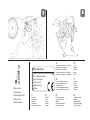
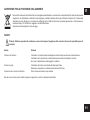
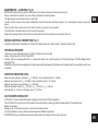
Costruttore
Manufacturer
Hersteller
Constructeur
Identicación fabricante
Manufacturer
Model: xxxxxxxxx | xxxxxxxxxxxx
Nr.: xxxxxxxxx-xxxxxx
Type: xxxxx xxxx
Date: aaaa / E
Weight: xxx kg
Power
1
2
3
4
5
6
7
8
2
Modello
Type
Modell
Modèle
Modelo
3
Numero di serie articolo – Progressivo
Serial number - Progressive
Serienummer Fortlaufend
Numéro de série article - Progressif
Número de serie artículo – Progresivo
4
Codice indenticativo prodotto
Product identication code
Produktkenncode
Code d’identication du produit
Código de identicación producto
5
Anno di costruzione
Year of construction
Baujahr
Année de construction
Año de construcción
6
Peso
Weight
Gewicht
Masse
Masa
7
Potenza
Power
Leistung
Puissance
Potencia
8
Tipologia prodotto
Category
Produktkategorie
Catégorie de produit
Tipología producto

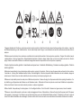
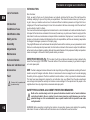
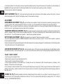
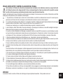
1 Leggere attentamente il libretto uso e istruzione prima di usare la macchina - Read the instructions manual before operating on the machine - Lesen Sie
die Gebrauchsanweisung vor der Inbetriebnahme - Lire le mode d'emploi avant l'usage - Leer atentamente el manual de instrucciones antes de utilizar la
máquina.
2 Attenzione pericolo rotazione fresa, mantenere una distanza di sicurezza dalla macchina in funzione (escluso operatore) - Danger: tiller rotation, keep at
a safety distance - Achtung: frasenrotation, Sicherheitsabstand einhalten - Attention: danger rotation fraise, se tenir à une distance de sécurité - Atención
peligro: fresas en movimiento. Mantener una distancia de seguridad cuando la máquina esté en función (excluso el operador).
3 Livello di potenza acustica garantita - Guaranteed sound power level - Garantierte Schallleistung - Puissance acoustique garantie - Potência
acústica garantida.
4 Attenzione tenere distante il cavo alimentazione della macchina, pericolo di tranciatura - Warning: keep the power cable well away from the machine.
It could be cut - Achtung: Das Gerätekabel entfernt halten, Durchschnittgefahr - Attention: disposer le câble d’alimentation loin de la machine, danger de
sectionnement - Atención: tener el cable de distribución de corriente lejo de la máquina, peligro de corte.
5 Rimuovere la spina dalla presa di corrente prima di effettuare le riparazioni - Remove the plug from the power socket before repairing the machine - Vor
der Ausführung von Reparaturen den Stecker aus der Steckdose ziehen - Débrancher la che de la prise de courant avant d’effectuer les réparations -
Quitar el enchufe de la toma de corriente antes de proceder a cualquier arreglamento.
6 Teme l'umidità - Keep well away from damp places - Vor Feuchtigkeit schützen - Craint l’humidité - Almacenar en lugares secos, teme la humedad.
7 Rimuovere la spina dalla presa di corrente se si notano danneggiamenti al cavo d'alimentazione - Remove the plug from the power socket if the power
cable appears to be damaged - Den Stecker aus der Steckdose ziehen, wenn das Gerätekabel Schäden aufweist - Débrancher la che de la prise de
courant si le câble d’alimentation est endommagé - Quitar el enchufe de la toma de corriente en caso de deterioro del cable de distribución de corriente.
7
1 2 3 4 5 6

Indice
Introduzione
Dati per l’identicazione
Condizioni di utilizzazioni
Norme di sicurezza
Montaggio
Regolazioni
Manutenzione
Caratteristiche tecniche
Rumore aereo e vibrazioni
Accessori
Guasti
Pericolo grave per l'incolumità
dell'operatore e delle persone
esposte.
INTRODUZIONE
Gentile cliente,
vogliamo anzitutto ringraziarla per la preferenza accordata ai nostri prodotti e ci auguriamo che l’uso di questa
macchina le riservi grandi soddisfazioni e risponda appieno alle sue aspettative.
Questo manuale è stato redatto per consentirle di conoscere bene la sua macchina e di usarla in condizioni di
sicurezza ed efcienza. Non dimentichi che esso è parte integrante della macchina stessa, lo tenga a portata
di mano per consultarlo in ogni momento e lo consegni assieme alla macchina il giorno in cui dovesse cederla
o prestarla ad altri.
Questa sua nuova macchina è stata progettata e costruita secondo le normative vigenti, risulta sicura ed
afdabile se usata nel pieno rispetto delle indicazioni contenute in questo manuale. Qualsiasi altro impiego
o l’inosservanza delle norme di sicurezza d’uso, di manutenzione e riparazione indicate è considerato come
“uso improprio” e comporta il decadimento della garanzia e il declino di ogni responsabilità del costruttore,
riversando sull’utilizzatore gli oneri derivanti da danni o lesioni proprie o a terzi.
Nel caso dovesse riscontrare qualche leggera differenza fra quanto qui descritto e la macchina in suo possesso,
tenga presente che, dato il continuo miglioramento del prodotto, le informazioni contenute in questo manuale
sono soggette a modiche senza preavviso o obbligo di aggiornamento; fermo restando le caratteristiche
essenziali ai ni della sicurezza e del funzionamento. In caso di dubbio contatti il suo rivenditore.
DATI PER L’IDENTIFICAZIONE (Fig. 1)
L’etichetta (C) con i dati della macchina e il numero di matricola è incollata sulla parte posteriore destra del
telaio. Nota: Nelle eventuali richieste di assistenza tecnica e nelle ordinazioni delle parti di ricambio, citare
sempre il numero di matricola della motozappa interessata.
CONDIZIONI DI UTILIZZAZIONE – LIMITI D’USO
La motozappa è progettata e costruita per eseguire operazioni di zappatura del terreno secondo il più moderno
concetto di lavorazione biologica. Non è consigliabile lavorare il terreno a grandi profondità per non danneggiare
l’attività dei microrganismi. Questa motozappa è adatta alle piccole superci, fresa e sarchia eliminando le erbe
infestanti. La forma delle frese è studiata per lavorare al meglio il terreno. Ogni utilizzo diverso da quello sopra
descritto è illegale; comporta oltre al decadimento della garanzia, anche un grave pericolo per l’operatore e per
le persone esposte. La motozappa deve lavorare esclusivamente con attrezzi e ricambi originali.
NORME DI SICUREZZA
Sulla macchina ed all’interno di questo libretto, sono presenti scritte ed indicazioni accompagnate
da questo segnale, che stanno ad indicare la presenza di un potenziale pericolo. E’ opportuno
utilizzare una particolare prudenza per la propria sicurezza e di quanti si possono trovare nel
raggio di azione della macchina.
Istruzioni d’uso originali
IT
7

ATTENZIONE: prima del montaggio e la messa in funzione leggere attentamente il libretto istruzione. Le persone che non conoscono le norme di
utilizzazione non possono usare la macchina.
1. L’ uso della macchine è vietato ai minori di 16 anni e alle persone che hanno assunto alcol, medicine o droghe.
2. La macchina è stata progettata per essere utilizzata da un solo operatore addestrato. L’utilizzatore dell’apparecchio è responsabile di danni
arrecati ad altre persone ed alle loro proprietà; controllare che altre persone, sopratutto i bambini stiano lontani dalla zona di lavoro (10 metri).
3. Utilizzare la motozappa solo in condizioni di buona visibilità ed illuminazione ( naturale od articiale). La visibilità è fondamentale per
garantire una situazione di sicurezza.
4. Prima dell’uso controllare lo stato del cavo di alimentazione. Se dovesse essere danneggiato non usare la motozappa, ma vericare il
danno e porvi rimedio senza inserire la spina nella presa di corrente.
5. La sezione del cavo di alimentazione deve essere uguale o superiore a quella della classe 05 RN. I valori della corrente elettrica della rete
a cui ci si intende collegare, devono corrispondere ai dati riportati nell’etichetta sulla macchina. Per ragioni di sicurezza sulla rete elettrica
deve essere installato un interruttore 10A ed un interruttore differenziale di 10/30 mA nominali.
6. Le operazioni di montaggio e smontaggio delle frese, la loro pulizia, nonché tutti gli interventi di manutenzione devono avvenire solo con il
motore spento e spina disinserita dalla presa di corrente.
7. Avviare la motozappa rimanendo dietro le stegole di guida. La posizione dell’operatore deve essere la stessa anche durante la zappatura.
Non lavorate arretrando; pericolo di cadute. Camminare, non correre mai per evitare di mettersi in condizioni di equilibrio instabile.
8. Non manomettere i ripari ed i sistemi di sicurezza. Lasciando la leva (Fig.4, part. 2) il motore e la fresa devono fermarsi.
9. Le frese in movimento sono un pericolo per i piedi. Durante il lavoro usare calzature resistenti e pantaloni lunghi. Non utilizzare la macchina
quando si è a piedi scalzi o si indossano sandali.
10. Prima della lavorazione di un terreno rimuovere i corpi estranei che si trovano sullo stesso (es. sassi, legni, radici ecc.). Fare comunque
attenzione ad eventuali altri oggetti che si possono trovare durante la fresatura. Non usare la macchina su terreni pietrosi.
11. In caso di urto contro un ostacolo che blocchi la macchina, farla controllare da personale specializzato.
12. Prima di sollevare le frese dal terreno e prima di ogni spostamento, occorre spegnere la motozappa ed attendere l’arresto dell’attrezzo.
Non lasciate la motozappa incustodita sul luogo di lavoro.
13. Non riporre la motozappa dopo l’utilizzo con la spina inserita nella presa di corrente.
14. Non usare la macchina in condizioni climatiche di pioggia o di elevata umidità. Non spruzzare acqua sulla motozappa e tenerla al riparo
dall’umidità. Non utilizzare la motozappa vicino a stagni, piscine ed all’acqua in generale.
15. Sono proibite modiche o arbitrarie ricostruzioni della macchina.
16. Facciamo presente che non ci assumiamo nessuna responsabilità per danni dovuti a: A) riparazioni effettuate da personale non
specializzato o da centri di assistenza non autorizzati, oppure B) impiego di RICAMBI NON ORIGINALI. Per gli accessori si applicano le
stesse condizioni.
MONTAGGIO La motozappa viene consegnata a destinazione, salvo accordi diversi, smontata in un adeguato imballo. Per completare il
montaggio della motozappa osservare la seguente procedura.
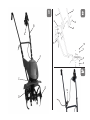
MONTAGGIO MANUBRI (Fig. 2 e 2/b) Inlare il tubo del manubrio inferiore (3) nei due fori del telaio (11) ssandolo con due viti (8), quattro
rondelle (9) e due dadi (10). Unire al tubo (3) i due manubri (1-2), separati dai particolari (6), ssati dalle viti (4), le rondelle (7) e le manopole (5)
IT
8

presenti nella busta accessori all’interno della scatola imballo.
Fig. 2/b) Inserire l’aggancio ferma lo (12) nel tubo stegola destro e successivamente fare passare il cavo di alimentazione come in gura.
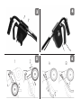
MONTAGGIO INTERRUTTORE (Fig. 3) Fissare l’interruttore inserendo i due perni in plastica nei fori della stegola come in gura. Richiudere
l’interruttore e ssarlo con le due viti autolettanti in dotazione nella busta accessori.
REGOLAZIONI
REGOLAZIONE MANUBRI (Fig. 2) Si può adattare l’altezza del manubrio superiore in base alle proprie esigenze. Questo è possibile
avvitando nei punti A o B i tubi (1 e 2). Per trasportare la motozappa su un automezzo, si possono smontare i 2 tubi del manubrio allentando le
manopole (5). N.B. Posizionare la motozappa ove non possa costituire pericolo per nessuno. Fissarla saldamente onde evitare il ribaltamento della
stessa con possibili danneggiamenti e fuoriuscita di olio dalla trasmissione.
REGOLAZIONE RUOTE DI TRASFERIMENTO (Fig. 5) E’ possibile regolare l’altezza delle ruote nelle posizione 1 (idonea per il
trasferimento) e nella posizione 2 (idonea per il lavoro). Per spostare le ruote dalla posizione 1 alla 2 fare scorrere il supporto ruote (S) nella direzione
indicata dalle frecce A, B e C. Per fare tornare la ruota in posizione 1 procedere nel modo inverso.
REGOLAZIONE PROFONDITA’ DI LAVORO (Fig. 6) Agendo sullo sperone si può regolare la profondità di lavoro in 2 posizioni : A e B.
Per spostare lo sperone dalla posizione A alla B farlo scorrere nella direzione indicata dalle frecce 1, 2 e 3. Per fare tornare lo sperone in A procedere
nel modo inverso. La posizione A corrisponde alla maggiore profondità di lavoro. La posizione B corrisponde alla minore profondità di lavoro. Per
lavori di sarchiatura ed eliminazione di erbe infestanti, combinare la posizione 1 (Fig. 5) delle ruote con la posizione A o B dello sperone (Fig. 6).
CONTROLLI PRIMA DELL’USO (Fig. 5 e 6) Vericare il livello olio della trasmissione: mettere la macchina in piano appoggiata allo
sperone in posizione B e le ruote in posizione 2. Svitare il tappo (part. T g.7) e controllare che l’olio sia al livello inferiore del foro. Il tappo di
riempimento e svuotamento corrisponde al livello dell’olio.
AVVIAMENTO DELLA MOTOZAPPA
Inserire la spina nella presa di corrente (230 Volt).
Fare passare il cavo nell’aggancio ferma lo ( part.12 g. 2/b)
Premere il pulsante (1) e tirare la leva (2) della g. 4.
Una volta avviato il motore rilasciare il pulsante (1) mantenendo premuta la leva (2). N.B. Il motore elettrico non ha, alla partenza, la stessa coppia di
un motore a scoppio; quando si avvia la motozappa è perciò necessario tenere la fresa alzata dal terreno facendo leva sullo sperone (Fig. 6).
Raggiunta la velocità massima di rotazione degli utensili è possibile iniziare il lavoro riportando la fresa a contatto con il terreno.
Per lo spegnimento della macchina e il disinnesto delle frese, rilasciare la leva (g. 4 part.2)
SOSTITUZIONE OLIO (Fig. 7)
In linea di massima si dovrebbe sostituire l’olio della trasmissione ogni 60 ore di lavoro.
Procedere come segue: allentare il tappo a vite ( part. T ), collocare la macchina in posizione inclinata e fare deuire l’olio. Introdurre l’olio nuovo tipo
SAE 80 per trasmissioni nella quantità di circa 0,11 litri. Per vericare il livello olio leggere il capitolo controlli prima dell’uso.
IT
9

MANUTENZIONE – PULIZIA (Fig. 8)
ATTENZIONE: prima di eseguire operazioni di pulizia o rimozione di corpi estranei bisogna sempre staccare ogni collegamento alla rete elettrica.
Montando le frese, la parte tagliente dei coltelli deve essere orientata nel senso di rotazione delle frese. Le 2 spine di ssaggio devono essere
orientate come indicato nella gura. Per rimuovere un corpo estraneo (sasso od altro) incastrato accidentalmente nelle frese, occorre slare la spina
(part. 1) e usare sempre i guanti di protezione. Pulire le frese, dopo ogni uso, dalla terra o dalla sporcizia usando un panno asciutto o una spazzola;
non usare mai in ogni caso acqua. Controllare lo stato delle frese e nel caso siano usurate o piegate, è necessario sostituirle. Controllare che tutti i
dadi e le viti siano serrati per garantire il funzionamento della macchina in condizioni di sicurezza.
DESCRIZIONE COMANDI (Fig. 1)
A- comando accensione. B- manubrio. C- etichetta CE. D- ruote trasporto. E- frese. F- guscio protezione motore.
CARATTERISTICHE TECNICHE
Trasmissione: vite senza ne ruota elicoidale (in bagno d’olio) per la trasmissione del moto all’albero porta frese. Tensione motore: 230 V, 50 Hz,
Potenza: 900 W.
Fresa : a zappette per larghezza di lavoro mm.340, diametro frese mm.250, velocità massima di rotazione 140 giri/minuto.
Peso della motozappa elettrica senza imballo: 15 Kg.
Dispositivo di sicurezza: tutte le motozappe sono dotate di un dispositivo antinfortunistico, Detto dispositivo causa il disinnesto automatico della
trasmissione quando si rilascia la relativa leva di comando.
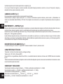
RUMORE AEREO E VIBRAZIONI
Valore di pressione acustica al posto di lavoro : Lpa = 73 dB (A) , valore d'incertezza nella misura K = ± 1 dB (A).
Valore di potenza acustica : Lwa = 85 dB (A) , valore d'incertezza nella misura K = ± 1,1 dB (A).
Valore di potenza acustica garantito : Lwa = 93 dB (A).
Vibrazioni alla stegola destra : ahw,x = 0,83 m/s² ; ahw,y = 2,47 m/s² ; ahw,z =0,60 m/s²
Valore medio rilevato : aw =2,68 m/s², , valore d'incertezza nella misura K = ± 1,34 m/s2.
ACCESSORI A RICHIESTA
Arieggiatore prato a molle: ideale per eliminare feltro e muschio da prati e giardini. L’arieggiatore prato a molle va ssato all’albero porta fresa con
una spina elastica dopo aver smontato la fresa standard.
Zavorra: da applicare sulla macchina per zappare più in profondità.
Rincalzatore ad ali sse : si usa per fare piccoli solchi nel terreno prima della semina.
E’ severamente vietato utilizzare accessori che non siano quelli sopraccitati; attenzione al senso di rotazione degli utensili.
IT
10

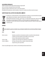
AVVERTENZE PER LA PROTEZIONE DELL’AMBIENTE
Non smaltire insieme ai riuti solidi urbani, ma raccogliere separatamente. Le sostanze ed i componenti elettrici contenuti nel presente
apparecchio ,se abbandonati o utilizzati in modo improprio, potrebbero rivelarsi dannosi per l’ambiente. Il simbolo del “ bidone della
spazzatura su ruote barrato con una barra nera rafgurata sotto il bidone” indica che il presente apparecchio e’ stato immesso in
commercio dopo il 13-8-2005 ed e’ soggetto a raccolta differenziata.
Ogni abuso verrà perseguito a norma di legge.
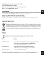
GUASTI
Prima di effettuare operazioni di assistenza, occorre interrompere l’erogazione della corrente (staccare la spina dalla presa di
corrente).
Guasto Rimedio
Il motore non funziona Controllare che la spina della motozappa sia inserita nella presa del cavo di alimentazione.
Controllare che la spina del cavo di alimentazione sia inserita nella presa di corrente.
Se il cavo di alimentazione è danneggiato : sostituirlo.
La fresa non gira Controllare che le frese siano ssate all’albero porta fresa.
Rimuovere corpi estranei, controllare eventuali danni alle frese.
La fresa lavora in modo non efciente Pulire la fresa ed eliminare corpi estranei.
Nel caso non si riesca a porre rimedio al guasto, rivolgersi ad un centro di assistenza autorizzato.
IT
11

List of contents
Introduction
Conditions of use
Identication data
Safety norms
Assembly
Adjustments
Maintenance
Technical Details
Noise and vibration level
Accessories
Fault
Serious risk for operator and
bystander safety.
INTRODUCTION
Dear Customer,
Firstly, we wish to thank you for having chosen our products and hope that the use of this machine will be
extremely satisfying for you and fully meet your expectations. This manual has been drawn up to allow your
to get to know your machine well and use it in safe and efcient conditions; please do not forget that it is an
integral part of the machine and keep it to hand to be consulted at all times and consign it with the machine if
you should sell or lend it to others.
Your new machine has been designed and manufactured to current standards and is safe and reliable if used in
full respect of the instructions contained in this manual (forecast use); any other use or failure to comply with the
instructions for safe use, maintenance and repair shall be considered as “improper use”, cause the warranty to
become null and void and relieve the Manufacturer from all responsibilities, with the user becoming responsible
for charges for damages or personal or third party injury.
If any slight differences are found between the description herein and the machine you own, please bear in mind
that due to continual product improvements, the information contained in this manual is subject to modication
without prior notice or obligatory updating, although the essential features for the purposes of safety and operation
remain unchanged. In the event of doubt, please contact your dealer.
IDENTIFICATION DATA (g. 1) : the label (C) with the unit data and the serial number is slicked to the
back of the frame (right). ATTENTION : the serial number of the machine is necessary to get technical support
or to order spare parts.
USE : the tiller is designed and manufactured in order to perform ground tilling operations according to the most
modern concept of biological cultivation. We do not recommend to hoe too deeply the soil to avoid damaging
the activity of micro-organisms. The tiller is suitable for small surfaces , to hoe, to spud and to eliminate weeds.
The tines have been designed to improve the soil cultivation. Any use, different from the above mentioned
ones is illegal and implies the warranty lost and also a serious danger for the operator and the people in the
neighbourhood. Use only original tools, accessories and spare parts.
SAFETY PRECAUTIONS & ACCIDENT PREVENTION MEASURES
Both on the machine body and in the present instructions booklet can be found indications
and notices linked to the a.m. symbol: in such cases please be careful because you can face
potential danger so it is recommended to use a special caution both for operator’s own sake
and bystanders’.
WARNING! Before assembly and putting the machine into operation, please read carefully the operating
instructions. Persons not familiar with such instructions are not authorized to use the machine.
Translation of original user instructions
EN
12

1. Persons who are not familiar with the operating manual, as well as children, adolescents under the age of 16 and persons under the inuence
of alcohol, drugs or medication must not operate the mower.
2. The unit was designed in order to be used by 1 trained operator only. The person using the mower is responsible for any accidents involving
other persons or their property. When operating the machine, the user should ensure that no others, particularly children, are standing in the
area (10 mt.).
3. Work only in daylight or in good articial light. Visibility is essential to guarantee safety conditions.
4. Before start to operate the unit, check carefully the feeding cable. In case the feeding cable shows to be damaged do not use the tiller:
verify rst the damage , make up for it : do not put the plug into the socket.
5. The section of the mains cable must be the same or higher if compared to class 05 RN. The value of the mains supply current to which the
machine is to be connected must correspond to the data shown on the machine label. For safety reasons, a 10A circuit breaker and a nominal
10/30 mA automatic cut-out must be installed on the power line.
6. Rotavator tines assembly disassembly, cleaning, servicing operations must be performed when the engine is switched off and the plug
removed from the socket.
7. Start the cultivator standing behind the handlebars. The operator’s position must be the same ( i.e. standing behind) at all times. Do not
work backwards, as there is risk of falling. Please walk, never run with the machine.
8. Do not touch/change safety/protection devices. If the operator releases the lever (Fig.4 - part.2), the motor/rotavator/tines must switch
off.
9. When the cultivator blades are in action, bear in mind the risk of injury to the feet: wear solid/suitable closed shoes and do not get near to
the cultivator blades.
10. Before starting the machine , check the area to be worked for foreign bodies and stones. Do not use the machine on ground containing
large stones.
11. In the case of an obstacle being hit which stops the machine, contact a service dealer to check it.
12. If the operator needs to lift up the blades from the ground for any reason, the machine must be switched off and the rotavator/tines must
be at a standstill. Do not leave the motor hoe unattended in the work area.
13. Do not store the motor hoe with plug inserted in the socket.
14. Do not use the motor hoe when it is raining, or in wet and damp weather. Do not sprinkle water on the machine and keep it protected from
humidity. Do not use the motor-hoe near ponds, swimming pool and water in general.
15. Modications or make-shift repairs on the machine are absolutely forbidden.
16. Please note that our company assumes no responsibility for damages due to: a) repairs made by unspecialized/unauthorized after sales
service centres and/or (b) use of other than ORIGINAL SPARE PARTS. The same conditions apply to the accessories.
ASSEMBLY INSTRUCTIONS: if the machine is not completely assembled do the following steps: at the purchase of the unit ( inside the carton
box packaging) is not completely assembled, please go on as follows :
HANDLEBARS ASSEMBLY (g. 2- 2b) :
a) Insert the lower handle (3) into the two holes of the frame (11).
b) x it with two screws (8), four washers (9) and two nuts (10).
EN
13

c) link the two handles (1-2) to the tube (3): make such operation adding the parts (6), xing with the screws (4), the washers (7) and the handles (5).
Fig. 2/b) Insert the wire cable holder (12) into the right handlebar tube, then make the wire to pass-by as shown in the picture.
All components are included in the packaging.
SWITCH ASSEMBLY (Fig. 3) : Fix the switch putting the 2 plastic pins into the holes of the handlebar as shown in the picture . Close the
switch opening-side and x it using the 2 self-tapping screws (in the accessories envelope).
ADJUSTMENT
HANDLEBARS ADJUSTMENT : (Fig. 2) upper handlebars can be adjusted in height. Such operation is possible by screwing up the tubes
(1 and 2) in points A or B. In order to transport the machine on a vehicle , you can disassemble the 2 handlebars by loosing the handles (5).
IMPORTANT - when you transport the machine on a vehicle you should position it where it won’t cause any damage to nobody. Block it tightly to avoid
the tiller to overturn, to get damaged and some oil leaks from the transmission.
TRANSPORT WHEELS ADJUSTMENT (Fig. 5) it is possible to adjust the wheels height into position 1( suitable for the transfer) and the
position 2 ( suitable for tilling). In order to move the wheels from position 1 to 2 make the wheel support (S) to slide towards the direction shown by
arrow A, B and C . To move the wheels back to position 1, make the same operations backwards.
DEPTH STAKE ADJUSTMENT : (Fig. 6) working depth can be adjusted. There are two positions : A and B.
To move the depth stake from position A to B slide it towards the direction shown by the arrows 1-2 and 3. To move it back to position A , please do
the same operation backwards.
Position A corresponds to the deeper working depth . Position B corresponds to a less deep working depth. To eliminate weeds, combine wheel position
1 (g.5) with position A or B of the depth stake (g.6).
CHECKS BEFORE START-UP (Fig. 5-6) : verify transmission oil level. Put the unit on a plain surface leaning on the depth stake in position
B and wheels in position 2. Unscrew the cap ( part T - g. 7), the oil must at the lower level of the hole. The lling/emptying corresponds to the oil level.
TILLER : HOW TO START
- Insert the plug into the socket 230 Volt,
- Make the wire to pass into the wire-holder (g.2/b part.12).
- Press the switch (1) and pull the lever (2) (g. 4).
- Once the engine is switched on, let the switch to go (1) making the lever to be still pressed (2). N.B. the electric engine is not showing , at the
beginning , the same torque of a piston engine ,
so it is necessary to make the rotavator to be up from the ground making the spur to play (g.6) . When you get to the tools max rotation speed it is
possible to start working , making the rotavator to touch the ground. As far as concerns the unit switching off and the rotavator stopping, slacken the
lever (g.4 part. 2).
CHANGE OIL (Fig.7) Generally speaking oil should be changed every 60 hours working. Go on as follows : loosen the screw-cap ( part. T)
and put the unit in on an inclined position and make the oil to ow out . Put in the unit some fresh oil (SAE 80) for a quantity about 0,11 lt. To verify oil
level read : CHECKS BEFORE START-UP.
EN
14

MAINTENANCE – CLEANING ( Fig. 8)
ATTENTION: before starting any work or maintenance on the machine, disconnect all electrical connections.
When you assemble the rotavator, the knives cutting part should be oriented clockwise.
The tightening pins must be xed as shown in picture (8).
In order to remove a stone or other object, embedded by chance into the tines, take the pins away (1). For such operation, please use protection
gloves.
Clean the cutters after use with a dry cloth or brush to remove mud and dirt; do not use water.
Check the cutter; if excessively worn or bent, they must be replaced.
Please check regularly that all nuts and screws are well tightened; this is to guarantee the safe working of the unit.
DRIVING CONTROLS DESCRIPTION (Fig. 1)
A) Switch and start button. B) handlebar. C) CE label. D) transport wheels. E) cultivator blade. F) protection electric motor.
TECHNICAL FEATURES
Transmission : worm-screw-helical gear (in oil-bath) for transmission to drive shaft.
Engine : voltage rating 230V, 50 Hz, Power 900 W.
Cultivator: with hoes, working width 340 mm., complete with safety case. Cutter diameter mm. 250. Max tiller speed: 140 RPM. Weight without
packaging 15 Kg.
Safety device: all cultivators are equipped with a safety device which disengages the transmission automatically when the corresponding control lever
is released.
NOISE AND VIBRATION LEVEL
Noise level when working in compliance : Lpa = 73 dB (A) , with a uncertainty value K = ±1 dB (A).
Measured sound power level : Lwa = 85 dB (A) , with a uncertainty value K = ±1,1 dB (A).
Measured sound power level guaranteed : Lwa = 93 dB (A).
Right side handlebar vibration: ahw,x = 0,83 m/s² ; ahw,y = 2,47 m/s² ; ahw,z = 0,60 m/s².
Level detected : aw = 2,68 m/s², uncertainty value K = ±1,34 m/s2.
ACCESSORIES ON REQUEST
De-Thatcher: it is good to eliminate the grass entanglement and musk from elds and gardens.
The de-Thatcher has to be xed on the hob spindle of the machine with an elastic plug, after the disassembling of the standard cutter.
Ballast: to hoe deeply.
Ridging plough: it is necessary to use it to cut small furrows before sowing.
It is strictly forbidden to use any other accessories except the ORIGINAL accessories.
ATTENTION! When you assemble the accessories check carefully the rotation direction of the accessories.
EN
15

SAFEGUARDING THE ENVIRONMENT
Do not dispose together with the solid urban waste, but collect and dispose separately. The components and the electrical wirings
which are contained in the present unit can be dangerous to the environment if they are improperly discarded or misused . The
symbol of a “wheeler- dustbin crossed and with a black bar shown under the dustbin” is showing that the present unit has been put
into the market after 13-8-2005 and it is subject to a separate collection . Any improper disposal or misuse will be prosecuted.
TROUBLESHOOTING
Before servicing the machine, disconnect the power supply (disconnect the plug from the power socket).
Problem Solution
The engine is not working check if the tiller plug is tting into the power cable socket.
check if the power cable plug is tting into the power socket.
if the power cable is damaged , please change it.
The rotavator is not turning check if the rotavators are tightened to the tines shaft.
make sure to remove any foreign body , check if any damage occured to the tines.
The rotavator is not efciently working clean the rotavator and remove any foreign body.
In case you are not able to remedy the defect/damage according to a.m. table, please contact an authorized service center only .
EN
16

Inhaltsverzeichnis
Einleitung
Identikationsdaten
Einsatzbedingungen
Sicherheitsmanahmen
Bedienungshinweise
Montage
Einstellung
Wartung
Technische Daten
Lärmemission
Zubehörteile
Störung
Schwere Gefahr für die
Unversehrtheit des Bedieners
und der Personen in der
Reichweite der Maschine.
Einleitung
Sehr geehrter Kunde,
Wir danken Ihnen, dass Sie sich für einen unserer Artikel entschieden haben und hoffen, dass dieser voll und
ganz Ihren Erwartungen entspricht. Die vorliegende Gebrauchsanleitung soll Ihnen dabei helfen, den Betrieb
Ihres Geräts zu verstehen und dieses unter Berücksichtigung Ihrer persönlichen Sicherheit zu verwenden.
Die Gebrauchsanleitung ist Teil des Geräts: Sie sollten sie daher so aufbewahren, dass Sie jederzeit darin
nachschlagen können.
Sollten Sie das Gerät verleihen oder aus sonstigen Gründen an Dritte übergeben, muss die Gebrauchsanleitung
ebenfalls übergeben werden.
Das von Ihnen erworbene Gerät wurde den geltenden Vorschriften entsprechend geplant und hergestellt
und garantiert Ihnen daher unter den in vorliegender Anleitung beschriebenen Bedingungen (Vorgesehener
Gebrauch) einen sicheren Betrieb.
Jeder andersartige Einsatz des Geräts, bzw. das Nichtbeachten der Hinweise bezüglich Sicherheit, Wartung
und Reparatur ist als unsachgemäßer Gebrauch des Geräts zu verstehen und hat den Gültigkeitsverfall der
Garantie zur Folge. Der Hersteller kann für Sach- oder Personenschäden, die Folge eines unsachgmäßen
Gebrauch des Geräts sind, nicht haftbar gemacht werden.
Sollten Sie einige Abweichungen zwischen den Angaben der vorliegenden Anleitung und dem von Ihnen
erworbenen Gerät feststellen, so berücksichtigen Sie bitte, dass der Hersteller zur technischen
Aktualisierung seiner Produkte ohne Vorankündigung Änderungen daran vornehmen kann. Die grundlegenden
Sicherheits- und Betriebsnormen werden durch eine derartige Aktualisierung jedoch nicht beeinusst und sind
daher unbedingt zu befolgen. Wenden Sie sich im Zweifelsfall bitte an Ihren Verkäufer. Wir wünschen Ihnen
eine gute Arbeit.
IDENTIFIKATIONSDATEN (Abb.1) Das Etikett (C) mit den Daten der Maschine und der Serien-Er. Ist auf
der Rückseite rechts am Gestell aufgeklebt. Anmerkung Bei den etwaigen Anforderungen des Kundendienstes
oder beim Bestellen von Ersatzteilen ist immer die Seriennummer der fraglichen Motorhacke anzugeben.
EINSATZBEDINGUNGEN – EINSATZBESCHRÄNKUNGEN
Die Motorhacke ist entwickelt und konstruiert worden, um den Boden nach den modernsten Konzepten der
biologischen Landwirtschaft zu hacken. Der Boden sollte nicht in größerer Tiefe bearbeitet werden, weil sonst
die Tätigkeit der Mikroorganismen gestört werden könnte. Die Motorhacke eignet sich für kleinere Flächen, denn
sie fräst und hackt, wobei das Unkraut entfernt wird. Die Form der Fräsmesser ist speziell so ausgelegt, dass
der Boden besser bearbeitet wird. Jeder andere Einsatz als der oben beschriebene ist unzulässig und bedingt
außerdem den Verfall der Garantie. Er stellt zudem eine schwere Gefährdung des Bedieners und der Personen
in der Reichweite der Maschine dar. Die Motorhacke darf nur mit Originalgeräten und Originalersatzteilen
betrieben werden.
Übersetzung der originalen Betriebsanleitung
DE
17

SICHERHEITS- UND UNFALLVERHÜTUNGSBESTIMMUNGEN
Auf der Maschine und in diesem Handbuch stehen einige Meldungen und Angaben, die von diesem Signal begleitet werden. Sie
geben das Vorhandensein einer potentiellen Gefahr an, so dass es angemessen ist, der eigenen Sicherheit und der Sicherheit derer
wegen, die sich in der Reichweite der Maschine benden könnten, eine besondere Vorsicht walten zu lassen.
SICHERHEITSMAßNAHMEN
Achtung: Vor der Montage und Inbetriebnahme unbedingt Bedienungsanweisung beachten! Personen, die mit der Gebrauchsanweisung nicht
vertraut sind, dürfen das Gerät nicht benutzen.
1. Personen, die mit der Bedienungsanleitung nicht vertraut sind, Kinder, Jugendliche unter 16 Jahren, sowie Personen unter Alkohol-,
Drogen- oder Medikamenteneinuss dürfen das Gerät nicht bedienen.
2. Diese Maschine ist entwickelt worden, damit sie von einem einzelnen ausgebildeten Benutzer verwendet werden kann. Vor Benutzung
sicherstellen, dass keine Kinder in der Nähe sind (10 Meter).
3. Bei Tageslicht arbeiten. Eine einwandfreie Sicht ist Grundvoraussetzung für ein sicheres Arbeiten.
4. Vor dem Gebrauch den Zustand des Speisekabels überprüfen. Sollte es beschädigt sein, die Motorhacke nicht verwenden und sicherstellen,
dass der Stecker nicht in der Dose steckt. Erst dann nach dem Schaden suchen.
5. Das Speisekabel muss einen Querschnitt gleich oder höher als Klasse 05RN haben. Die Angaben über Netzspannung und Stromart am
Typenschild müssen mit den Daten Ihres Elektronetzes übereinstimmen. Zur Absicherung muss ein Leitungs-Schutzschalter 10 A sowie ein
Fehlerstromschutzschalter mit einen Nennfehlerstrom von 10/30 mA installiert sein.
6. Das Montieren und Abmontieren der Fräsen, deren Reinigung, sowie alle Wartungseingriffe dürfen nur bei abgeschaltetem Motor und
ausgestecktem Stecker erfolgen.
7. Beim Anlassen der Motorhacke hinter den Sterzen bleiben. Auch beim Fräsen muss der Bediener diese Position beibehalten. Gehen Sie
nicht rückwärts- Stolpergefahr. Nicht mit den gerät laufen.
8. Nicht eigenmächtig an den Schutzverkleidungen und Sicherheitssystemen eingreifen. Beim Loslassen des Hebels (Abb.4 Teil 2) müssen
der Motor die Fräse anhalten.
9. Die laufenden Fräsen sind gefährlich für die Füße. Zweckdienliche Schuhe tragen und die Füße fernhalten.
10. Herumliegende Fremdkörper (Steine, Holz, usw.) vor der Bodenbearbeitung entfernen. Auch auf eventuelle andere Gegenstände achten,
die beim Fräsen vorkommen können. Das Gerät ist nicht für grobsteinigen Untergrund geeignet.
11. Stößt man an einem Hindernis an, das die Maschine blockiert, vom Kundendienst kontrollieren lassen.
12. Bevor man die Fräsen vom Boden anhebt und versetzt, die Motorhacke abschalten und warten, daß das Werkzeug anhält. Lassen Sie
die Garten- Pegehacke nie unbeaufsichtigt am Arbeitsplatz liegen.
13. Die Motorhacke nach dem Gebrauch nicht mit eingestecktem Stecker wegstellen.
14. Die Motorhacke nicht mit Wasser bespritzen und vor Feuchtigkeit schützen. Arbeiten Sie mit der Garten-Pegehacke nicht in oder an
Gartenteichen, Schwimmbädern oder Gewässern.
15. Jegliche eigenmächtigen Veränderungen oder Umbauten an der Garten-Pegehacke sind verboten.
16. Wir weisen darauf hin, dass wir bei Schäden wegen a) Reparaturen, die nicht von Fachpersonal oder autorisierten Kundendiensten
vorgenommen wurden oder b) Verwendung anderer als der ORIGINAL-ERSATZTEILE, keine Haftung übernehmen. Für die Zubehörteile
gelten dieselben Bedingungen.
DE
18

MONTAGE Mit Ausnahme anderweitiger Vereinbarungen wird die Motorhackmaschine abmontiert, in einer zweckdienlichen Verpackung geliefert.
Die Motorhackmaschine wie folgt zusammenbauen.
MONTAGE DER LENKHOLME (Abb. 2-2/b) Das Tragrohr der Lenkholme (3) in die beiden Löcher des Gestells (11) stecken und mit den
beiden Schrauben (8), den vier Unterlegscheiben (9) und den zwei Muttern (10) befestigen. Die beiden Lenkholme (1-2), die durch die Teile (6)
getrennt sind, am Rohr (3) anschließen. Diese werden mit den Schrauben (4), den Unterlegscheiben (7) und den Handgriffen (5) befestigt, die sich
in dem Beutel benden, der im Verpackungskarton liegt.
Fig. 2/b) Den Drahthalter (12) in das rechte Holmrohr einsetzen und das Kabel gemäß der Abbildung einführen.
MONTAGE DES SCHALTERS (Abb. 3) Den Schalter durch die Einführung der zwei Kunststoffzapfen in die Löcher des Holms nach
der Abbildung befestigen. Den Schalter wieder schließen und durch die zwei in der Zubehörtüte vorhandenen selbstschneidenden Schrauben
befestigen.
EINSTELLUNG
EINSTELLUNG DER LENKHOLME (Abb. 2) Man kann die Höhe der Lenkholme an seine Erfordernisse anpassen. Dies ist möglich,
indem man die Rohre (1 und 2) an den Stellen A oder B anschraubt.
Um die Motorhacke mit einem Fahrzeug zu transportieren, kann man die 2 Rohre der Lenkholme abnehmen, indem man die Griffe (5).
Wenn man die Motorhacke mit einem Fahrzeug transportiert, ist sie so anzuordnen, dass sie für niemanden eine Gefahr darstellt. Man muss sie sicher
verankern, damit sie nicht umkippen kann, denn dabei könnte sie beschädigt werden und es könnte Kraftstoff und Öl aus dem Getriebe auslaufen.
EINSTELLUNG DER TRANSPORTRÄDER (Abb. 5) Man kann die Höhe der Räder auf die Position 1 (zum Transport geeignet) und auf
die Position 2 (für die Arbeit geeignet) einstellen. Um die Räder aus der Position 1 in die Position 2 zu bringen, muss man den Radträger (S) in der
Richtung der Pfeile A, B und C gleiten lassen. Um die Räder wieder in die Position 1 zurückzubringen, in der umgekehrten Weise vorgehen.
EINSTELLUNG DER ARBEITSTIEFE (Abb. 6) Mit dem Sporn kann man die Arbeitstiefe auf 2 Positionen einstellen: A und B.
Um den Sporn aus der Position A in die Position B zu bringen, muss man ihn in der Richtung der Pfeile 1-2 und 3 gleiten lassen. Um den Sport wieder
in die Position A zurückzubringen, ist in der umgekehrten Reihenfolge vorzugehen. Die Position A entspricht der größeren Arbeitstiefe.
Die Position B entspricht der geringeren Arbeitstiefe. Zum Hacken und Beseitigen von Unkraut die Position 1(Abb.5) der Räder mit der Position A
oder B des Sporns (Abb. 6) kombinieren.
KONTROLLEN VOR DEM GEBRAUCH (Abb. 5 und 6) Den Ölstand des Getriebes prüfen: Die Maschine auf einer ebenen Fläche auf
dem Sporn in der Position und den Rädern in der Position 2 abstellen. Den Stopfen (Teil T Abb.) losschrauben und sicherstellen, dass das Öl bis zur
unteren Lochkante steht. Der Füll- und Entleerstopfen entspricht dem Ölstand.
DE
19

STARTEN DER MOTORHACKE
- Stecker in Steckdose (230 Volt) stecken.
- Das Kabel in den Drahthalter und dann (Abb.2/b Teil 12 ).
- Den Knopf (1) drücken und den Hebel ziehen (2). (Abb. 4)
- Nach dem Motoranlaß den Knopf (1) freigeben, indem man den Hebel (2) gedrückt hält. ANMERKUNG: Beim Starten hat der Elektromotor nicht das
selbe Drehmoment eines Explosionsmotors; deshalb muss man beim Anlassen der Motorhacke die Fräse vom Boden
gehoben halten, indem man den Hebel auf den Bremssporn ansetzt (Abb.6).
Nachdem man die maximale Drehungsgeschwindigkeit der Werkzeuge erreicht hat, kann man
mit der Arbeit anfangen und die Fräse mit dem Boden wieder in Berührung bringen. Zum Abstellen der Maschine und Abschaltung der Fräsen den
gelben Hebel freilassen (Abb.4 Teil.2).
ÖLWECHSEL ( Abb.7) Das Öl ist grundsätzlich alle 60 Betriebsstunden zu wechseln. Wie folgt vorgehen: den Schraubverschluss lockern
(Teil.T), die Maschine geneigt stellen und das Öl herausließen lassen.
WARTUNG – REINIGUNG ( Abb.8 )
Vor allen Pege- und Wartungsarbeiten Netzstecker ziehen abklemmen. Wenn man die Hackmesser montiert, muss die Schneide der Messer in der
Laufrichtung der Hacksterne zeigen.
Die Befestigungsstifte müssen so ausgerichtet sein, wie es in der Abb.8 zu sehen ist. Um einen Fremdkörper (Stein oder anderes) zu beseitigen, der
sich in den Hackmessern verkantet hat, muss man den Stift (Teil. 1). In beiden Fallen sind Schutzhandschuhe zu tragen.
Reinigen Sie die Fräswerkzeuge nach jedem Gebrauch von Erd- und Schmutzresten.
Benutzen Sie hierzu ein trockenes Tuch oder eine Bürste – keinesfalls Wasser.
Prüfen Sie die Fräswerkzeuge auf einwandfrei en Zustand. Abgenützte oder verbogene Fräswerkzeuge müssen gewechselt werden.
Sicherstellen, dass alle Muttern und Schrauben fest sitzen, um den Betrieb der Maschine unter sicheren Voraussetzungen zu gewährleisten.
BESCHREIBUNG DER STELLTEILE (Abb. 1)
A – Zündungsbetätigung. B – Lenkholme. C – Etikette CE. D – Transporträder. E – Hackmesser. F – Elektromotor Deckel.
TECHNISCHE EIGENSCHAFTEN
Antrieb : Schnecke -Schrägzahnrad (in Ölbad) zum Antrieb der Fräsenwellen.
Motorspannung : 230V, 50 Hz . Leistung 900 W
Fräse : Mit Hacken, Arbeitsbreite 340 mm, komplett mit Schutzgehäuse, Durchmesser 250 mm. Max. Fräsendrehzahl ca. 140 Upm. Gewicht
Verpackung einschließlich 15 Kg.
Sicherheitsvorrichtung : Alle Motorhackmaschinen sind mit Unfallverhütungsvorrichtung ausgestattet.
Durch diese Vorrichtung wird beim Loslassen des Steuerhebels automatisch der Antrieb ausgekuppelt.
LÄRMEMISSION UND VIBRATIONEN
Der Wert des Schalldrucks am Arbeitsplatz beträgt :Lpa = 73 dB (A) , Messunsicherheit K = ±1 dB (A).
DE
20
La page est en cours de chargement...
La page est en cours de chargement...
La page est en cours de chargement...
La page est en cours de chargement...
La page est en cours de chargement...
La page est en cours de chargement...
La page est en cours de chargement...
La page est en cours de chargement...
La page est en cours de chargement...
La page est en cours de chargement...
La page est en cours de chargement...
La page est en cours de chargement...
-
 1
1
-
 2
2
-
 3
3
-
 4
4
-
 5
5
-
 6
6
-
 7
7
-
 8
8
-
 9
9
-
 10
10
-
 11
11
-
 12
12
-
 13
13
-
 14
14
-
 15
15
-
 16
16
-
 17
17
-
 18
18
-
 19
19
-
 20
20
-
 21
21
-
 22
22
-
 23
23
-
 24
24
-
 25
25
-
 26
26
-
 27
27
-
 28
28
-
 29
29
-
 30
30
-
 31
31
-
 32
32


EUROSYSTEMS 01 Mode d'emploi
- Catégorie
- Mini motoculteurs
- Taper
- Mode d'emploi
dans d''autres langues
- italiano: EUROSYSTEMS 01 Istruzioni per l'uso
- English: EUROSYSTEMS 01 Operating instructions
- español: EUROSYSTEMS 01 Instrucciones de operación
- Deutsch: EUROSYSTEMS 01 Bedienungsanleitung