
1
INSTRUCTION MANUAL
LIGHT FIXTURE
IMPORTANT SAFETY INSTRUCTIONS
CAUTION: Make sure power is turned off at the electrical panel box before beginning
your installation. Turning the power off at the wall switch is not sufficient to prevent
electrical shock.
INSTRUCTIONS PERTAINING TO RISK OF FIRE OR INJURY TO PERSONS
1. Read all instructions prior to beginning the installation process.
2. Do not install this lighting system in or near a wet location.
3. CAUTION: HOT SURFACE. Keep away from curtains and other combustible
materials.
4. THE BULB IS HOT! Make sure that the bulb is cool before re-lamping the fixture.
5. This fixture is intended to be mounted to a 4"square x 2-1/8"deep metal octagon
outlet box. The box must be directly supported by the building structure.
6. Remove the fixture and the mounting packages from the box and make sure that no
parts are missing by referencing the illustrations on the installation instructions.
NOTE: All electrical connections must be in accordance with local codes and the
National Electrical Code. If you are unfamiliar with methods of installing electrical
wiring, secure the services of a qualified licensed electrician.
SAVE THESE INSTRUCTIONS
TOOLS NEEDED (not included): Ladder, Safety goggles, Gloves, Flathead
screwdriver, Phillips screwdriver, Electrical tape, Wire cutters, Bulb.
ASSEMBLY INSTRUCTIONS (AS SHOWN IN DIAGRAM):
1. Make sure the main power to the circuit is OFF.
2. Remove the mounting bracket assembly from the canopy and install mounting
bracket to existing outlet box with outlet box screws provided.
3. Pull wires through mounting plate.
4. Wrap the ground wire under and around the ground screw which is marked “GND”,
and fasten the ground screw to make sure the ground wire is securely connected.
5. Make the electrical connections (Required Supply Circuit: 120V 60Hz):
a. Connect the white wire(s) from the fixture to the white wire of the supply circuit.
b. Connect the black wire(s) from the fixture to the black wire of the supply circuit.
c. Connect the green colored (or bare copper) wire to the grounding conductor of the
supply circuit.
d. Use U.L. Listed wire connectors suitable for the size, type and number of
conductors. No loose strands or loose wires should be present.
e. Secure wire connectors with U.L. Listed electrical tape.
f. Carefully tuck connected wires back into the outlet box.
6. Attach the canopy onto the mounting bracket and tighten the canopy screw to secure
the fixture.
7. Secure the threaded tube into the coupler of fixture body and tighten it with the hex
nut of threaded tube.
EC7733OB4

2
8. Install the light bulb (bulb sold separately).
9. Place the diffuser on to the threaded tube and tighten with the hex nut, then secure
with the decorative cap.
RELAMPING THE LIGHT BULB(S)
1. Turn off the power to the light fixture.
2. Loosen the decorative cap, and remove the bottom cap, then loosen the hex nut and
remove the diffuser.
3. Remove the old light bulb(s) and install the new light bulb(s).
4. Replace the diffuser and tighten with the hex nut, then replace the bottom cap and
tighten with the decorative cap.
5. Restore power to the light fixture.
CAUTION: Refer to the re-lamping label located on the fixture. Do not exceed
recommended wattage.
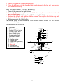
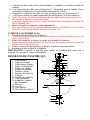
ASSEMBLY DIAGRAM
1. Outlet box
2. Wire connector
3. Neutral (White) wire
4. Ground (bare) wire
5. Live (Black) wire
6. Ground screw
7. Mounting bracket
8. Outlet box screw
9. Canopy
10. Canopy screw
11. Thread tube
12. Bulb (sold separately)
13. Diffuser
14. Hex nut
15. Bottom cap
16. Decorative cap
3
2
1
16
15
14
13
12
11
10
9
8
6
7
5
4

3
MANUEL D’INSTRUCTIONS
PLAFONNIER À LAMPES
CONSIGNES DE SÉCURITÉ IMPORTANTES
ATTENTION : Avant d’entamer l'installation, débrancher l'alimentation électrique en
fermant le disjoncteur ou en retirant le fusible approprié dans la boîte à fusibles. Couper
l'alimentation électrique en éteignant l'interrupteur mural est insuffisant pour prévenir
les chocs électriques.
INSTRUCTIONS RELATIVES AU RISQUE D’INCENDIE OU DE BLESSURES
CORPORELLES
1. Bien lire toutes les instructions avant d’entamer l’installation.
2. Ne pas installer ce système d'éclairage dans ou à proximité d’un endroit mouillé.
3. ATTENTION : SURFACE BRÛLANTE. La garder éloignée des rideaux ou de
tout autre matériau combustible.
4. L’AMPOULE EST CHAUDE! S’assurer que l’ampoule est froide avant de la
changer.
5. Ce plafonnier est conçu pour être fixé à une boîte de sortie de courant métallique
octogonale de 10,16 cm (4 po) de largeur et d'une profondeur de 5,40 cm (2 1/8 po).
La boîte doit être directement supportée par la structure du bâtiment.
6. Retirez l’appareil d’éclairage et les emballages de pièces de montage de la boîte;
assurez-vous qu’aucune pièce ne manque en vous reportant aux illustrations des
instructions d’installation.
REMARQUE : Tous les branchements électriques doivent être conformes aux codes
locaux et au Code national de l’électricité. En cas de doute quant aux méthodes
d’installation de câblage électrique, réserver les services d’un électricien accrédité
qualifié. CONSERVER CES INSTRUCTIONS
OUTILS REQUIS (non compris): Escabeau, Lunettes de sécurité, Gants,
Tournevis plat, Tournevis cruciform, Ruban isolant, Coupe-fils, Ampoule.
INSTRUCTIONS D’ASSEMBLAGE (TELLES QU’ILLUSTRÉES
DANS LE DIAGRAMME) :
1. S’assurer que l’alimentation principale est COUPÉE.
2. Retirez le support de fixation de la monture et fixer la traverse à la boîte de sortie
de courant au moyen des vis fournies.
3. Tirer les câbles à travers l'orifice de la traverse.
4. Enrouler le fil de mise à la terre sous et autour de la vis de mise à la terre qui est
marquée «GND», et serrer la vis de mise à la terre pour assurer que le fil de mise à
la terre est bien connecté
5. Effectuer les branchements électriques (Circuit d’alimentation requis: 120V, 60Hz):
a. Relier le(s) fil(s) blanc(s) du plafonnier au fil blanc du circuit d’alimentation.
b. Relier le(s) fil(s) noir(s) du plafonnier au fil noir du circuit d’alimentation.
c. Relier le fil vert (ou le fil nu en cuivre) au fil de mise à la terre du circuit

4
d’alimentation.
d. Utiliser des capuchons de connexion homologués UL qui conviennent aux format,
type et nombre de conducteurs. Aucun brin ni fil ne doit être desserré.
e. Sécuriser les capuchons de connexion au moyen de ruban isolant homologué U.L.
f. Replier délicatement les fils raccordés à l’intérieur de la boîte de sortie.
6. Attach the canopy onto the mounting bracket and tighten the canopy screw on to the
mounting bracket to secure the fixture.
7. Secure the threaded tube into the coupler of fixture body and tighten it with the hex
nut of threaded tube.
8. Installez l'ampoule électrique (la bombilla se vende por separado).
9. Place the diffuser on to the threaded tube and tighten with the hex nut, then place
the bottom cap on it and tighten with the decorative cap.
REMPLACER LA (LES) AMPOULE(S)
1. Couper l’alimentation électrique du plafonnier.
2. Loosen the decorative cap, and remove the bottom cap, then loosen the hex nut and
remove the diffuser.
3. Retirer l’(les) ancienne(s) ampoule(s) et installer la (les) nouvelle(s) ampoule(s).
4. Replace the diffuser and tighten with the hex nut, then replace the bottom cap and
tighten with the decorative cap.
5. Remettre le plafonnier sous tension.
ATTENTION: Consulter l’étiquette de remplacement de l’ampoule située sur
l’appareil. Ne pas dépasser la puissance recommandée.
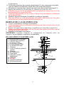
DIAGRAMME D’ASSEMBLAGE :
1. Boîte de sortie de courant
2. Capuchon de connexion
3. Fil neutre (Blanc)
4. Fil de mise à la terre
5. Fil sous tension (Noir)
6. Vis de mise à la terre
7. Traverse
8. Vis de la boîte de sortie de
courant
9. Monture
10. Vis de monture
11. Tige filetée
12. Ampoule (vendue
séparément)
13. Diffuseur
14. Hex nut
15. Capuchon inférieur
16. Bouchon décoratif
3
2
1
16
15
14
13
12
11
10
9
8
6
7
5
4

5
MANUAL DE INSTRUCCIONES
LÁMPARA DE LUCES
INSTRUCCIONES DE SEGURIDAD IMPORTANTES
PRECAUCIÓN: Antes de empezar la instalación corta el suministro de electricidad,
apagando el cortacircuitos o retirando el fusible correspondiente en la caja de fusibles.
Cortar el suministro de electricidad con el interruptor de luz no es suficiente para evitar
una descarga eléctrica.
INSTRUCCIONES SOBRE RIESGOS DE INCENDIO O LESIONES FÍSICAS
1. Lee todas las instrucciones antes de comenzar la instalación.
2. No instalar este sistema de iluminación en un lugar húmedo o cerca de él.
3. PRECAUCIÓN: LA SUPERFICIE ESTÁ CALIENTE. Mantener lejos de las
cortinas y otros materiales combustibles.
4. ¡LA BOMBILLA ESTÁ CALIENTE! Asegúrate de que la bombilla esté fría
antes de cambiarla.
5. Esta lámpara se debe montar en una caja eléctrica octogonal de metal de 5,39 cm
de profundidad y 10,16 cm². La caja debe estar directamente apoyada en la
estructura de la vivienda.
6. Retire el accesorio de iluminación y los paquetes de montaje de la caja y asegúrese
de que no falte ninguna de las partes tomando como referencia las ilustraciones
que aparecen en las instrucciones de instalación.
NOTA: Todas las conexiones se deben hacer conforme con el Código Nacional de
Electricidad y con los códigos de electricidad locales. Si no estás familiarizado con los
métodos de instalación del cableado eléctrico, contrata los servicios de un electricista certificado y
calificado. GUARDA ESTAS INSTRUCCIONES
HERRAMIENTAS NECESARIAS (no incluidas): Escalera, Gafas protectoras,
Guantes, Destornillador plano, Destornillador Phillips, Cinta de electricista, Pelacables,
Bombilla.
INSTRUCCIONES DE ENSAMBLAJE (COMO SE MUESTRAN
EN EL DIAGRAMA):
1. Asegúrate de que la electricidad principal que va al circuito está APAGADA.
2. Retira el ensamblaje del soporte de montaje de la cubierta y instala el soporte de
montaje en la caja eléctrica existente con los tornillos incluidos.
3. Saca los cables a través del orificio del soporte de montaje.
4. Enrolla el cable a tierra debajo y alrededor del tornillo a tierra que está marcado
como “GND”, y sujeta el tornillo a tierra para garantizar que el cable a tierra esté
firmemente conectado.
5. Haz las conexiones eléctricas(Circuito de alimentación requerido: 120 V 60 Hz):
a. Conecta el (los) cable(s) blanco(s) de la lámpara al cable blanco del circuito de
energía.
b. Conecta el (los) cable(s) negro(s) de la lámpara al cable negro del circuito de
energía.

6
c. Conecta el cable verde (o de cobre desnudo) al conductor a tierra del circuito de
energía.
d. Usa conectores de cable con clasificación UL adecuados para el tamaño, tipo y
cantidad de conductores. No debe haber cables sueltos o flojos.
e. Asegura los conectores de cable con cinta de electricista con clasificación UL.
f. Coloca con cuidado los cables conectados de vuelta dentro de la caja eléctrica
6. Attach the canopy onto the mounting bracket and tighten the canopy screw on to
the mounting bracket to secure the fixture.
7. Secure the threaded tube into the coupler of fixture body and tighten it with the hex
nut of threaded tube.
8. Instala la Bombilla (ampoule vendue séparément).
9. Place the diffuser on to the threaded tube and tighten with the hex nut, then place
the bottom cap on it and tighten with the decorative cap.
CAMBIAR LA(S) BOMBILLA(S)
1. Desconecta la electricidad de la lámpara.
2. Loosen the decorative cap, and remove the bottom cap, then loosen the hex nut and
remove the diffuser.
3. Retira la(s) bombilla (s) vieja(s) e instala la(s) bombilla(s) nueva(s).
4. Replace the diffuser and tighten with the hex nut, then replace the bottom cap and
tighten with the decorative cap.
5. Vuelve a colocar la tapa inferior y el difusor, y aprieta la tapa decorativa.
6. Restablece la electricidad de la lámpara.
PRECAUCIÓN: Consulta la etiqueta para cambio de bombilla que viene con la
lámpara. No excedas el vataje recomendado.
DIAGRAMA DE ENSAMBLAJE:
1. Caja eléctrica
2. Conector de cable
3. Cable neutro (blanco)
4. Cable a tierra(pelado)
5. Cable vivo (negro)
6. Soporte de montaje
7. Tornillo a tierra
8. Tornillo del pabellón
9. Cubierta
10. Tornillo del pabellón
11. Tubo Enroscado
12. Bombilla (Vendida
por Separado)
13. Difusor
14. Hex nut
15. Tapa inferior
16. Casquillo decorativo
3
2
1
16
15
14
13
12
11
10
9
8
6
7
5
4
-
 1
1
-
 2
2
-
 3
3
-
 4
4
-
 5
5
-
 6
6


