Starblitz Kit studio 2x400W Le manuel du propriétaire
- Catégorie
- Accessoires pour appareil photo
- Taper
- Le manuel du propriétaire
Ce manuel convient également à

EN
FR
ES
SHARK200/SHARK400
User guide /
Mode d’emploi /
Manual de usuario
www.starblitz.fr


1
EN
FR
ES
Compact ash unit
STARBLITZ® SHARK200/SHARK400
User guide
Thanks for selecting the Starblitz® SHARK. Please read these instructions carefully
and keep them handy for your reference.
The Starblitz® SHARK is a powerful, self contained AC powered, electronic ash unit.
This Flash provides exibility in positioning and ease of use.
Please ensure that you are completely familiar with the operations and features of
your new ash before using it.
Table of Contents
Safety Notes ............................................................................................................. 2
Content of Carton .................................................................................................... 2
Preparing Your Flash for Use ................................................................................... 3
Power Supply Connection ....................................................................................... 3
Light Holder with Umbrella Hole ........................................................................... 5
Operating the Modeling Lamp ............................................................................... 5
Triggering the Flash ................................................................................................ 5
Audible Beep Settings ........................................................................................... 10
Flash Output .......................................................................................................... 10
Changing the Flash Tube .......................................................................................11
Changing the Fuse .................................................................................................12
Overheating Protection ........................................................................................ 12
Flash Capacitor Preventative Maintenance ......................................................... 12
Specications ......................................................................................................... 13

2
EN
FR
ES
Safety Notes
Do not use your ash in an environment where moisture or ammable vapour is
likely to come in contact with the unit.
A re hazard exists if ammable materials are placed in close proximity to either
the ash tube or the modelling lamp when the unit is in use.
Do not restrict air vents while in use.
Always switch o and disconnect from the main power before changing fuse, mo-
delling lamp or ash tube.
Avoid placing cables where they can be tripped over. Protect from heavy, sharp ob-
ject or hot object, which may cause damage. Replace damaged cables immediately.
Never use a unit with damaged covers, mouldings, ash tubes or modeling lamp.
If the unit is dropped or damaged in any way always have it checked out before using.
Use a blower brush or clean facial tissue to remove dust and moisture from the
modelling lamp and the ash tube. Do not apply any uids to the modelling lamp
and the ash tube.
Turn the power o and unplug the power cord if the ash is not going to be used
for a while.
Do not ash over 8 times in a minute at full.
We recommend charging the ash unit for 2 hours prior to initial use and after an
extended period of inactivity (2 to 3 weeks).
Due to the high voltage circuitry inside the unit, do not attempt to disassemble
the ash yourself.
Keep out of reach of children.
Content of Carton
110V-120V or 220-240V Flash unit with ash tube
75W Modeling lamp
Standard reector (with or without standard reector)
Protective cover
Power cable
4.5V Sync cable
User guide

3
EN
FR
ES
Preparing Your Flash for Use
1. Select a stand or support system of suitable weight and dimensions to ensure
stable operation of the unit.
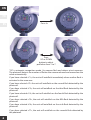
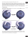
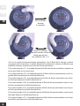
2. Install Reector / Protective Cap and Modeling Lamp
- To remove plastic protective cap o, push the latch knob back towards the rear of
the unit and rotate the plastic protective cap anti clockwise.
- Install the modeling lamp by inserting it into the socket.
- Install the reector where the protective cap was before. Align the three pegs on
the reector with the three slots, press the reector in and rotate clockwise until it
locks in place.
- To remove, push the latch knob back towards the rear of the unit and rotate the
reector anti-clockwise.
Do not touch the lamp with your bare hands. Oil residue from your ngers can
cause the surface of the lamp to heat unevenly and explode. Use white cotton gloves
or a clean cloth.
Take care not to damage the ash tube assembly when tting or removing reec-
tors or soft boxes. The ash tube is very delicate; avoid unnecessary handling of the
ash tube.
Always switch o and disconnect from the main supply before tting and chan-
ging reectors, inserting the modeling lamp or replacing the ash tube.
Standard conguration of softbox for Starblitz® SHARK studio ash is SB-030
50*70cm. We do not recommend to install SB-030 square softbox bigger than
60*90cm or SB-038 octagon softbox bigger than diameter 80 cm, or beauty dish
bigger than diameter 460mm.
Power Supply Connection
Use only the mains leads supplied to connect to the main power.
Before plugging the power cord into the wall socket, make certain that the power
switch is set to the OFF (“0” position).

4
EN
FR
ES
2
3
4
5
6
7
8
9
10
11
12
1
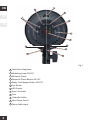
Fig.1
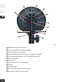
1
Flash Power Regulator
2
Modelling Lamp ON/OFF
3
Photocell (Slave)
4
Photocell (Slave) Button ON/OFF
5
Ready Flash Beeper Button ON/OFF
6
Test Button
7
LED Display
8
Sync Cord Input
9
Fuse
10
Umbrella Holder
11
Main Power Switch
12
Power Cable Input

5
EN
FR
ES
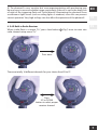
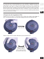
Light Holder with Umbrella Hole
An umbrella with a handle diameter of 8-10mm can be rmly secured in the umbrella
holder. Do not over tighten the screw of the umbrella holder to avoid squashing the
shaft of the umbrella.
When the standard reector is used, t the umbrella in the hole of the reector.
Operating the Modelling Lamp
To turn the modelling lamp ‘ON’ and ‘OFF’ press the touch button
2
(Fig.1).
Triggering the Flash
1.TEST Button
The simplest way to trigger the ash is to press the TEST button
6
(Fig.1)
This is useful when you need to discharge the power built up in the ash unit, for
example just before replacing the ash tube (more on that later).
2. Sync Connection
The sync jack
8
(Fig.1) on the ash may be used for direct connection to a camera set
to «X» synchronization. A radio slave receiver may also be plugged into the socket.
3. Photocell
The photocell
3
(Fig.1) is located behind the red transparent cover on the top and
at the back of the unit. It enables the unit to be triggered from another ash unit, IR
remote trigger or small on-camera ash. Switch the photocell ON or OFF using the
switch
4
(Fig.1) on the control panel. The photocell is ON when the Green LED Num-
ber 1 is lit. To disable press switch
4
(Fig.1) again until LED is o.
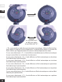
The numbers of preashes is variable from 1 time, 2 times, 3 times, 4 times, 5 times,
6 times, and 7 times. Press slave button
4
(Fig.1) 4 seconds to enter into preashes
setup menu “Cx ”.

6
EN
FR
ES
Press
UP or DOWN
button to adjust
preashes from 1 to 7
Press 4s
“C0” is automatic recognition mode. Use camera ash and release a test exposure.
The photocell detects the number of ashes the camera released and memorizes the
value automatically.
If you have selected «C1», the unit will autoash immediately when another ash is
activated in the same area.
If you have selected «C2» the unit will autoash on the second ash detected by the
photocell.
If you have selected «C3», the unit will autoash on the third ash detected by the
photocell.
If you have selected «C4», the unit will autoash on the fourth ash detected by the
photocell.
If you have selected «C5», the unit will autoash on the fth ash detected by the
photocell.
If you have selected «C6», the unit will autoash on the sixth ash detected by the
photocell.
If you have selected «C7», the unit will autoash on the seventh ash detected by
the photocell.

7
EN
FR
ES
The photocell is very sensitive but some experimentation with positioning may
be necessary to ensure a reliable trigger, particularly if the cell is not in the direct line
of sight of the triggering ash unit. Avoid directly illuminating the photocell from
a continuous light source (such as ceiling lights or windows) since this can prevent
correct operation. Very high ceilings can also aect the operation of the photocell.
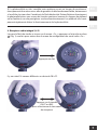
4. 2.4G Built-in Radio Receiver
When studio ash is at menu “Cx”, press slave button
4
(Fig.1) once to enter into
radio channel setup menu “Fx”.
Press once
There are totally 16 dierent channels for your choice from F0 to FF.
Press
UP or DOWN
button to select proper
receiver channel

8
EN
FR
ES
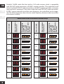
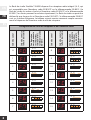
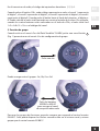
Starblitz® SHARK studio ash has built-in 2.4G radio receiver, which is compatible
with EX-816TC radio transmitter or EX-801C remote controller. (The studio ash itself
doesn’t include EX-816TC radio transmitter or EX-801C remote controller, customers
may purchase it separately.) Only when studio ash and EX-816TC radio transmitter/
EX-801C remote controller are at the same frequency, the studio ash can be trigge-
red. The following picture shows how to match frequency between radio transmitter
and receiver correctly.
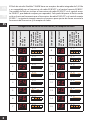
Channel code
Channel code on
Studio Flash
Corresponding
setup on EX-
816TC radio
transmitter
EX-801C remote
controller
0
F.0
O
1
N
2 3 4
1
F.1
O
1
N
2 3 4
2
F.2
O
1
N
2 3 4
3
F.3
O
1
N
2 3 4
4
F.4
O
1
N
2 3 4
5
F.5
O
1
N
2 3 4
6
F.6
O
1
N
2 3 4
7
F.7
O
1
N
2 3 4
Channel code
Channel code on
Studio Flash
Corresponding
setup on EX-
816TC radio
transmitter
EX-801C remote
controller
8
F.8
O
1
N
2 3 4
9
F.9
O
1
N
2 3 4
10
F.A
O
1
N
2 3 4
11
F.b
O
1
N
2 3 4
12
F.c
O
1
N
2 3 4
13
F.d
O
1
N
2 3 4
14
F.e
O
1
N
2 3 4
15
F.f
O
1
N
2 3 4
Radio Receiver and transmitter channel Setup

9
EN
FR
ES
On the radio transmitter, the code from left to right is 1,2,3,4.
When you push the button to “ON”, every code represents a value, channel 1 repre-
sents digit 1, channel 2 represents digit 2, channel 3 represents digit 4, channel 4
represents digit 8. When you push the button to “number side”, the digit is 0. You
can calculate the total value according to the key’s state. For example, when all the 4
buttons are set to “ON” side, the total value is 1+2+4+8=15. “15” is the channel code.
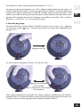
5. Group function
When Starblitz® SHARK studio ash at “Fx” menu, press slave button
4
(Fig.1) once to
switch to group setup menu “Gx”.
Press once
There are totally 4 groups for your choice from Ga, Gb, Gc to Gd.
Press
UP or DOWN
button to select proper
receiver channel
To use group function, you need to purchase separately a remote controller EX-801C.
Only when the studio ashes are at the same channel and same group as remote
controller EX-801C the studio ashes can be triggered.

10
EN
FR
ES
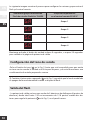
The following picture shows how to set the same groups between ash light and
remote controller.
Group number on
SHARK Studio Flash
Corresponding group
on remote controller EX-801C
G.A
Group 1
G.B
Group 2
G.C
Group 3
G.d
Group 4
Press the slave button 8 seconds, or wait 20 seconds to quit to output power page.
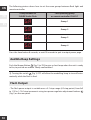
Audible Beep Settings
Push the Beeper Button
5
(Fig.1) to ‘ON’ to give a short beep when the unit is ready
to re, to provide an audible “Ready conrmation”.
Turning the switch
5
(Fig.1) OFF will allow the modelling lamp to turn o auto-
matically while the ash is red.
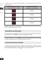
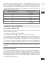
Flash Output
- The ash power output is variable over a 5 f-stops range (6 f-stop points) from full
to 1/32 in 1/10 f-stop increments using two power regulator adjustment buttons
1
(Fig.1) on the rear panel.

11
EN
FR
ES
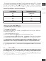
- The control has a minimum setting of 1.0 and a maximum setting of 6.0. Pressing
the regulator adjustment buttons
1
(Fig.1) will change the value by 0.1 f-stop (to
give you a total of 50 values. E.g. If the current value shown is 5.6 then to reduce the
power by 1 f-stop just reduce it to 4.6. The following table shows the whole decimal
numbers and equivalent fractional power ration:
Display power Fractional equivalent
6.0 1 (maximum)
5.0 1/2
4.0 1/4
3.0 1/8
2.0 1/16
1.0 1/32 (minimum)
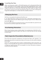
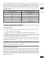
Changing the Flash Tube
1. Discharge the Flash Unit
The charge in the ash unit must be discharged before removing the ash tube.
To discharge the ash unit:
1-1. Make sure the ash unit is ON.
1-2. Push the «TEST» button
6
(Fig.1) on the rear panel of the ash.
1-3. Immediately turn o the power switch on the rear panel of the ash. Do not allow
more than 1/2 second between pressing the «TEST» button and the power switch.
1-4. Remove power cord from power source before removing the ashtube. It is re-
commended to wait at least 30 minutes before touching/removing the ash tube.
Use white cotton gloves or a clean cloth or glove to prevent ngers from touching
the ash tube.
2.Remove Old Flash Tube
First, remove the reector. Then, using white cotton gloves or a clean cloth, remove
the modeling lamp. You will need to remove the retention spring wrapped around
the top of the ash tube. With needle-nose pliers, unhook the retention spring loop.
Using white cotton gloves or a clean cloth, grip the base of the ash tube on each
side. Carefully pull the ash tube from the ash unit.

12
EN
FR
ES
3. Install New Flash Tube
Make sure the power switch is o and the power cord is disconnected from the
source. Locate the two ash tube pin sockets above the modeling lamp socket. Using
white cotton gloves or a clean cloth, push the pins of the ash tube into the sockets
using rm, even pressure at the base of the ash tube. With needle-nose pliers, hook
the retention spring over the hook above the ash tube. Re-insert the modeling lamp
using white cotton gloves or a clean cloth. Re-install the reector.
Changing the Fuse
A 4A fuse is mounted at the bottom of the ash unit.
1. Turn o the ash light, and disconnect the power supply before changing the fuse.
Never replace with a fuse of a dierent type or rating. A spare 4A fuse is tted in the
fuse holder
9
(Fig.1).
2.Use a small screwdriver to release fuse cover, remove the older fuse, place the new
fuse in the slot, and then replace the fuse holder.
Overheating Protection
After a long shooting session at high output, the recycling time of the ash will in-
crease automatically until the ash cools down to a safe level and will start working
normally again.
Flash Capacitor Preventative Maintenance
One of the most important components of an electronic ash is the capacitors. Fol-
lowing the preventative maintenance below will increase the life and the reliability
of your ash.
If the unit is left unused for a few months or predominantly used at low power set-
tings, it is recommended that the power be increased to maximum and the unit left
switched on (modeling lamp OFF) occasionally for at least 30 minutes to help pre-
serve the life of the capacitors.

13
EN
FR
ES
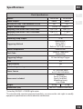
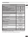
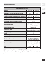
Specications
Flash Specications
Models SHARK200 SHARK400
Power Output 200W 400W
GN (2m, ISO 100) 1/60 Reector SF-610 50 70
Output Control range Full to 1/32 Stepless
Recycling Time to Full 220V-240V/50Hz 0,5~1,8s 0,8~2,3 s
Recycling Time to Full 110V-120V/60Hz 0,8~2,1s 1~3,0s
Flash Duration 1/800
e
~ 1/1200
e
Modelling Lamp Output 75W
Triggering Method
Slave Sensor /
Sync Cable /
Test Button/
Built-in 2.4G radio receiver
Colour Temperature 5600K±200°
Flash Tube
“plug-in” Tube (user
replaceable)
Triggering Voltage 5V Low Voltage Trigger
Fuse 4A
Digital display Yes
Overheating warning Yes
Power Source
AC 190-240V 50Hz
or AC 100-130V 60Hz
Accessories Included
Reector,
Power Cord(4m),
Synch Cord(4m),
Modelling Lamp,
User Guide
Weight 0,9 kg 1,1 kg
Dimensions (cm) 20x12x12 (without reector)
*Tested by SEKONIC L-758DR Light meter
*To coincide with constant improved products, we reserve the sole right to modify
equipment specication without advance notication.


1
EN
FR
ES
Torche monobloc
STARBLITZ® SHARK200/SHARK400
Mode d’emploi
Nous vous remercions d’avoir choisi le Starblitz® SHARK. Veuillez lire ces instructions
attentivement et les conserver pour référence future.
Le Starblitz® SHARK est une puissante torche monobloc autonome alimentée par
courant alternatif.
Ce ash vous ore souplesse de positionnement et facilité d’utilisation.
Veuillez vous assurer de bien connaître le fonctionnement et les fonctionnalités de
votre nouveau ash avant de l’utiliser.
Sommaire
Notes de sécurité .................................................................................................... 2
Contenu du carton .................................................................................................. 2
Préparation de votre ash avant utilisation ......................................................... 3
Connexion à l’alimentation .................................................................................... 3
Support pour éclairage avec support d’ombrelle ................................................ 5
Fonctionnement de la lampe de mise au point .................................................... 5
Déclenchement du ash ......................................................................................... 5
Paramètres de bip audio ...................................................................................... 10
Puissance de sortie du ash ................................................................................. 10
Changement du tube du ash ............................................................................. 11
Changement du fusible ........................................................................................ 12
Protection contre les surchaues ........................................................................ 12
Entretien préventif des condensateurs du ash ................................................ 12
Caractéristiques .................................................................................................... 13

2
EN
FR
ES
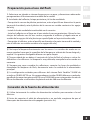
Notes de sécurité
Ne pas utiliser le ash dans un environnement où de l’humidité ou une vapeur
inammable est susceptible d’entrer en contact avec l’unité.
Il existe un risque d’incendie si des matériaux inammables sont placés à proxi-
mité immédiate du tube du ash ou de la lampe de mise au point lorsque l’unité est
en fonctionnement.
Ne pas occulter les aérations pendant son utilisation.
Toujours éteindre et débrancher l’alimentation secteur avant de changer le fu-
sible, la lampe de mise au point ou le tube du ash.
Éviter de placer les câbles là où des gens pourraient trébucher dessus. Protéger
des objets lourds, tranchants ou chauds, qui pourraient provoquer des dégâts. Rem-
placer immédiatement les câbles endommagés.
Ne jamais utiliser une unité présentant des caches, des moulures, des tubes de
ash ou une lampe de mise au point endommagés. Si l’unité tombe ou est endom-
magée de quelque façon, toujours la faire contrôler avant de l’utiliser.
Utiliser une brosse souante ou une lingette propre pour retirer la poussière et
l’humidité de la lampe de mise au point et du tube du ash. N’utiliser aucun liquide
sur la lampe de mise au point et le tube du ash.
Éteindre l’unité et débrancher le cordon d’alimentation si le ash n’est pas utilisé
pendant un moment.
Ne pas utiliser plus de 8fois par minute.
Nous recommandons de charger le ash pendant 2heures avant son utilisation
initiale et après une période d’inactivité prolongée (2 à 3semaines).
En raison des circuits à haute tension à l’intérieur de l’unité, ne pas tenter de dé-
monter le ash vous-même.
Tenir hors de portée des enfants.
Contenu du pack
Contenu du carton
Flash de 110V-120V ou 220V-240V avec tube de ash
Lampe de mise au point de 75W
Réecteur standard (avec ou sans réecteur standard)
Cache de protection
Câble d’alimentation
Câble de synchronisation de 4,5V
Guide de l’utilisateur

3
EN
FR
ES
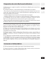
Préparation de votre ash avant utilisation
1. Sélectionnez un support au poids et aux dimensions adaptés pour assurer la sta-
bilité de l’unité.
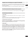
2. Installez le réecteur / cache de protection et la lampe de mise au point
- Pour retirer le cache de protection en plastique, poussez le bouton de verrou vers
l’arrière de l’unité et faites tourner le cache de protection en plastique dans le sens
inverse des aiguilles d’une montre.
- Installez la lampe de mise au point en l’insérant dans la connexion.
- Installez le réecteur là où se trouvait le cache de protection. Alignez les trois ches
sur le réecteur avec les trois orices, enclenchez le réecteur et faites-le tourner
dans le sens des aiguilles d’une montre jusqu’à ce qu’il se mette en place.
- Pour le retirer, poussez le bouton de verrou vers l’arrière de l’unité et faites tourner
le réecteur dans le sens inverse des aiguilles d’une montre.
Ne touchez pas la lampe à mains nues. Des résidus d’huile sur les doigts peuvent
amener la surface de la lampe à chauer de façon irrégulière et à exploser. Utilisez
des gants en coton blanc ou un chion propre.
Prenez soin de ne pas endommager le tube du ash lors de la xation ou du retrait
des réecteurs ou des boîtes à lumière. Le tube du ash est très délicat, évitez toute
manipulation non nécessaire.
Éteignez toujours l’unité et débranchez l’alimentation secteur avant de xer et
changer les réecteurs, d’insérer la lampe de mise au point ou de remplacer le tube
du ash.
La conguration standard de boîte à lumière pour ash de studio Starblitz® SHARK
est SB-030 50*70cm. Nous ne recommandons pas l’installation d’une boîte à lumière
carrée SB-030 supérieure à 60*90cm ou d’une boîte à lumière octogonale SB-038
d’un diamètre supérieur à 80 cm ou d’un bol beauté d’un diamètre supérieur à
460mm.
Connexion à l’alimentation
Utilisez uniquement les câbles fournis pour le branchement secteur.
Avant de brancher le cordon d’alimentation dans la prise murale, assurez-vous
que l’interrupteur est en position arrêt (position «0»).

4
EN
FR
ES
2
3
4
5
6
7
8
9
10
11
12
1
Fig.1
1
Régulateur de la puissance du ash
2
Lampe de mise au point activée/désactivée
3
Photocellule (esclave)
4
Touche d’activation/désactivation de la photocellule (esclave)
5
Touche d’activation/désactivation du bip du ash
6
Touche TEST
7
A chage LED
8
Entrée du câble de synchronisation
9
Fusible
10
Porte-ombrelle
11
Interrupteur principal
12
Entrée du câble d’alimentation
La page est en cours de chargement...
La page est en cours de chargement...
La page est en cours de chargement...
La page est en cours de chargement...
La page est en cours de chargement...
La page est en cours de chargement...
La page est en cours de chargement...
La page est en cours de chargement...
La page est en cours de chargement...
La page est en cours de chargement...
La page est en cours de chargement...
La page est en cours de chargement...
La page est en cours de chargement...
La page est en cours de chargement...
La page est en cours de chargement...
La page est en cours de chargement...
La page est en cours de chargement...
La page est en cours de chargement...
La page est en cours de chargement...
La page est en cours de chargement...
La page est en cours de chargement...
La page est en cours de chargement...
La page est en cours de chargement...
La page est en cours de chargement...
-
 1
1
-
 2
2
-
 3
3
-
 4
4
-
 5
5
-
 6
6
-
 7
7
-
 8
8
-
 9
9
-
 10
10
-
 11
11
-
 12
12
-
 13
13
-
 14
14
-
 15
15
-
 16
16
-
 17
17
-
 18
18
-
 19
19
-
 20
20
-
 21
21
-
 22
22
-
 23
23
-
 24
24
-
 25
25
-
 26
26
-
 27
27
-
 28
28
-
 29
29
-
 30
30
-
 31
31
-
 32
32
-
 33
33
-
 34
34
-
 35
35
-
 36
36
-
 37
37
-
 38
38
-
 39
39
-
 40
40
-
 41
41
-
 42
42
-
 43
43
-
 44
44


Starblitz Kit studio 2x400W Le manuel du propriétaire
- Catégorie
- Accessoires pour appareil photo
- Taper
- Le manuel du propriétaire
- Ce manuel convient également à
dans d''autres langues
Autres documents
-
Broncolor Impact 21 / 41 Le manuel du propriétaire
-
Elinchrom D-Lite it 2 & 4 Manuel utilisateur
-
-
Elinchrom D-Lite RX ONE Manuel utilisateur
-
-
-
-
-
 Elinca Digital RX Manuel utilisateur
-
