Faber GLASIS36SS600B Guide d'installation
- Catégorie
- Hottes
- Taper
- Guide d'installation

GLASIS36SS600-B
Installation Instructions
Use and Care Information
Instructions d'installation
Utilisez et d'entretien
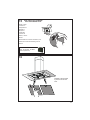
GLASSY IS 36"

2
READ AND SAVE THESE INSTRUCTIONS BEFORE YOU START
INSTALLING THIS RANGEHOOD
WARNING: - TO REDUCE THE RISK OF A RANGE TOP GREASE FIRE:
a) Never leave surface units unattended at high settings. Boilovers cause smoking and
greasy spillovers that may ignite. Heat oils slowly on low or medium setting.
A KV@XRSTQMGNNC.-VGDMBNNJHMF@SGHFGGD@SNQVGDMl@LADHMFENNCHD"QDODR
Suzette, Cherries Jubilee, Peppercorn Beef Flambé).
c) Clean ventilating fans frequently. Grease should not be allowed to accumulate on fan
NQkKSDQ
d) Use proper pan size. Always use cookware appropriate for the size of the surface element.
WARNING: - TO REDUCE THE RISK OF INJURY TO PERSONS IN THE EVENT OF A
RANGE TOP GREASE FIRE, OBSERVE THE FOLLOWING*:
@2,.3'$1%+ ,$2VHSG@BKNRDkSSHMFKHCBNNJHDRGDDSNQLDS@KSQ@XSGDMSTQMNEESGDATQMDQ
!$" 1$%4+3./1$5$-3!41-2(ESGDl@LDRCNMNSFNNTSHLLDCH@SDKX$5 "4 3$
AND CALL THE FIRE DEPARTMENT.
b) NEVER PICK UP A FLAMING PAN - You may be burned.
c) DO NOT USE WATER, including wet dishcloths or towels - a violent steam explosion will
result.
d) Use an extinguisher ONLY if:
1. You know you have a Class ABC extinguisher, and you already know how to operate it.
3GDkQDHRRL@KK@MCBNMS@HMDCHMSGD@QD@VGDQDHSRS@QSDC
3GDkQDCDO@QSLDMSHRADHMFB@KKDC
8NTB@MkFGSSGDkQDVHSGXNTQA@BJSN@MDWHS
* Based on "Kitchen Firesafety Tips" published by NFPA
WARNING - TO REDUCE THE RISK OF FIRE OR ELECTRIC SHOCK, do not use this
fan with any solid-state speed control device.
WARNING - TO REDUCE THE RISK OF FIRE, ELECTRICAL SHOCK, OR INJURY TO
PERSONS, OBSERVE THE FOLLOWING:
1. Use this unit only in the manner intended by the manufacturer. If you have any
questions, contact the manufacturer.
2. Before servicing or cleaning unit, switch power off at service panel and lock the
service disconnecting means to prevent power from being switched on acciden-
tally. When the service disconnecting means cannot be locked, securely fasten a
prominent warning device, such as a tag, to the service panel.
CAUTION: For General Ventilating Use Only. Do Not Use To Exhaust Hazardous or
Explosive Materials and Vapors.
WARNING - TO REDUCE THE RISK OF FIRE, ELECTRICAL SHOCK, OR INJURY TO
PERSONS, OBSERVE THE FOLLOWING:
1. (MRS@KK@SHNM6NQJ MC$KDBSQHB@K6HQHMF,TRS!D#NMD!X0T@KHkDC/DQRNMR(M BBNQ-
dance With All Applicable Codes And Standards, Including Fire-Rated Construction.
2. 2TEkBHDMS@HQHRMDDCDCENQOQNODQBNLATRSHNM@MCDWG@TRSHMFNEF@RDRSGQNTFG
SGDlTDBGHLMDXNEETDKATQMHMFDPTHOLDMSSNOQDUDMSA@BJCQ@ESHMF%NKKNVSGD
heating equipment manufacturer's guideline and safety standards such as those
OTAKHRGDCAXSGD-@SHNM@K%HQD/QNSDBSHNM RRNBH@SHNM-%/ @MCSGD LDQHB@M
2NBHDSXENQ'D@SHMF1DEQHFDQ@SHNM@MC HQ"NMCHSHNMHMF$MFHMDDQR 2'1 $@MC
the local code authorities.

3
3. When cutting or drilling into wall or ceiling, do not damage electrical wiring and
other hidden utilities.
4. Ducted fans must always be vented to the outdoors.
ALL WALL AND FLOOR OPENINGS WHERE THE RANGEHOOD IS INSTALLED MUST
BE SEALED.
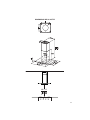
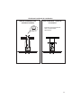
This rangehood requires at least 24" of clearance between the bottom of the rangehood
and the cooking surface or countertop. This hood has been approved by UL at this distance
from the cooktop. Overhead cabinets on both sides of this unit must be a minimum of 18" above
the cooking surface or countertop.
Consult the cooktop or range installation instructions given by the manufacturer before making
any cutouts. MOBILE HOME INSTALLATION The installation of this rangehood must conform
to the Manufactured Home Construction and Safety Standards, Title 24 CFR, Part 3280 (formerly
Federal Standard for Mobile Home Construction and Safety, Title 24, HUD, Part 280).
• Venting system MUST terminate outside the home.
• DO NOT terminate the ductwork in an attic or other enclosed space.
• DO NOT use 4" laundry-type wall caps.
• Flexible-type ductwork is not recommended.
• DO NOTNARSQTBSSGDkNVNEBNLATRSHNM@MCUDMSHK@SHNM@HQ
q%@HKTQDSNENKKNVUDMSHMFQDPTHQDLDMSRL@XQDRTKSHM@jQD
WARNING
Cold Weather installations
M@CCHSHNM@KA@BJCQ@ESC@LODQRGNTKCADHMRS@KKDCSNLHMHLHYDA@BJV@QCBNKC@HQkNV@MC@
nonmetallic thermal break should be installed to minimize conduction of outside temperatures as
part of the vent system. The damper should be on the cold air side of the thermal break. The break
should be as close as possible to where the vent system enters the heated portion of the house.
VENTING REQUIREMENTS
Determine which venting method is best for your application. Ductwork can extend either through the
wall or the roof.
3GDKDMFSGNESGDCTBSVNQJ@MCSGDMTLADQNEDKANVRRGNTKCADJDOSSN@LHMHLTLSNOQNUHCDDEjBHDMS
performance. The size of the ductwork should be uniform. Do not install two elbows together. Use
CTBSS@ODSNRD@K@KKINHMSRHMSGDCTBSVNQJRXRSDL4RDB@TKJHMFSNRD@KDWSDQHNQV@KKNQkNNQNODMHMF
around the cap.
Flexible ductwork is not recommended. Flexible ductwork creates back pressure and air turbulence
that greatly reduces performance.
,@JDRTQDSGDQDHROQNODQBKD@Q@MBDVHSGHMSGDV@KKNQkNNQENQDWG@TRSCTBSADENQDL@JHMFBTSNTSR
Do not cut a joist or stud unless absolutely necessary. If a joist or stud must be cut, then a supporting
frame must be constructed.
WARNING - To Reduce The Risk Of Fire, Use Only Metal Ductwork.
" 43(.-3NQDCTBDQHRJNEkQD@MCSNOQNODQKXDWG@TRS@HQADRTQDSNCTBS@HQNTSRHCDm#N
not vent exhaust air into spaces within walls or ceilings or into attics, crawl spaces, or garages.

4
ELECTRICAL REQUIREMENTS
A 120 volt, 60 Hz AC-only electrical supply is required on a separate 15 amp fused circuit. A time-delay
fuse or circuit breaker is recommended. The fuse must be sized per local codes in accordance with
SGDDKDBSQHB@KQ@SHMFNESGHRTMHS@RRODBHjDCNMSGDRDQH@KQ@SHMFOK@SDKNB@SDCHMRHCDSGDTMHSMD@QSGDjDKC
wiring compartment.
ELECTRICAL INSTALLATION WITH WIRING BOX
THIS UNIT MUST BE CONNECTED WITH COPPER WIRE ONLY. Wire sizes must conform to the
QDPTHQDLDMSRNESGD-@SHNM@K$KDBSQHB@K"NCD -2(-%/ K@SDRSDCHSHNM@MC@KKKNB@KBNCDR@MC
ordinances. Wire size and connections must conform with the rating of the appliance. Copies of the
standard listed above may be obtained from:
National Fire Protection Association
Batterymarch Park
Quincy, Massachusetts 02269
This appliance should be connected directly to the fused disconnect (or circuit breaker) through
kDWHAKD@QLNQDCNQMNMLDS@KKHBRGD@SGDCBNOODQB@AKD KKNVRNLDRK@BJHMSGDB@AKDRNSGD
@OOKH@MBDB@MADLNUDCHERDQUHBHMFHRDUDQMDBDRR@QX 4++HRSDCŭBNMCTHSBNMMDBSNQLTRS
be provided at each end of the power supply cable (at the appliance and at the junction box).
6GDML@JHMFSGDDKDBSQHB@KBNMMDBSHNMBTS@ŭGNKDHMSGDV@KK GNKDBTSSGQNTFGVNNC
must be sanded until smooth. A hole through metal must have a grommet.
• Electrical ground is required on this rangehood.
• If cold water pipe is interrupted by plastic, nonmetallic gaskets or other materials, DO
NOT use for grounding.
• DO NOT ground to a gas pipe.
• DO NOT have a fuse in the neutral or grounding circuit. A fuse in the neutral or
grounding circuit could result in electrical shock.
q"GDBJVHSG@PT@KHjDCDKDBSQHBH@MHEXNT@QDHMCNTAS@RSNVGDSGDQSGDQ@MFDGNNCHR
properly grounded.
q%@HKTQDSNENKKNVDKDBSQHB@KQDPTHQDLDMSRL@XQDRTKSHM@jQD
WARNING

5
RANGEHOOD DIMENSIONS
Min. 24"

6
10
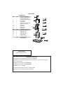
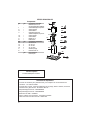
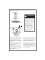
MAIN PARTS
Available Accessories
+LJK&HLOLQJ.LWWKDWUHSODFHVWKHORZHUÀXHVNX+,*+
'XFWOHVV.LW,QFOXGHV'XFWOHVV'LYHUWHU&KDUFRDO)LOWHUV/RZHUFKLPQH\ZLWKYHQW
JUDWHVVNX'8&7
0DNH8S$LU'DPSHU.LW08'$03(5
0DNH8S$LU'DPSHU.LW08'$03(5
&)05HGXFHU.LW&)05('
$FWLYDWHG&KDUFRDO)LOWHU$FFHVVRU\VNX),/7(5
- Wireless 5HPRWH&RQWURO$FFHVVRU\5(0&75/
Parts needed
5RXQG0HWDOGXFWZRUN
Components
Ref. Qty. Product Components
1 1 Hood Body, complete with: Con-
trols, Light, Filters, Blower.
2 1 Telescopic Chimney comprising:
2.1 1 Upper Section
2.2 1 Lower Section
7.1 1 Telescopic frame complete with
extractor, consisting of:
7.1a 1 Upper frame
7.1b 1 Lower frame
10 1 Damper ø 5 7/8"
24 1 Junction Box
Ref. Qty. Installation Components
12f 2 Screws 3/16" x 9/16"
12c 2 Screws 1/8" x 1/4"
12e 4 Screws 1/8" x 3/8"
12q 4 Screws 1/4" x 9/16"
21 1 Drilling template
22 4 1/4" int. dia washers
Qty. Documentation
1 Instruction Manual
1
2.2
2.1
21
7.1
12q
22
12c
12e
12f
24
7.1a
7.1b

7
Choose your ducting method
Non Ducted - Recirculation OptionDucted Venting Options Installation
5HTXLUHV'XFWOHVV$FFHVVRU\.LW
SXUFKDVHGVHSDUDWHO\
6 "

8
1
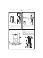
3XWDWKLFNSURWHFWLYHFRYHULQJRYHUFRRNWRS
VHWLQ UDQJH RU FRXQWHUWRS WR SURWHFW IURP
GDPDJHRUGLUW
'HWHUPLQHDQGFOHDUO\PDUNZLWKDSHQFLORQWKH
FHLOLQJZKHUHWKHUDQJHKRRGZLOOEHLQVWDOOHG
$ WHPSODWH IRU PRXQWLQJ WKH VXSSRUW LV
VXSSOLHG LQ WKH FDUWRQ ZLWK WKH VXSSRUW 8VH
WKLVWHPSODWHWRPDUNKROHVIRU
VXSSRUWRQWKHFHLOLQJ
'HWHUPLQH DQG PDNH QHFHVVDU\FXWV IRU WKH
GXFWZRUN7KHGXFWRSHQLQJLVVKRZQRQWKH
PRXQWLQJWHPSODWH,QVWDOO
GXFWZRUNEHIRUHPRXQWLQJWKHKRRG
'HWHUPLQH WKH SURSHU ORFDWLRQ IRU WKH 3RZHU
6XSSO\ &DEOH DV LQGLFDWHG RQ WKH WHPSODWH
8VH D 'ULOO %LW WR PDNH WKLV KROH 5XQ
WKH3RZHU6XSSO\&DEOH8VHFDXONLQJWRVHDO
DURXQGWKHKROH
$ NQRFNRXW IRU WKUHDGLQJ WKURXJK WKH 3RZHU
6XSSO\ IURP WKH FHLOLQJ LV ORFDWHG RQ WKH WRS
RIWKHIUDPH'RQRWFRQQHFWWKH3RZHU&DEOH
WRWKH:LULQJ%R[RUSRZHUXSWKHKRRGDWWKLV
WLPH5XQHQRXJKSRZHUFDEOHIURPWKHFHLOLQJ
WRUHDFKWKHZLULQJER[RQWKHKRRG
Ø 10 mm
x4
21
6
4
21
6
´
´
1 1/4"
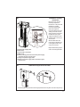
'RQRWPDNHDQ\FXWRXWVXQWLO\RXKDYHGHFLGHGZKHWKHUWKLVLQVWDOODWLRQZLOOEHGXFWHGRU
QRQGXFWDQGWKHQSODQDFFRUGLQJO\
DUE TO THE SIZE AND
WEIGHT OF THIS RANGE-
HOOD, THE SUPPORT MUST
BE FIRMLY ATTACHED TO
THE CEILING. For plaster or
sheet rock ceiling, the support
must be attached to the joists.
If this is not possible, a support
structure must be built behind
the plaster or sheet rock. The
manufacturer assumes no re-
sponsibility forinjury or damage
caused by improper installa-
tions.
WARNING
!

9
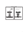
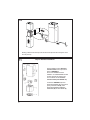
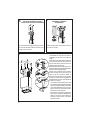
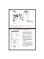
Chimney Flues Must Be Removed Before Installing the Hood
2
3
4
Loosen the two screws fastening the lower chimney
and remove this from the lower frame.
If you need to adjust the height of the frame,
proceed as follows:
• Unfasten the metric screws joining the two
columns, located at the sides of the frame
(1,2,3,4,5,6).
• Adjust the frame to the height required, then
UH¿WDOOWKHVFUHZVUHPRYHGDVDERYH
Loosen the two screws fastening the upper chimney
and remove this from the upper frame.
1
4
MIN
740
mm
MAX
940
mm
2
3
5
6

10
5
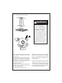
After the regulation for height adjustment, insert
the upper chimney stack from above, and leave it
running free on the frame.
Upper Flue Must Be In Place
Before Proceeding
6
Install Damper that is included with the Hood before
connecting to the ductwork.
Only for Ducted Venting
Installation
7
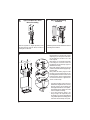
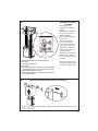
Now take either your woods screws or bolts
depending on your set-up and screw all four
into the pilot holes and leave 1/4" of the
heads exposed.
Next install a UL or CSA listed strain relief
in the wiring box so that the screws can
be tightened after the chimney support is
attached to the ceiling.
1RZ OLIW WKHFKLPQH\ VXSSRUWLQWR LWV ¿QDO
position and feed the electrical supply through
the strain relief.
Next position the chimney support so that
the large end of the keyhole slots are over
the ceiling attachment screws or bolts. Then
push the chimney support so that the bolts
are in the neck of the slots. Tighten all four
screws or bolts securely.
• The frame mountings must be secure to
withstand the weight of the hood and any
stresses caused by the occasional side
thrust applied to the device. On completion,
check that the base is stable, even if the
frame is subjected to bending.
• In all cases where the ceiling is not
strong enough at the suspension point,
the installer must provide strengthening
using suitable plates and backing pieces
anchored to the structurally sound parts.

11
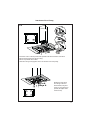
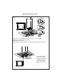
Installation of wiring
connection
Remove the cover from the
¿HOGZLULQJFRPSDUWPHQW
DO NOT turn on the power until
installation is complete!
Connect the Power Supply
Cable to the rangehood.
Connect the Green (Green and
Yellow) ground wire under the
Green grounding screw. Attach
the White lead of the power
supply to the White lead of the
rangehood with a twist-on type
wire connector.
Attach the Black lead of the
power supply to the Black lead
of the rangehood with a twist-
on type wire connector.
5HSODFHWKH¿HOGZLULQJFRPSDUW-
PHQWFRYHUDQGWKHJUHDVH¿OWHUV
A. Home power supply cable
B. Black wires
C. UL listed wire connectors
D. White wires
E. Green (or bare) ground wire from home power supply
connected to green ground screw
F. Range hood power supply cable
G. Range hood power supply cable connected to green
ground screw
5HPRYH WKH FRYHU IURP WKH ÀHOG ZLULQJ FRPSDUWPHQW
&RQQHFWWKH3RZHU6XSSO\&DEOHWRWKHUDQJHKRRG
&RQQHFWWKH*UHHQ*UHHQDQG<HOORZJURXQGZLUHXQGHUWKH
ZLUH FRQQHFWRU $WWDFK WKH %ODFN OHDG RI WKH SRZHU VXSSO\
WRWKH%ODFNOHDGRIWKHUDQJHKRRGZLWKDWZLVWRQW\SHZLUH
7KH 833(5 &+,01(<
&29(5
XVHWKH833(5
&+,01(< &29(5 VXSSOLHG
DWWDFKWKH833(5&+,01(<
&29(5
0DNHVXUHWRVHDODOOMRLQWVZLWK
7KH /2:(5 &+,01(<
&29(5
,QVWDOOWKH/2:(5&+,01(<
&29(5E\VOLGLQJLWXSRYHU
WKH VXSSRUW DQG WKH 833(5
&+,01(<&29(5
)RUGXFWOHVVLQVWDOODWLRQVOLQHXSWKH'8&7/(66',9(57(5
(;7(16,216+25,=217$/
LQWKH/2:(5&+,01(<&29(5
A. Home power supply cable
%%ODFNZLUHV
&8/OLVWHGZLUHFRQQHFWRUV
& + ,0 1( < & 29 (5
SODFH WKH '8&7/(66
H[KDXVWRSHQLQJRIWKH($6<
&8%( )LWWKH'8&7/(66
',9(57(5 (;7(16,216
+25,=217$/
8
9
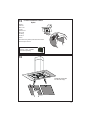
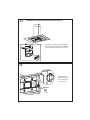
3RVLWLRQWKHXSSHUFKLPQH\VHFWLRQDQG¿[WKHXSSHUSDUWWRWKHIUDPHXVLQJWKHVFUHZVUHPRYHGSUHYLRXVO\
Attachment of Upper and Lower Flues

12
11
6LPLODUO\SRVLWLRQWKHORZHUFKLPQH\VHFWLRQDQG¿[WKHORZHUSDUWWRWKHIUDPHXVLQJWKHVFUHZV
removed previously.
10
Only For Ductless Installations
5HPRYH WKH FRYHU IURP WKH ÀHOG ZLULQJ FRPSDUWPHQW
&RQQHFWWKH3RZHU6XSSO\&DEOHWRWKHUDQJHKRRG
&RQQHFWWKH*UHHQ*UHHQDQG<HOORZJURXQGZLUHXQGHUWKH
ZLUH FRQQHFWRU $WWDFK WKH %ODFN OHDG RI WKH SRZHU VXSSO\
WRWKH%ODFNOHDGRIWKHUDQJHKRRG ZLWK DWZLVWRQW\SHZLUH
7KH 833(5 &+,01(<
&29(5
XVHWKH833(5
&+,01(< &29(5 VXSSOLHG
DWWDFKWKH833(5&+,01(<
&29(5
0DNHVXUHWRVHDODOOMRLQWVZLWK
7KH /2:(5 &+,01(<
&29(5
,QVWDOOWKH/2:(5&+,01(<
&29(5E\VOLGLQJLWXSRYHU
WKH VXSSRUW DQG WKH833(5
&+,01(<&29(5
)RUGXFWOHVVLQVWDOODWLRQVOLQHXSWKH'8&7/(66',9(57(5
(;7(16,216+25,=217$/
LQWKH/2:(5&+,01(<&29(5
%%ODFNZLUHV
&8/OLVWHGZLUHFRQQHFWRUV
Ductless installations require
Ductless Conversion
whose components are
. Do
M
) for ductless
The LOWER
& + , 0 1 (< & 2 9 ( 5 (B
should be
discarded and replaced by
the new one with holes from
Ductless Conversion Kit
FIGURE
SODFH WKH '8&7/(66
over the
H[KDXVWRSHQLQJRIWKH($6<
&8%( )LWWKH'8&7/(66
',9(57(5 (;7(16,216
+25,=217$/ into the
FIGURE 12
Ductless installations require a Ductless
Conversion Kit whose components are
pictured in FIGURE 12.
Do not use the DAMPER for ductless
installations. The LOWER CHIMNEY COVER
should be discarded and replaced by the
new one with holes from the Ductless
Conversion Kit (D in FIGURE 12).
As indicated in FIGURE 12, place the
DUCTLESS DIVERTER (A) over the exhaust
opening of the EASY CUBE (E). Fit the
DUCTLESS DIVERTER EXTENSIONS
HORIZONTAL (B) into the DIVERTER (A).

13
12
Screw the 2 screws 12f half way into the holes provided in the sides of the bottom of the frame.
5HPRYHWKHJUHDVH¿OWHUVIURPWKHKRRGFDQRS\
5HPRYHDQ\DFWLYDWHGFKDUFRDO¿OWHUV
Lift the hood canopy and engage the screws 12f in the slots as far as they will go.
12q x 4
22 x 4
:RUNLQJIURPEHORZ¿[WKH
hood canopy to the frame
where indicated, using the 4
screws 12q and 4 washers 22
provided, then tighten all the
screws securely.
12f
12f
1
2
3
Attachment of Hood Canopy

14
13
&RQQHFWWKHFRQWUROFRQQHFWRU&PG
3ODFHWKHFRQQHFWRUVLQWKHMXQFWLRQER[DQG
FORVHLWXVLQJWKHVFUHZVSURYLGHG
14
12c x 2
)L[WKHMXQFWLRQER[
WRWKHKRRGERG\
XVLQJWKHVFUHZV
FSURYLGHG
H
Make the Internal Electrical Connection

15
15
For Non-Ducted Recirculation
Option
5HTXLUHG$FWLYDWHG&KDUFRDO)LOWHU
$FFHVVRU\VNX),/7(5
SXUFKDVHGVHSDUDWHO\
$WWDFKD
charcoal
¿OWHULQWKH
correct
SRVLWLRQDQG
EORFNLWE\
WKH¿[LQJ
KRRNVDV
shown.
8QORFNWKH¿[LQJKRRNVWRZDUGVWKHEDFNRIWKH
LQVHUWKRRGWRUHPRYH
5HLQVWDOOWKHJUHDVH¿OWHUV
from the hood canopy.
16

16
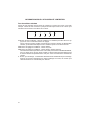
USE AND CARE INFORMATION
T1)DQ2II%XWWRQ7XUQWKHEORZHU2II7KHIDQFDQEHRSHUDWHGE\SUHVVLQJDQ\RIWKHIDQVHWWLQJ
EXWWRQV
+ROGGRZQWKLVEXWWRQIRUVHFRQGVWRDFWLYDWH'HOD\2IIIXQFWLRQZKLFKZLOONHHSWKHIDQ2QIRU
PLQXWHVDQGDXWRPDWLFDOO\VKXW2II
T2)DQ6HWWLQJV%XWWRQV/RZ6SHHG
T3)DQ6HWWLQJV%XWWRQV0HGLXP6SHHG
T4)DQ6HWWLQJV%XWWRQV+LJK6SHHG,QWHQVLYH6SHHG
+ROGGRZQWKHEXWWRQIRUVHFRQGVWRDFWLYDWHWKH,17(16,9(63(('ZKLFKLVWLPHGWRUXQIRU
PLQXWHV$WWKHHQGRIWKLVWLPHLWZLOODXWRPDWLFDOO\UHWXUQWRWKHVSHHGVHWEHIRUH6XLWDEOHWRGHDO
ZLWKPD[LPXPOHYHOVRIFRRNLQJIXPHV
L /LJKW%XWWRQ2Q'LP2IIVZLWFKIRUWKHOLJKWV3UHVVWKH/,*+7EXWWRQWRWXUQWKHOLJKWRQDJDLQWR
VHWWKHOLJKWVWRGLPPHUDQGDJDLQWRWXUQRII
LT1 T2 T3 T4
For Best Results
6WDUW WKH UDQJHKRRG VHYHUDO PLQXWHV EHIRUH FRRNLQJ WR GHYHORS SURSHU DLUÀRZ$OORZ WKH
UDQJHKRRGWRRSHUDWHIRUVHYHUDOPLQXWHVDIWHUFRRNLQJLVFRPSOHWHWRFOHDUDOOVPRNHDQG
RGRUVIURPWKHNLWFKHQ

17
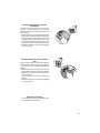
"KD@MHMFLDS@KFQD@RDkKSDQR
7KH¿OWHUVPXVWEHFOHDQHGHYHU\PRQWKVRIRSHUDWLRQRUPRUH
frequently for particularly heavy usage, and can be washed in
a dishwasher.
• Remove the Filters one at a time, pushing them towards
the back of the unit and at the same time pulling downward.
• Wash the Filters without bending them, and leave them to
GU\FRPSOHWHO\EHIRUHUHSODFLQJ,IWKHVXUIDFHRIWKH¿OWHU
changes color as time goes by, this will have absolutely no
HIIHFWRQWKHHI¿FLHQF\RIWKH¿OWHULWVHOI
• Replace, taking care to ensure that the handle faces forwards.
Replacing Activated Charcoal Filter
7KH¿OWHULVQRWZDVKDEOHDQGFDQQRWEHUHJHQHUDWHGDQGPXVW
be replaced approximately every 4 months of operation, or more
frequently for particularly heavy usage.
• Remove the Filters one at a time, pushing them towards
the back of the unit and at the same time pulling downward.
• 5HPRYHWKHVDWXUDWHGFKDUFRDO¿OWHUE\UHOHDVLQJWKH¿[LQJ
hooks.
• )LWWKHQHZ¿OWHUDQGIDVWHQLWLQLWVFRUUHFWSRVLWLRQ
• Replace, taking care to ensure that the handle faces forwards.
Lighting Unit
• LED lights must be replaced by Faber factory authorized
service.

18
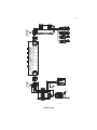
Wiring Diagram
Dolce, Corrado
17-Feb-2016
+B
5HY
'UDZLQJ1
'RQRWJHWTX RWDVIURPWKHGUDZLQJGRQRW EULQJPRGLILFDWLRQVZLWKRXWDXWKRUL]DWLRQRIWHFKLQFDO RIILFH
$FFRUGLQJW RWKHODZZHUHVHUYHWKHRZQRIWKHSUHVHQWGUDZLQJZLWKUHSURGXFWLRQSURKLELWLRQSDUWLDORUWRWDO
0RGLIE\
0RGLILFDWLRQGHVFULSWLRQ
'RFVWDWXV
:,5,1*',$*5$00961223</(',6
$SSURYHGGDWH
'HQRPLQDWLRQ
$SSURYHGE\
'RF7\SH
)HE
&UHDWLRQGDWH
'2/&(&255$'2
&UHDWHGE\
&RGH
%5:
*5<
5('
:+7
%/8
%/8
%5:
09
,17(51$/
%/2:(5
%/.
25*
25*
:+7
%/.
%/8
%/8
25*
ER[ZD\FRQQHFWRU
FRG
25*
%/.
:+7
%/8
%5:
*5<
:,5,1*
%2;
<*
5(':+7
%5:%/.
/,1(
9DF+]
61223<
&1
&1
%/.
*5<
/('
%/.
*5<
/('
%/.
*5<
/('
6(&
(/(&7 521,&
751 6) 250(5
/1
25*%/.YOW%/.
ER[ZD\FRQQHFWRU
FRG
25*
*5<UHG*5<
/('

19
January 4, 2016
FABER CONSUMER WARRANTY & SERVICE
All Faber products are warranted against any defect in materials or workmanship for the original purchaser
for a period of 1 year from the date of original purchase (requires proof of purchase). This warranty covers
labor and replacement parts. Faber, at its option, may repair or replace the product or components
necessary to restore the product to good working condition. To obtain warranty service, contact the dealer
from whom you purchased the range hood, or the local Faber distributor. If you cannot identify a local Faber
distributor, contact us at (508) 358-5353 for the name of a distributor in your area.
The following is not covered by Faber's warranty:
1. Service calls to correct the installation of your range hood, to instruct you how to use your range hood, to
replace or repair house fuses or to correct house wiring or plumbing.
2. Service calls to repair or replace range hood light bulbs, fuses or filters. Those consumable parts are
excluded from warranty coverage.
3. Repairs when your range hood is used for other than normal, single-family household use.
4. Damage resulting from accident, alteration, misuse, abuse, fire, flood, acts of God, improper installation,
installation not in accordance with electrical or plumbing codes or Faber documentation, or use of products
not approved by Faber.
5. Replacement parts or repair labor costs for units operated outside the United States or Canada, including
any non-UL or C-UL approved Faber range hoods.
6. Repairs to the hood resulting from unauthorized modifications made to the range hood.
7. Expenses for travel and transportation for product service in remote locations and pickup and delivery
charges. Faber range hoods should be serviced in the home.
THIS WARRANTY DOES NOT ALLOW RECOVERY OF INCIDENTAL OR CONSEQUENTIAL DAMAGES, INCLUDING, WITHOUT
LIMITATION, DIRECT, INDIRECT, INCIDENTAL, SPECIAL OR CONSEQUENTIAL DAMAGES, PERSONAL INJURY/WRONGFUL
DEATH OR LOST PROFITS FABER WARRANTY IS LIMITED TO THE ABOVE CONDITIONS AND TO THE WARRANTY PERIOD
SPECIFIED HEREIN AND IS EXCLUSIVE. EXCEPT AS EXPRESSLY SPECIFIED IN THIS AGREEMENT, FABER DISCLAIMS ALL
EXPRESS OR IMPLIED CONDITIONS, REPRESENTATIONS, AND WARRANTIES INCLUDING, WITHOUT LIMITATION, ANY
IMPLIED WARRANTIES OF MERCHANTABILITY OR FITNESS FOR A PARTICULAR PURPOSE
.
This warranty gives you specific legal rights that may vary from state to state.
Model#: ______________________________ Serial #: _____________________________

20
VEUILLEZ LIRE ET CONSERVER LA PRÉSENTE NOTICE AVANT DE
COMMENCER L'INSTALLATION DE LA HOTTE DE CUISINE
AVERTISSEMENT : POUR RÉDUIRE LE RISQUE D'UN FEU DE GRAISSE SUR LA TABLE DE
"4(22.-Ů
a) Ne laissez jamais sans surveillance les éléments de la surface de cuisson à température élevée.
Les bouillonnements excessifs peuvent provoquer de la fumée et les débordements de graisse
ODTUDMSRfDMl@LLDQ+fGTHKDCNHSģSQDBG@TEEĢDKDMSDLDMSĒTMDSDLOĢQ@STQDA@RRDNTLNXDMMD
b) Assurez-vous de toujours mettre en marche le ventilateur de la hotte lorsque vous cuisinez à
SDLOĢQ@STQDĢKDUĢDNTOQĢO@QDYTMLDSRl@LAĢODWBQģODR2TYDSSDBDQHRDRITAHKĢATEl@LAĢ
c) Nettoyez régulièrement les ventilateurs d'aspiration. Assurez-vous de ne pas laisser de la
FQ@HRRDRf@BBTLTKDQRTQKDUDMSHK@SDTQNTKDkKSQD
C4SHKHRDYSNTINTQRCDRONģKDRDSB@RRDQNKDRCDK@S@HKKD@OOQNOQHĢD4SHKHRDYSNTINTQRCDRTRSDMRHKDR
de cuisine de la taille adaptée à celle de l'élément chauffant.
5$13(22$,$-3Ů/.41/1Í5$-(1+$2!+$2241$2$-" 2#$%$4#$&1 (22$241+
3 !+$#$"4(22.-24(5$9+$21$".,, -# 3(.-224(5 -3$2Ů
a) ÉTOUFFEZ LES FLAMMES à l'aide d'un couvercle hermétique, d'une plaque à biscuits ou d'un
plateau métallique, puis éteignez le brûleur. FAITES ATTENTION AUX BRÛLURES. Si le feu ne
s'éteint pas immédiatement, QUITTEZ LES LIEUX ET APPELEZ LES POMPIERS.
b) NE PRENEZ JAMAIS UNE CASSEROLE EN FLAMME - Vous pourriez vous brûler.
c) N'UTILISEZ JAMAIS DE L'EAU, ni un linge à vaisselle ou un torchon mouillé, pour éteindre le
feu. Cela pourrait provoquer une violente explosion de vapeur.
C4SHKHRDYTMDWSHMBSDTQ4-(04$,$-3RHŮ
5NTRģSDRBDQS@HMPTfHKRf@FHSCfTMDWSHMBSDTQCDBK@RRD !"DSPTDUNTRBNMM@HRRDYAHDM
son mode d'emploi.
2. Le feu est de faible intensité et se limite à l'endroit où il a démarré.
3. Les pompiers ont déjà été appelés.
4MDUNHDCDRNQSHDRDSQNTUDCDQQHġQDUNTRODMC@MSPTDUNTRĢSDHFMDYKDRl@LLDR
#e@OQĠRKDFTHCDgŰ*HSBGDM%HQDR@EDSX3HORŰuOTAKHġO@QK@-%/ @TWÍS@SR4MHR
AVERTISSEMENT - POUR RÉDUIRE LE RISQUE D'INCENDIE OU DE CHOC ÉLECTRIQUE, n'utilisez
jamais ce ventilateur en association avec un dispositif de réglage de vitesse à semi-conducteurs.
AVERTISSEMENT - POUR RÉDUIRE LES RISQUES D'INCENDIE, DE CHOC ÉLECTRIQUE OU
#$!+$2241$".1/.1$++$1$2/$"3$9+$2(-2314"3(.-224(5 -3$2Ů
1. Utilisez cet appareil uniquement de la façon prévue par le fabricant. Pour toute question,
communiquez avec le fabricant.
2. Avant de procéder à l'entretien ou au nettoyage de l'appareil, coupez l'alimentation au
niveau du panneau électrique et verrouillez-le pour vous assurer que l'électricité n'est pas
rétablie accidentellement. S'il n'est pas possible de verrouiller le dispositif d'interruption de
Kf@KHLDMS@SHNM@EkBGDYCDE@ĞNMEDQLDDSAHDMUHRHAKDTM@UHRCDC@MFDQO@QDWDLOKDĒKf@HCD
d'une étiquette sur le panneau.
33$-3(.-Ů#DRSHMĢĒTMTR@FDCDUDMSHK@SHNMFĢMĢQ@KDTMHPTDLDMS-fTSHKHRDYO@RBDCHRONRHSHE
pour l'aspiration de vapeurs ou de matériaux dangereux ou explosifs.
AVERTISSEMENT - POUR RÉDUIRE LES RISQUES D'INCENDIE, DE CHOC ÉLECTRIQUE OU
#$!+$2241$".1/.1$++$1$2/$"3$9+$2(-2314"3(.-224(5 -3$2Ů
1. +fHMRS@KK@SHNMDSKDAQ@MBGDLDMSĢKDBSQHPTDCNHUDMSģSQDQĢ@KHRĢRO@QTMSDBGMHBHDMPT@KHkĢ
et conformément à tous les codes et normes en vigueur, incluant ceux concernant la con-
struction à l'épreuve du feu.
2. kMCDF@Q@MSHQTMDBNLATRSHNMDSTMDĢU@BT@SHNM@CĢPT@SDRCDRF@YO@QKDRBNMCTHSDR
de la cheminée des appareils à combustion, une bonne aération est nécessaire pour éviter
le refoulement. Respectez les lignes directrices fournies par le fabricant du matériel chauf-
fant, ainsi que les normes de sécurité comme celles publiées par la National Fire Protection
RRNBH@SHNM-%/ DSK@ LDQHB@M2NBHDSXENQ'D@SHMF1DEQHFDQ@SHNM@MC HQ"NMCHSHNMHMF
$MFHMDDQR 2'1 $@TWÍS@SR4MHR@HMRHPTDKDRBNCDRDMUHFTDTQC@MRUNSQDQĢFHNM
La page est en cours de chargement...
La page est en cours de chargement...
La page est en cours de chargement...
La page est en cours de chargement...
La page est en cours de chargement...
La page est en cours de chargement...
La page est en cours de chargement...
La page est en cours de chargement...
La page est en cours de chargement...
La page est en cours de chargement...
La page est en cours de chargement...
La page est en cours de chargement...
La page est en cours de chargement...
La page est en cours de chargement...
La page est en cours de chargement...
La page est en cours de chargement...
La page est en cours de chargement...
La page est en cours de chargement...
La page est en cours de chargement...
La page est en cours de chargement...
-
 1
1
-
 2
2
-
 3
3
-
 4
4
-
 5
5
-
 6
6
-
 7
7
-
 8
8
-
 9
9
-
 10
10
-
 11
11
-
 12
12
-
 13
13
-
 14
14
-
 15
15
-
 16
16
-
 17
17
-
 18
18
-
 19
19
-
 20
20
-
 21
21
-
 22
22
-
 23
23
-
 24
24
-
 25
25
-
 26
26
-
 27
27
-
 28
28
-
 29
29
-
 30
30
-
 31
31
-
 32
32
-
 33
33
-
 34
34
-
 35
35
-
 36
36
-
 37
37
-
 38
38
-
 39
39
-
 40
40


Faber GLASIS36SS600B Guide d'installation
- Catégorie
- Hottes
- Taper
- Guide d'installation
dans d''autres langues
Documents connexes
-
Faber LEVL36SS400 Guide d'installation
-
-
-
Faber CLAS30SS300B Guide d'installation
-
-
-
-
-
-
