WIKA TR33 Mode d'emploi
- Catégorie
- Thermomètres corporels numériques
- Taper
- Mode d'emploi

DE
EN
Operating instructions
Betriebsanleitung
Mode d’emploi
Manual de instrucciones
ES
FR
Miniature resistance thermometer, model TR33
Miniature resistance thermometer, model TR33
Miniatur-Widerstandsthermometer, Typ TR33
Sonde à résistance miniature, type TR33
Termorresistencia miniatura, modelo TR33
70018194

2
14073818.09 07/2018 EN/DE/FR/ES
WIKA operating instructions model TR33
DE
EN
FR
ES
Operating instructions model TR33 Page 3 - 32
Betriebsanleitung Typ TR33 Seite 33 - 62
Mode d'emploi type TR33 Page 63 - 92
Manual de instrucciones modelo TR33 Página 93 - 122
© 01/2014 WIKA Alexander Wiegand SE & Co. KG
All rights reserved. / Alle Rechte vorbehalten.
WIKA
®
is a registered trademark in various countries.
WIKA
®
ist eine geschützte Marke in verschiedenen Ländern.
Prior to starting any work, read the operating instructions!
Keep for later use!
Vor Beginn aller Arbeiten Betriebsanleitung lesen!
Zum späteren Gebrauch aufbewahren!
Lire le mode d‘emploi avant de commencer toute opération !
A conserver pour une utilisation ultérieure !
¡Leer el manual de instrucciones antes de comenzar cualquier trabajo!
¡Guardar el manual para una eventual consulta!

EN
WIKA operating instructions model TR33
14073818.09 07/2018 EN/DE/FR/ES
3
Contents
Contents
Declarations of conformity can be found online at www.wika.com.
1. General information 4
2. Safety 6
3. Specications 10
4. Design and function 13
5. Transport, packaging and storage 16
6. Commissioning, operation 17
7. Conguration 24
8. CongurationsoftwareWIKAsoft-TT 25
9. Connecting PU-548 programming unit 27
10. Maintenance and cleaning 28
11. Faults 28
12. Dismounting, return and disposal 30
Appendix:CSAcontroldrawing 32

EN
14073818.09 07/2018 EN/DE/FR/ES
4 WIKA operating instructions model TR33
1. General information
■
The resistance thermometer described in the operating instructions
has been designed and manufactured using state-of-the-art
technology. All components are subject to stringent quality and
environmental criteria during production. Our management systems
are certied to ISO 9001 and ISO 14001.
■
These operating instructions contain important information on
handling the instrument. Working safely requires that all safety
instructions and work instructions are observed.
■
Observe the relevant local accident prevention regulations and
general safety regulations for the instrument's range of use.
■
The operating instructions are part of the product and must be kept
in the immediate vicinity of the instrument and readily accessible to
skilled personnel at any time.
■
Skilled personnel must have carefully read and understood the
operating instructions prior to beginning any work.
■
The manufacturer's liability is void in the case of any damage caused
by using the product contrary to its intended use, non-compliance
with these operating instructions, assignment of insuciently qualied
skilled personnel or unauthorised modications to the instrument.
■
The general terms and conditions contained in the sales
documentation shall apply.
■
Subject to technical modications.
■
Further information:
- Internet address: www.wika.de / www.wika.com
- Relevant data sheet: TE 60.33
- Application consultant: Tel.: +49 9372 132-0
Fax: +49 9372 132-406
1. General information

EN
WIKA operating instructions model TR33
14073818.09 07/2018 EN/DE/FR/ES
5
Explanationofsymbols
WARNING!
... indicates a potentially dangerous situation that can result
in serious injury or death, if not avoided.
CAUTION!
... indicates a potentially dangerous situation that can result
in light injuries or damage to equipment or the environment,
if not avoided.
Information
... points out useful tips, recommendations and information
for ecient and trouble-free operation.
DANGER!
... identies hazards caused by electrical power. Should the
safety instructions not be observed, there is a risk of serious
or fatal injury.
WARNING!
... indicates a potentially dangerous situation that can result
in burns, caused by hot surfaces or liquids, if not avoided.
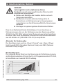
Abbreviations
2-wire The lead resistance is recorded as an error in the measurement.
3-wire With a cable length of 30 m or longer, measuring errors can
occur.
4-wire The lead resistance can be neglected.
1. General information

EN
14073818.09 07/2018 EN/DE/FR/ES
6 WIKA operating instructions model TR33
2. Safety
WARNING!
Before installation, commissioning and operation, ensure
that the appropriate resistance thermometer has been
selected in terms of measuring range, design, specic
measuring conditions and appropriate wetted parts' materials
(corrosion).
Non-observance can result in serious injury and/or damage
to the equipment.
Depending on the type of application, the electrical
connection must be protected against mechanical damage.
Further important safety instructions can be found in the
individual chapters of these operating instructions.
2.1 Intendeduse
The model TR33 resistance thermometer is used as a general-
purpose thermometer for the measurement of temperatures from
-50 … +150 °C or -58 ... +302 °F (without neck tube) and -50 … +250 °C
or -58 ... +482 °F (with neck tube) in liquid and gaseous media. It can be
used for pressures up to 140 bar with 3 mm sensor diameters and up
to 270 bar with 6 mm sensor diameters, dependent on the instrument
version.
The instrument has been designed and built solely for the intended use
described here, and may only be used accordingly.
The technical specications contained in these operating instructions
must be observed. Improper handling or operation of the instrument
outside of its technical specications requires the instrument to be taken
out of service immediately and inspected by an authorised WIKA service
engineer.
2. Safety

EN
WIKA operating instructions model TR33
14073818.09 07/2018 EN/DE/FR/ES
7
If the instrument is transported from a cold into a warm environment, the
formation of condensation may result in instrument malfunction. Before
putting it back into operation, wait for the instrument temperature and the
room temperature to equalise.
The manufacturer shall not be liable for claims of any type based on
operation contrary to the intended use.
2.2 Personnelqualication
WARNING!
Riskofinjuryshouldqualicationbeinsucient!
Improper handling can result in considerable injury and
damage to equipment.
■
The activities described in these operating instructions
may only be carried out by skilled personnel who have the
qualications described below.
■
Keep unqualied personnel away from hazardous areas.
Skilled electrical personnel
Skilled electrical personnel are understood to be personnel who,
based on their technical training, know-how and experience as well
as their knowledge of country-specic regulations, current standards
and directives, are capable of carrying out work on electrical systems
and independently recognising and avoiding potential hazards. The
skilled electrical personnel have been specically trained for the work
environment they are working in and know the relevant standards and
regulations. The skilled electrical personnel must comply with current
legal accident prevention regulations.
Special operating conditions require further appropriate knowledge, e.g.
of aggressive media.
2. Safety

EN
14073818.09 07/2018 EN/DE/FR/ES
8 WIKA operating instructions model TR33
2.3 Special hazards
WARNING!
For hazardous media such as oxygen, acetylene,
ammable or toxic gases or liquids, and refrigeration plants,
compressors, etc., in addition to all standard regulations,
the appropriate existing codes or regulations must also be
followed.
WARNING!
Protection from electrostatic discharge (ESD) required!
The proper use of grounded work surfaces and personal
wrist straps is required when working with exposed circuitry
(printed circuit boards), in order to prevent static discharge
from damaging sensitive electronic components.
To ensure safe working on the instrument, the operating
company must ensure
■
that suitable rst-aid equipment is available and aid is
provided whenever required.
■
that the operating personnel are regularly instructed in all
topics regarding work safety, rst aid and environmental
protection and know the operating instructions and in
particular, the safety instructions contained therein.
DANGER!
Danger of death caused by electric current
Upon contact with live parts, there is a direct danger of death.
■
Electrical instruments may only be installed and
connected by skilled electrical personnel.
■
Operation using a defective power supply unit (e.g. short
circuit from the mains voltage to the output voltage) can
result in life-threatening voltages at the instrument!
2. Safety

EN
WIKA operating instructions model TR33
14073818.09 07/2018 EN/DE/FR/ES
9
WARNING!
Residual media in dismounted instruments can result in a
risk to persons, the environment and equipment.
Take sucient precautionary measures.
Do not use this instrument in safety or emergency stop
devices. Incorrect use of the instrument can result in injury.
Should a failure occur, aggressive media with extremely high
temperature and under high pressure or vacuum may be
present at the instrument.
2.4 Labelling, safety marks
Productlabel(example)
2. Safety
Model
Date of manufacture (Year-Month)
Approval logos
Information on version (measuring element, output signal, measuring range...)
■
Thermometer with transmitter and 4 ... 20 mA output signal
■
Thermometer with direct sensor output with Pt100 and Pt1000
Serial number, TAG number
Before mounting and commissioning the instrument,
ensure you read the operating instructions!

EN
14073818.09 07/2018 EN/DE/FR/ES
10 WIKA operating instructions model TR33
3. Specications
Thermometerwithtransmitterandoutputsignal4...20mA
Temperature range Without neck tube -30 ... +150 °C (-22 ... +302 °F),
with neck tube -30 ... +250 °C (-22 ... +482 °F)
1)
Measuring element Pt1000
Connection method 2-wire
Tolerancevalueofthe
measuring element
Class A
(per IEC 60751)
Measuringdeviationofthe
transmitter
0.25 K
(per IEC 60770)
Totalmeasuringdeviationin
accordancewithIEC60770
Measuring deviation of the measuring element +
the transmitter
Measuring span Minimum 20 K, maximum 300 K
Basicconguration Measuring range 0 ... 150 °C (-32 ... +302 °F),
other measuring ranges are adjustable
Analogueoutput 4 ... 20 mA, 2-wire
Linearisation Linear to temperature per IEC 60751
Linearisation error ±0.1 %
2)
Switch-ondelay,electrical Max. 4 s (time before the rst measured value)
Warming-up period After approx. 4 minutes, the instrument will
function to the specications (accuracy) given in
the data sheet.
Current signal for fault
signal
Congurable in accordance with NAMUR NE43
downscale ≤ 3.6 mA
upscale ≥ 21.0 mA
Sensor short-circuit Not congurable, in accordance with NAMUR NE43
downscale ≤ 3.6 mA
Sensor current < 0.3 mA (self-heating can be neglected)
Load R
A
R
A
≤ (U
B
- 10 V) / 23 mA with R
A
in Ω and U
B
in V
Eectofload ±0.05 % / 100 Ω
PowersupplyU
B
DC 10 ... 30 V
Max.permissibleresidual
ripple
10 % generated by U
B
< 3 % ripple of the output
current
Powersupplyinput Protected against reverse polarity
Powersupplyeect ±0.025 % / V (depending on the power supply)
3.Specications

EN
WIKA operating instructions model TR33
14073818.09 07/2018 EN/DE/FR/ES
11
Thermometerwithtransmitterandoutputsignal4...20mA
Electromagnetic
compatibility(EMC)
4)
EN 61326 emission (group 1, class B)
3)
, and
interference immunity (industrial application),
conguration at 20 % of the full measuring range
Temperature units Congurable °C, °F, K
Infodata TAG No., descriptor and user message can be
stored in transmitter
Congurationand
calibration data
Permanently stored
Electrical connection M12 x 1 circular connector (4-pin)
Readings in % refer to the measuring span
For a correct determination of the overall measuring deviation, both sensor and transmitter
measuring deviations have to be considered.
1) The temperature transmitter should therefore be protected from temperatures over 85 °C (185 °F).
2) ±0.2 % for measuring ranges with a lower limit less than 0 °C (32 °F)
3) Use resistance thermometers with shielded cable and ground the shield at at least one end
of the lead if the lines are longer than 30 m or leave the building. Operate the instrument in a
grounded state.
4) During transient interferences (e.g. burst, surge, ESD) take into account an increased
measuring deviation of up to 2 %.
ThermometerwithdirectsensoroutputwithPt100andPt1000
Temperature range
■
Class A
■
Class B
Without neck tube -30 ... +150 °C (-22 ... +302 °F)
With neck tube -30 ... +250 °C (-22 ... +482 °F)
Without neck tube -50 ... +150 °C (-58 ... +302 °F)
With neck tube -50 ... +250 °C (-58 ... +482 °F)
Temperature at the connector Max. 85 °C (185 °F)
Measuring element
■
Pt100 (measuring current: 0.1 ... 1.0 mA)
■
Pt1000 (measuring current: 0.1 ... 0.3 mA)
Connection method
■
2-wire
■
3-wire
■
4-wire
Tolerancevalueofthemeas-
uringelementperIEC60751
■
Class A
■
Class B at 2-wire
Electrical connection M12 x 1 circular connector (4-pin)
For detailed specications for Pt sensors, see Technical information IN 00.17 at
www.wika.com.
3.Specications

EN
14073818.09 07/2018 EN/DE/FR/ES
12 WIKA operating instructions model TR33
Case
Material Stainless steel
Ingressprotection
■
Case with connected connector
5) 6)
■
Coupler connector, not connected
IP67 and IP69 per IEC/EN 60529,
IP69K per ISO 20653
IP67 per IEC/EN 60529
Weight in kg ca. 0.2 ... 0.7 (depending on version)
Dimensions see “Dimensions in mm”
Ambientconditions
Ambienttemperaturerange
■
Models TR33-Z-Px, TR33-Z-Sx
■
Model TR33-Z-TT
-50 ... +85 °C (-58 ... +185 °F)
-40 ... +85 °C (-40 ... +185 °F)
Storage temperature range -40 ... +85 °C (-40 ... +185 °F)
ClimateclassperIEC60654-1
■
Models TR33-Z-Px, TR33-Z-Sx
■
Model TR33-Z-TT
Cx (-50 ... +85 °C or -58 ... +185 °F,
5 ... 95 % r. h.)
Cx (-40 ... +85 °C or -40 ... +185 °F,
5 ... 95 % r. h.)
Maximumpermissiblehumidity
perIEC60068-2-30var.2
100 % r. h., condensation allowed
Maximumoperatingpressure
7)8)
140 bar with 3 mm sensor diameter
270 bar with 6 mm sensor diameter
VibrationresistanceperIEC60751 10 ... 2,000 Hz, 20 g
7)
Shock resistance
perIEC60068-2-27
50 g, 6 ms, 3 axis, 3 faces, 3 times for
each face
Salt fog IEC 60068-2-11
5) The stated ingress protection only applies when plugged in using mating connectors that have
the appropriate ingress protection.
6) Not tested at UL
7) Dependent on the instrument version
8) Reduced operating pressure when using a compression tting:
Stainless steel: max. 100 bar PTFE: max. 8 bar
3.Specications

EN
WIKA operating instructions model TR33
14073818.09 07/2018 EN/DE/FR/ES
13
Patents, property rights
M12x1adaptertoangularconnector
DINEN175301-803
No. 001370985
Conditionsforoutdooruse(forULapprovalonly)
■
The instrument is suitable for applications with pollution degree 3.
■
The power supply must be suitable for operation above 2,000 m
should the temperature transmitter be used at this altitude.
■
The instrument shall be installed in locations sheltered from the
weather.
■
The instrument shall be installed “sun/UV radiation protected”.
For further specications see WIKA data sheet TE 60.33 and the order
documentation.
4. Design and function
4.1 Description
The model TR33 resistance thermometer consists of a thermowell with
a xed process connection and is screwed directly into the process.
It is designed to be impact and vibration resistant and all electrical
components are protected against humidity (IP67 or IP69K).
The vibration resistance conforms to IEC 60751 (20 g, dependent on
the instrument version). The impact resistance of all versions meets
the requirements of IEC 60751. Ensure that mechanical loads on the
connector are minimised, especially in case of increased ambient
temperatures or strong vibration loads.
The electrical connection is made via an M12 x 1 circular connector.
An adapter for electrical connection with angular connector per
DIN EN 175301-803 is optionally available.
3.Specications/4.Designandfunction

EN
14073818.09 07/2018 EN/DE/FR/ES
14 WIKA operating instructions model TR33
X
X
X
X
140069565.02
without neck tube
without process
connection
with compression
tting
with neck tube
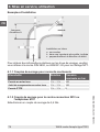
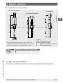
Legend:
A (U
1
) Insertion length
N (M
H
) Neck length
X Height process connection
Ød Sensor diameter
4. Design and function
1) For process temperature > 150 °C (302 °F) a neck length
N (M
H
) of 70 mm is required, otherwise N (M
H
) selectable
(55, 65 or 70 mm).
Thread Height process connection X
G1/2 11
G3/8 11
G1/4 10
M12 11
M20 11
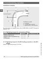
4.2 Dimensions in mm
■
Process connection with parallel threads (or without process connection)

EN
WIKA operating instructions model TR33
14073818.09 07/2018 EN/DE/FR/ES
15
X
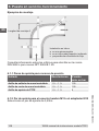
■
Process connection with tapered thread
4.3 Scopeofdelivery
Cross-check scope of delivery with delivery note.
140069565.02
Legend:
A (U
2
) Insertion length
N (M
H
) Neck length
X Height process connection
Ød Sensor diameter
without neck tube
with compression tting
with neck tube
4. Design and function
1) For process temperature > 150 °C (302 °F) a neck length
N (M
H
) of 70 mm is required, otherwise N (M
H
) selectable
(55, 65 or 70 mm).
Thread Height process connection X
1/4NPT 15
1/2NPT 19

EN
14073818.09 07/2018 EN/DE/FR/ES
16 WIKA operating instructions model TR33
5. Transport, packaging and storage
5.1 Transport
Check the instrument for any damage that may have been caused by
transport. Obvious damage must be reported immediately and damaged
instruments must not be used.
5.2 Packaging
Do not remove packaging until just before mounting.
Keep the packaging as it will provide optimum protection during transport
(e.g. change in installation site, sending for repair).
5.3 Storage
Permissibleconditionsattheplaceofstorage:
■
Storage temperature: -40 ... +85 °C (-40 ... +185 °F)
■
Humidity: 5 ... 95 % r. h.
Avoidexposuretothefollowingfactors:
■
Direct sunlight or proximity to hot objects
■
Mechanical vibration, mechanical shock (putting it down hard)
■
Soot, vapour, dust and corrosive gases
■
Potentially explosive environments, ammable atmospheres
Store the instrument in its original packaging in a location that fulls the
conditions listed above. If the original packaging is not available, pack
and store the instrument as described below:
1. Wrap the instrument in an antistatic plastic lm.
2. Place the instrument along with shock-absorbent material in the
packaging.
3. If stored for a prolonged period of time (more than 30 days), place a
bag containing a desiccant inside the packaging.
WARNING!
Before storing the instrument (following operation), remove
any residual media. This is of particular importance if
the medium is hazardous to health, e.g. caustic, toxic,
carcinogenic, radioactive, etc.
5. Transport, packaging and storage

EN
WIKA operating instructions model TR33
14073818.09 07/2018 EN/DE/FR/ES
17
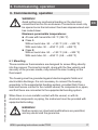
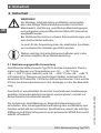
6. Commissioning, operation
WARNING!
Avoid putting any mechanical loading on the electrical
connections and on the enclosures. Connections must only
be opened once the instrument has been depressurised and
has cooled down.
Maximumpermissibletemperatures:
■
At case with transmitter: 85 °C (185 °F)
■
Class A:
Without neck tube -30 ... +150 °C (-22 ... +302 °F)
With neck tube -30 ... +250 °C (-22 ... +482 °F)
■
Class B:
Without neck tube -50 ... +150 °C (-58 ... +302 °F)
With neck tube -50 ... +250 °C (-58 ... +482 °F)
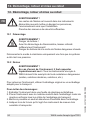
6.1 Mounting
These resistance thermometers are designed for screw-tting directly
into the process. The insertion length, along with the ow velocity and
viscosity of the process media, may reduce the max. loading on the
thermowell.
The housing must be grounded against electromagnetic elds and
electrostatic discharge. It is not necessary to connect the housing
separately to the equipotential bonding system, provided that it has a
xed and secure contact to the metallic vessel, its components or pipes,
and that these are connected to the equipotential bonding system.
When there is a non-metallic contact with the vessel, or with its
structural components or piping, the instrument must be provided with
equipotential bonding.
WARNING!
Neither repairs nor structural modications are permitted,
and any would void the guarantee.
6. Commissioning, operation

EN
14073818.09 07/2018 EN/DE/FR/ES
18 WIKA operating instructions model TR33
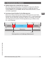
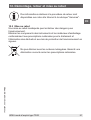
Installation on pipes
a on elbows
b in smaller pipe, inclined
c perpendicular to ow direction
Insertion length A
Installationexamples
For information on tapped holes, refer to DIN 3852 or for NPT threads to
ANSI B 1.20.
6.1.1 Tighteningtorquesforcompressionttings
Sealing Rotation Max.pressureinbar
Stainless steel ferrule 1 ¼ ... 1 ½ 100
Stainless steel compression ring 1 ¼ ... 1 ½ 100
PTFE ferrule 1 ¼ ... 1 ½ 8
6.1.2 Tightening torque for the M12 mating connector or the M12
adapter
Select a tightening torque of 0.6 Nm.
6. Commissioning, operation

EN
WIKA operating instructions model TR33
14073818.09 07/2018 EN/DE/FR/ES
19
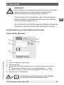
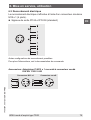
6.2 Electrical connection
The electrical connection is made via a M12 x 1 (4-pin) circular
connector.
■
Output signal Pt100 and Pt1000 (standard)
6. Commissioning, operation
mA
4 ... 20 mA
M12x1connector Angularconnector
Accessories:M12x1PtadaptertoDINEN175301-803angularconnector
Alternative pin assignments possible.
For further information see order documentation.

EN
14073818.09 07/2018 EN/DE/FR/ES
20 WIKA operating instructions model TR33
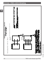
6. Commissioning, operation
■
Output signal 4 ... 20 mA (standard)
Pin Signal Description
1 L+ 10 ... 30 V
2 VQ not connected
3 L- 0 V
4 C not connected
M12x1connector Angularconnector
mA
4 ... 20 mA
Accessories:M12x1transmitteradaptertoDINEN175301-803
angular connector
Pin assignment angular connector
Pin Signal Description
1 L+ 10 ... 30 V
2 L- 0 V
3 VQ not connected
4 C not connected
Alternative pin assignments possible.
For further information see order documentation.
La page est en cours de chargement...
La page est en cours de chargement...
La page est en cours de chargement...
La page est en cours de chargement...
La page est en cours de chargement...
La page est en cours de chargement...
La page est en cours de chargement...
La page est en cours de chargement...
La page est en cours de chargement...
La page est en cours de chargement...
La page est en cours de chargement...
La page est en cours de chargement...
La page est en cours de chargement...
La page est en cours de chargement...
La page est en cours de chargement...
La page est en cours de chargement...
La page est en cours de chargement...
La page est en cours de chargement...
La page est en cours de chargement...
La page est en cours de chargement...
La page est en cours de chargement...
La page est en cours de chargement...
La page est en cours de chargement...
La page est en cours de chargement...
La page est en cours de chargement...
La page est en cours de chargement...
La page est en cours de chargement...
La page est en cours de chargement...
La page est en cours de chargement...
La page est en cours de chargement...
La page est en cours de chargement...
La page est en cours de chargement...
La page est en cours de chargement...
La page est en cours de chargement...
La page est en cours de chargement...
La page est en cours de chargement...
La page est en cours de chargement...
La page est en cours de chargement...
La page est en cours de chargement...
La page est en cours de chargement...
La page est en cours de chargement...
La page est en cours de chargement...
La page est en cours de chargement...
La page est en cours de chargement...
La page est en cours de chargement...
La page est en cours de chargement...
La page est en cours de chargement...
La page est en cours de chargement...
La page est en cours de chargement...
La page est en cours de chargement...
La page est en cours de chargement...
La page est en cours de chargement...
La page est en cours de chargement...
La page est en cours de chargement...
La page est en cours de chargement...
La page est en cours de chargement...
La page est en cours de chargement...
La page est en cours de chargement...
La page est en cours de chargement...
La page est en cours de chargement...
La page est en cours de chargement...
La page est en cours de chargement...
La page est en cours de chargement...
La page est en cours de chargement...
La page est en cours de chargement...
La page est en cours de chargement...
La page est en cours de chargement...
La page est en cours de chargement...
La page est en cours de chargement...
La page est en cours de chargement...
La page est en cours de chargement...
La page est en cours de chargement...
La page est en cours de chargement...
La page est en cours de chargement...
La page est en cours de chargement...
La page est en cours de chargement...
La page est en cours de chargement...
La page est en cours de chargement...
La page est en cours de chargement...
La page est en cours de chargement...
La page est en cours de chargement...
La page est en cours de chargement...
La page est en cours de chargement...
La page est en cours de chargement...
La page est en cours de chargement...
La page est en cours de chargement...
La page est en cours de chargement...
La page est en cours de chargement...
La page est en cours de chargement...
La page est en cours de chargement...
La page est en cours de chargement...
La page est en cours de chargement...
La page est en cours de chargement...
La page est en cours de chargement...
La page est en cours de chargement...
La page est en cours de chargement...
La page est en cours de chargement...
La page est en cours de chargement...
La page est en cours de chargement...
La page est en cours de chargement...
La page est en cours de chargement...
La page est en cours de chargement...
La page est en cours de chargement...
La page est en cours de chargement...
-
 1
1
-
 2
2
-
 3
3
-
 4
4
-
 5
5
-
 6
6
-
 7
7
-
 8
8
-
 9
9
-
 10
10
-
 11
11
-
 12
12
-
 13
13
-
 14
14
-
 15
15
-
 16
16
-
 17
17
-
 18
18
-
 19
19
-
 20
20
-
 21
21
-
 22
22
-
 23
23
-
 24
24
-
 25
25
-
 26
26
-
 27
27
-
 28
28
-
 29
29
-
 30
30
-
 31
31
-
 32
32
-
 33
33
-
 34
34
-
 35
35
-
 36
36
-
 37
37
-
 38
38
-
 39
39
-
 40
40
-
 41
41
-
 42
42
-
 43
43
-
 44
44
-
 45
45
-
 46
46
-
 47
47
-
 48
48
-
 49
49
-
 50
50
-
 51
51
-
 52
52
-
 53
53
-
 54
54
-
 55
55
-
 56
56
-
 57
57
-
 58
58
-
 59
59
-
 60
60
-
 61
61
-
 62
62
-
 63
63
-
 64
64
-
 65
65
-
 66
66
-
 67
67
-
 68
68
-
 69
69
-
 70
70
-
 71
71
-
 72
72
-
 73
73
-
 74
74
-
 75
75
-
 76
76
-
 77
77
-
 78
78
-
 79
79
-
 80
80
-
 81
81
-
 82
82
-
 83
83
-
 84
84
-
 85
85
-
 86
86
-
 87
87
-
 88
88
-
 89
89
-
 90
90
-
 91
91
-
 92
92
-
 93
93
-
 94
94
-
 95
95
-
 96
96
-
 97
97
-
 98
98
-
 99
99
-
 100
100
-
 101
101
-
 102
102
-
 103
103
-
 104
104
-
 105
105
-
 106
106
-
 107
107
-
 108
108
-
 109
109
-
 110
110
-
 111
111
-
 112
112
-
 113
113
-
 114
114
-
 115
115
-
 116
116
-
 117
117
-
 118
118
-
 119
119
-
 120
120
-
 121
121
-
 122
122
-
 123
123
-
 124
124


WIKA TR33 Mode d'emploi
- Catégorie
- Thermomètres corporels numériques
- Taper
- Mode d'emploi
dans d''autres langues
- español: WIKA TR33 Instrucciones de operación
- Deutsch: WIKA TR33 Bedienungsanleitung