Roper Dishwasher Undercounter Dishwasher Manuel utilisateur
- Catégorie
- Lave-vaisselle
- Taper
- Manuel utilisateur
Ce manuel convient également à

Installation Instructions
Undercounter Dishwasher
(Plastic Giant Tub Models)
8575348
Instructions d'installation
Lave-vaisselle encastré
(modèles à très grande cuve en plastique)
Table of Contents.............................................................................2
Table des matières.........................................................................17

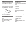
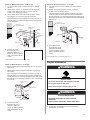
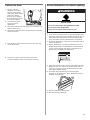
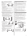
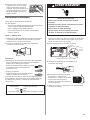
You need to:
• Slowly open dishwasher door while someone grasps the
rear of the dishwasher. Remove shipping materials, drain
hose and lower rack. Close dishwasher door until latched.
• Observe all governing codes and ordinances.
• Install this dishwasher as specified in these instructions.
• Installation should be performed by a qualified service
technician. The dishwasher must be installed to meet all
electrical and plumbing national and local codes and
ordinances.
WARNING
Tip Over Hazard
Do not use dishwasher until completely installed.
Do not push down on open door.
Doing so can result in serious injury or cuts.
2
Table of Contents
Dishwasher Safety . . . . . . . . . . . . . . . . . . . . . . . . . . . . . . . . . 2
Installation Requirements . . . . . . . . . . . . . . . . . . . . . . . . . . . 3
Tools and parts . . . . . . . . . . . . . . . . . . . . . . . . . . . . . . . . . 3
Location Requirements . . . . . . . . . . . . . . . . . . . . . . . . . . 3
Drain Requirements . . . . . . . . . . . . . . . . . . . . . . . . . . . . . 5
Water Supply Requirements . . . . . . . . . . . . . . . . . . . . . . 5
Electrical Requirements . . . . . . . . . . . . . . . . . . . . . . . . . . 5
You can be killed or seriously injured if you don't immediately
You
can be killed or seriously injured if you don't
follow
All safety messages will tell you what the potential hazard is, tell you how to reduce the chance of injury, and tell you what can
happen if the instructions are not followed.
Your safety and the safety of others are very important.
We have provided many important safety messages in this manual and on your appliance. Always read and obey all safety
messages.
This is the safety alert symbol.
This symbol alerts you to potential hazards that can kill or hurt you and others.
All safety messages will follow the safety alert symbol and either the word “DANGER” or “WARNING.”
These words mean:
follow instructions.
instructions.
DANGER
WARNING
Dishwasher Safety
Installation Instructions. . . . . . . . . . . . . . . . . . . . . . . . . . . . . 6
Prepare cabinet opening
using existing utility hookups . . . . . . . . . . . . . . . . . . . . . 6
Prepare cabinet opening
where there are no existing utility hookups. . . . . . . . . . 7
Prepare dishwasher . . . . . . . . . . . . . . . . . . . . . . . . . . . . . 9
Make electrical connection. . . . . . . . . . . . . . . . . . . . . . . 11
Connect to water supply . . . . . . . . . . . . . . . . . . . . . . . . 12
Connect to drain . . . . . . . . . . . . . . . . . . . . . . . . . . . . . . . 13
Secure dishwasher in cabinet opening. . . . . . . . . . . . . 13

3
® Teflon is a registered trademark of E.I. Du Pont de Nemours and
Company.
Tools needed:
• electric drill with 1/2", 3/4"
and 1-1/2" hole saw bits
• small tubing cutter
• wire stripper
• 1-1/2"-2" screw-type clamp
if connecting to waste-tee
Parts needed:
• copper tubing (3/8"
recommended) or flexible
stainless steel braided fill
line
• clamp connector or
conduit connector to fit a
7/8" (2.2 cm) diameter hole
Tools needed:
• pliers
• Phillips screwdriver
• 5/16" and 1/4" nut drivers
or hex sockets
• measuring tape or ruler
• 10" adjustable wrench that
opens to 1-1/8" (2.9 cm)
• flat-blade screwdriver
• utility knife
• 2 twist-on wire connectors
which are the proper size
to connect your household
wiring to 16-gauge wiring
in dishwasher
• small level
• flashlight
• shallow pan
• 5/8" open-end wrench
• bath towel
• wood block
Parts needed:
• 90° elbow with 3/8" N.P.T.
external threads on one
end. (The other end must
fit your water supply line.)
• Teflon
®
tape or pipe joint
compound
• shims (if installed with
built-up floor)
Tools and Parts
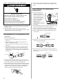
Gather the required tools and parts before starting
installation.
All installations
In addition, for new installations
A
B
C
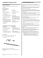
Parts supplied
A. 2 – drain hose clamps, 1 large and 1 small
B. 2 – # 10 x 1/2" Phillips-head screws
C. drain hose
Make sure all these parts are included.
See separate parts list for accessories available for your
dishwasher.
Installation Requirements
Location Requirements
Do not run drain lines, water lines or electrical wiring
where they can interfere with or contact dishwasher motor
or legs.
The location where the dishwasher will be installed must
provide clearance between motor and flooring. Motor
should not touch the floor.
Do not install dishwasher over carpeted flooring.
Protect dishwasher and water lines leading to dishwasher
against freezing. Damage from freezing is not covered by
the warranty.
A side panel kit is available from your dealer for installing
your dishwasher at the end of your cabinetry.
A moisture barrier accessory (Part No. 4396277) is available
from your dealer for installing underneath the countertop,
but is not required.
Check location where dishwasher will be installed. The
location must provide:
• easy access to water, electricity and drain.
• convenient access for loading and unloading dishes.
Corner locations require a 2" (5.1 cm) minimum clearance
between the side of the dishwasher door and the wall or
cabinet.
• square opening for proper operation and appearance.
• cabinet front perpendicular to floor.
• level floor. (If floor at front of opening is not level with
floor at rear of opening, shims may be needed to level
dishwasher.)
NOTE:To prevent shifting during dishwasher operation,
shims must be securely attached to the floor.
If dishwasher will be left unused for a period of time or in a
location where it may be subject to freezing, have it
winterized by authorized service personnel.
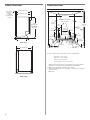
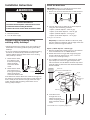
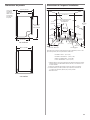
Make sure pipes, wires and drain hose are within the
shaded area shown in the “Cutout dimensions” section.
Helpful Tip: If the floor in the dishwasher opening is
uneven (example: tile flooring only partway into
opening) you will need to take special care in
measuring dimensions and in leveling dishwasher.

3/4" (1.9 cm)
insulation –
may be
compressed
(not used on all
models)
25-1/4" (64.1 cm)
24-1/2" (62.2 cm)
21" (53.3 cm)
33-7/8"
(86 cm) min.
with wheels
removed
4
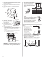
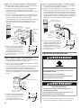
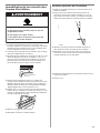
Cut holes in shaded area of cabinet walls or floor as specified below:
water line – 1/2" (1.3 cm)
drain line – 1-1/2" (3.8 cm)
direct wire – 3/4" (1.9 cm)
power supply cord – 1-1/2" (3.8 cm)
* Measured from the lowest point on the underside of countertop. May be
reduced to 33-7/8" (86 cm) by removing wheels from dishwasher.
** Minimum, measured from narrowest point of opening.
*** May be increased to 6-7/8" (17.5 cm) if height of opening is 34-1/2" (87.6 cm)
at its lowest point.
‡ Both sides
Cutout dimensionsProduct dimensions
23-7/8" (60.6 cm)
SIDE VIEW
REAR VIEW
9"
(22.9 cm)
10"
(25.4 cm)
6-1/4"
(15.9 cm)***
6-1/4"
(15.9 cm)‡***
2"
(5.1 cm)‡
2-1/2"
(6.4 cm)‡
4"
(10.2 cm)‡
10-1/2"
(26.7 cm)
6-3/4"
(17.2 cm)‡
3"
(7.6 cm)‡
2"
(5.1 cm)
clear area‡
4-1/4"
(10.8 cm)‡
1-3/4"
(4.4 cm)‡
1-3/4"
(4.4 cm)‡
24"
(61 cm)
min.
24" (61 cm)**
All surfaces must be free
from intrusions
34"
(86.4 cm)
min.*
3"
(7.6 cm)‡

5
Drain Requirements
• Use the new drain hose supplied with your dishwasher.
If this is not long enough, use a new drain hose with a
maximum length of 12 feet (3.7 m) that meets all
current AHAM/IAPMO test standards, is resistant to
heat and detergent, and fits the 1" (2.5 cm) drain
connector of the dishwasher.
• Connect drain hose to waste tee or disposer inlet
above drain trap in house plumbing and 20" (50.8 cm)
minimum above the floor. It is recommended that the
drain hose either be looped up and securely fastened
to the underside of the counter, or be connected to an
air gap.
• Use an air gap if the drain hose is connected to house
plumbing lower than 20" (50.8 cm) above subfloor or
floor.
• Use 1/2" minimum I.D. drain line fittings.
Water Supply Requirements
• A hot water line with 20-120 psi (138-862 kPa) water
pressure.
• 120°F (49°C) water at dishwasher.
• 3/8" O.D. copper tubing with compression fitting or
flexible stainless steel braided fill line (1/2" minimum
plastic tubing is not recommended).
• A 90° elbow with 3/8" N.P.T. external pipe threads on
one end.
Do not solder within 6" (15.2 cm) from water inlet valve.
Electrical Requirements
Contact a qualified electrician.
Assure that the electrical installation is adequate and in
conformance with all national and local codes and
ordinances.
You must have:
• 120-volt, 60 Hz, AC-only, 15 or 20 amp., fused electrical
supply.
• Copper wire only.
We recommend:
• A time-delay fuse or circuit breaker.
• A separate circuit.
If direct wiring dishwasher:
• Use flexible, armored or non-metallic sheathed, copper
wire with grounding wire that meets the wiring
requirements for your home and local codes and
ordinances.
• Use strain relief method provided with house wiring
junction box or install a U.L.-listed/CSA-certified clamp
connector to the house wiring junction box. If using
conduit, use a U.L.-listed/CSA-certified conduit connector.
If connecting dishwasher with a power supply cord:
• Use Power Supply Cord Kit (Part No. 4317824) marked for
use with dishwashers. Kit contents include:
– Volex, Inc., UL listed 16 gauge 3 wire power supply
cord with 3 prong grounded plug.
– Neer C-500 7/8 inch strain relief.
– 3 wire connectors.
– Part No. 302797 grommet
Follow the kit instructions for installing the power
supply cord.
• Power supply cord must plug into a mating three prong,
grounded outlet, located in the cabinet next to the
dishwasher opening. Outlet must meet all local codes and
ordinances.
air gap

6
Installation Instructions
1. Disconnect power.
2. Turn off water supply.
Prepare cabinet opening using
existing utility hookups
• Follow the steps in this section if you are installing the
dishwasher in an existing cabinet opening with utility
hookups.
• If you are installing the dishwasher in a cabinet opening
that does not have hookups, follow the steps under
"Prepare cabinet opening where there are no existing
utility hookups" section.
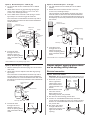
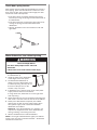
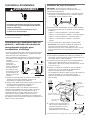
1. Check that the water
line reaches to the
front left of opening
where the water
connection will be
made.
2. Check that the direct
wire reaches to the
front right of opening
where the electrical
connection will be made.
If the water line and the direct wire reach far enough into
the opening, proceed to the next section “Install the drain
hose.“ If they do not reach far enough, follow the steps
under “Prepare cabinet opening where there are no
existing utility hookups.”
6" (15.2 cm)
water
line
direct
wire
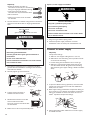
WARNING
Disconnect electrical power at the fuse box or circuit
breaker box before installing dishwasher.
Failure to do so can result in death or electrical shock.
Electrical Shock Hazard
Install the drain hose
IMPORTANT: Always use a new drain hose even when
installing a new replacement dishwasher.
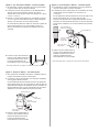
1. Drill a 1-1/2" (3.8 cm) diameter hole in cabinet wall or
floor on the side of the opening closest to the sink.
2. Connect drain hose to waste tee or waste disposer
using one of the following methods:
• Option 1, Waste disposer – with air gap
• Option 2, No waste disposer – with air gap
• Option 3, Waste disposer – no air gap*
• Option 4, No waste disposer – no air gap*
*an air gap is recommended
Helpful Tip:To reduce the vibration of the hose, keep
the hose away from the floor and the edge of the hole
where it passes through the cabinet.
Option 1, Waste disposer – with air gap:
1. Remove the disposer knockout plug. Cut end of drain
hose if needed (do not cut ribbed section).
2. Attach drain hose to air gap with large spring-type
clamp. If the drain hose was cut, use a 1-1/2" to 2"
(3.8 to 5 cm) screw-type clamp*.
3. Use a rubber hose connector* with spring or screw-
type clamps* to connect air gap to disposer inlet.
This connection must be before the drain trap and at
least 20" (50.8 cm) above the floor where dishwasher
will be installed.
4. Insert drain hose
through hole cut in
cabinet to the front
center of opening where
drain connection will be
made.
* Parts available from local plumbing supply stores
drain
hose
large
spring-type
clamp
air gap
rubber hose
connector
disposer
inlet
drain trap
drain hose –
cut here if needed
spring or
screw-type
clamps

7
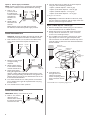
Prepare cabinet opening where there
are no existing utility hookups
Electrical connection
Option1, Direct wire method:
Helpful Tip: Wiring the dishwasher will be easier if you
route wire into the cabinet opening from the right side.
1. Drill a 3/4" (1.9 cm)
hole in right-hand
cabinet side, rear or
floor. Preferred and
optional locations are
shown.
2. Wood cabinet: Sand
hole until smooth.
Metal cabinet: Cover
hole with grommet, not provided.
3. Run wire into house wiring junction box.
4. Install a U.L.-listed/CSA-certified clamp connector
(strain relief) for flexible-type wire. If installing conduit,
attach a U.L.-listed/CSA-certified conduit connector to
the junction box.
5. Run other end of wire
through cabinet hole.
Cable must extend to the
right front of cabinet
opening.
preferred
locations
optional
locations
Option 3, Waste disposer – no air gap:
1. Remove the disposer knockout plug. Do not cut end of
drain hose.
2. Attach drain hose to disposer inlet with large spring-
type clamp.
This connection must be before the drain trap and at
least 20" (50.8 cm) above the floor where dishwasher
will be installed. It is recommended that the drain hose
be looped up and securely fastened to the underside of
the counter.
3. Insert drain hose
through hole cut in
cabinet to the front
center of opening where
drain connection will be
made.
drain hose
large spring-type
clamp
disposer
inlet
drain trap
Option 4, No waste disposer – no air gap:
1. Cut end of drain hose if needed (do not cut ribbed
section).
2. Attach drain hose to waste tee with 1-1/2" to 2"
(3.8 to 5 cm) screw-type clamp*.
This connection must be before the drain trap and at
least 20" (50.8 cm) above the floor where dishwasher
will be installed. It is recommended that the drain hose
be looped up and securely fastened to the underside of
the counter.
3. Insert drain hose
through hole cut in
cabinet to the front
center of opening where
drain connection will be
made.
* Parts available from local plumbing supply stores
drain
hose
waste
tee
drain trap
screw-type clamp
drain hose –
cut here if needed
Option 2, No waste disposer – with air gap:
1. Cut end of drain hose if needed (do not cut ribbed
section).
2. Attach drain hose to air gap with large spring-type
clamp. If the drain hose was cut, use a 1-1/2" to 2"
(3.8 to 5 cm) screw-type clamp*.
3. Use a rubber hose connector* with spring or screw-
type clamps* to connect air gap to waste tee.
This connection must be before the drain trap and at
least 20" (50.8 cm) above the floor where dishwasher
will be installed.
4. Insert drain hose
through hole cut in
cabinet to the front
center of opening where
drain connection will be
made.
* Parts available from local plumbing supply stores
drain hose –
cut here if needed
drain
hose
large
spring-type
clamp
air gap
rubber hose
connector
spring or
screw-type
clamps
waste
tee
drain trap
drain hose
drain hose
drain hose

8
Option 2, Power supply cord method:
NOTE: A mating, three prong, ground-type wall receptacle
is required in a cabinet next to the dishwasher opening.
1. Drill a 1-1/2"
(3.8 cm) hole in
the cabinet rear
or side. Preferred
and optional
locations are
shown.
2. Wood cabinet:
Sand hole until
smooth.
Metal cabinet: Cover hole with grommet (Part
No. 302797) included with power supply cord kit.
Install the water line
Helpful Tip: Routing the water line through the left side
of cabinet opening will make water connection easier.
1. Drill a minimum 1/2" (1.3 cm) hole in the cabinet side,
rear or floor. Preferred and optional locations are
shown.
2. Measure overall length
of copper tubing
required.
3. Attach copper tubing
to the water line with a
manual shutoff valve.
4. Slowly feed copper
tubing through hole in
cabinet. Copper tubing will bend and kink easily, so be
gentle. The copper tubing should be far enough into the
cabinet opening to connect it to dishwasher inlet on the
front left of the dishwasher.
5. Turn water shutoff valve to “ON” position. Flush water
into a shallow pan to get rid of particles that may clog
the inlet valve.
6. Turn shutoff valve to “OFF” position.
Install the drain hose
IMPORTANT: Always use a new drain hose.
1. Drill a 1-1/2" (3.8 cm)
diameter hole in
cabinet wall or floor on
the side of the opening
closest to the sink.
Option 1, Waste disposer – with air gap:
1. Remove the disposer knockout plug. Cut end of drain
hose if needed (do not cut ribbed section).
2. Attach drain hose to air gap with large spring-type
clamp. If the drain hose was cut, use a 1-1/2" to 2"
(3.8 to 5 cm) screw-type clamp*.
3. Use a rubber hose connector* with spring or screw-
type clamps* to connect air gap to disposer inlet.
This connection must be before the drain trap and at
least 20" (50.8 cm) above the floor where dishwasher
will be installed.
4. Insert drain hose
through hole cut in
cabinet to the front
center of opening where
drain connection will be
made.
* Parts available from local plumbing supply stores
copper
tubing
drain
hose
large
spring-type
clamp
air gap
rubber hose
connector
disposer
inlet
drain trap
drain hose –
cut here if needed
spring or
screw-type
clamps
preferred
locations
optional
locations
optional
locations
preferred
locations
2. Connect drain hose to waste tee or waste disposer
using one of the following methods:
• Option 1, Waste disposer – with air gap
• Option 2, No waste disposer – with air gap
• Option 3, Waste disposer – no air gap*
• Option 4, No waste disposer – no air gap*
*an air gap is recommended
Helpful Tip:To reduce the vibration of the hose, keep
the hose away from the floor and the edge of the hole
where it passes through the cabinet.
drain hose

9
Option 4, No waste disposer – no air gap:
1. Cut end of drain hose if needed (do not cut ribbed
section).
2. Attach drain hose to waste tee with 1-1/2" to 2"
(3.8 to 5 cm) screw-type clamp*.
This connection must be before the drain trap and at
least 20" (50.8 cm) above the floor where dishwasher
will be installed. It is recommended that the drain hose
be looped up and securely fastened to the underside of
the counter.
3. Insert drain hose
through hole cut in
cabinet to the front
center of opening where
drain connection will be
made.
* Parts available from local plumbing supply stores
1. Grasp sides of dishwasher door frame and put
dishwasher on its back.
Prepare dishwasher
drain
hose
waste
tee
drain trap
screw-type clamp
drain hose –
cut here if needed
WARNING
Tip Over Hazard
Do not use dishwasher until completely installed.
Do not push down on open door.
Doing so can result in serious injury or cuts.
WARNING
Excessive Weight Hazard
Use two or more people to move and install
dishwasher.
Failure to do so can result in back or other injury.
Option 2, No waste disposer – with air gap:
1. Cut end of drain hose if needed (do not cut ribbed
section).
2. Attach drain hose to air gap with large spring-type
clamp. If the drain hose was cut, use a 1-1/2" to 2"
(3.8 to 5 cm) screw-type clamp*.
3. Use a rubber hose connector* with spring or screw-
type clamps* to connect air gap to waste tee.
This connection must be before the drain trap and at
least 20" (50.8 cm) above the floor where dishwasher
will be installed.
4. Insert drain hose
through hole cut in
cabinet to the front
center of opening where
drain connection will be
made.
* Parts available from local plumbing supply stores
Option 3, Waste disposer – no air gap:
1. Remove the disposer knockout plug. Do not cut end of
drain hose.
2. Attach drain hose to disposer inlet with large spring-
type clamp.
This connection must be before the drain trap and at
least 20" (50.8 cm) above the floor where dishwasher
will be installed. It is recommended that the drain hose
be looped up and securely fastened to the underside of
the counter.
3. Insert drain hose
through hole cut in
cabinet to the front
center of opening where
drain connection will be
made.
drain hose –
cut here if needed
drain
hose
large
spring-type
clamp
air gap
rubber hose
connector
spring or
screw-type
clamps
waste
tee
drain trap
drain hose
large spring-type
clamp
disposer
inlet
drain trap

10
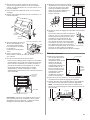
8. Measure height of cabinet opening
from underside of countertop to
floor where dishwasher will be
installed (you need the lowest
point). Check chart for that height
opening. Put wheels in the required
position.
9. Turn both front leveler legs to the same
height.
If the minimum cutout height is less than
34" (86.4 cm), the rear wheels can be
removed for additional clearance. This will
allow the dishwasher to fit into a 33-7/8"
(86 cm) high cutout, but the dishwasher
will be more difficult to move into
position. If the wheels are removed,
protect the floor when moving the dishwasher.
If you have built-up
floors
1. Measure height of opening
from underside of
countertop to built-up
floor. If the height is at
least 33-3/4" (85.7 cm), the
dishwasher will fit into the
opening without
modification to the
countertop or flooring.
2. Put wheels in position 1
and turn the front leveler legs up all the way.
3. Add shims as needed in the area shown to bring
dishwasher up to proper height.
NOTE: Shims must be securely attached to floor to
prevent their movement when the dishwasher is
operated.
1
2
3
10
5
0
Number of
turns on
front leg
Wheel
position
34" (86.4 cm)
34-1/4" (87 cm)
34-1/2" (87.6 cm)
Minimum
cutout height
front leg
2"
(5.1 cm)
6"
(15.2 cm)
2-3/4"
(7.0 cm)
2-3/4"
(7.0 cm)
shim
shim
shim
33-3/4"
(85.7 cm)
min.
countertop
built-up
floor
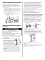
2. Remove two screws attaching access panel and lower
panel to dishwasher using a 1/4" hex socket, nut driver
or Phillips screwdriver.
3. Remove panels and set panels aside on a protective
surface.
4. Check that grounding clip is attached to the lower
panel.
5. Apply Teflon
®
tape or pipe
joint compound to 90° elbow
fitting and connect fitting to
water inlet valve.
6. Tighten elbow until snug, and
be sure that it faces to the
rear.
7. Remove terminal box cover.
– If you are direct wiring: install a U.L.-listed/CSA-
certified clamp connector to the terminal box. If using
conduit, use a U.L.-listed/CSA-certified conduit
connector.
– If you are installing a power supply cord kit, do so
now, following kit instructions.
lower
panel
access
panel
grounding
clip
water inlet valve
elbow
Helpful Tip: Put cardboard under dishwasher until it is
installed in cabinet opening. The cardboard will help
protect floor covering during installation.
ADVERTENCIA
AVERTISSEMENT
dishwasher wires
cable clamp
connector
terminal
box cover
1
2
3

Check door spring tension
With another person holding the dishwasher to prevent it
from tipping, open and close the door a few times. If the
door closes or falls open under its own weight, the door
tension will need to be adjusted.
• If the door closes too quickly, decrease the spring
tension by moving the spring end toward the front of
the dishwasher.
• If the door falls open, increase the spring tension by
moving the spring end toward the back of the
dishwasher.
• Springs should be in the same notches on left and
right sides.
Move dishwasher into cabinet opening
1. Using two or more people, stand
the dishwasher up.
2. Grasp the sides of the dishwasher
at the edges of the door panel.
3. Tilt dishwasher backwards on
wheels and move dishwasher close
to cabinet opening. Do not push on
the front of the panel or on the
console—they may dent.
4. If dishwasher has a power supply cord, insert power
supply cord into hole cut into cabinet.
If using direct wire, check that it is on the right front
side of opening.
5. Check that water line is on the left side of opening and
drain hose is near the center of the hole in the cabinet.
6. Slowly move dishwasher completely into cabinet
opening. Do not kink or pinch copper tubing, drain
hose, power supply cord or direct wire between
dishwasher and cabinet.
Helpful Tip: Once the dishwasher is in position, you
may have to support the front of the dishwasher by
raising, lowering or shimming front feet.
7. Remove cardboard from under dishwasher.
NOTE: It is all right if dishwasher fits tightly into cabinet
opening. Do not remove insulation blanket —the blanket
reduces the sound level.
WARNING
Excessive Weight Hazard
Use two or more people to move and install
dishwasher.
Failure to do so can result in back or other injury.

Helpful Tip:
• Select the proper size twist-on
connectors to connect your household
wiring to 16-gauge dishwasher wiring.
• Insert wire ends into twist-on
connector. Do not pre-twist bare wire.
• Twist connector.
• Gently tug on wires to be sure both
are secured.
3. Connect the wires as follows using twist-on connectors
sized to connect direct wire to 16-gauge dishwasher
wire:
4. Form bare ground wire into a U-shaped hook. Wrap
ground wire hook clockwise around ground connector
and under the washer.
5. Securely tighten ground connector.
6. Tighten clamp connector or
conduit connector screws.
7. Reinstall terminal box cover with
wires inside terminal box.
The cover must be outside the box
on the left side.
8. Make sure no wires are pinched by cover.
12
Option 2, Power supply cord method
1. Plug into a grounded 3 prong outlet.
2. Check that power supply cord does not touch
dishwasher motor or lower part of dishwasher tub.
Connect to water supply
Helpful Tip:
Compression fittings:
a. Slide nut onto copper tubing about 1" (2.5 cm).
b. Slide ferrule onto the tubing. Do not position ferrule
on the end of the tubing.
c. Put the tubing into the elbow as far as it will go.
d. Slide the nut and ferrule forward and start the nut
onto the elbow threads. Be gentle when handling
and positioning the copper tubing, it bends and kinks
easily.
1. To prevent vibration during operation, route the water
supply line so that it does not touch the dishwasher
base, frame or motor.
2. With copper tubing pushed into compression fitting as
far as it will go, use a wrench and tighten compression
fitting nut to elbow on water inlet valve. Do not use
Teflon
®
tape with compression fittings.
3. Place paper towel under elbow. Turn on water supply
and check for leaks.
nut
ferrule
elbow
Electrical Shock Hazard
Plug into a grounded 3 prong outlet.
Do not remove ground prong.
Do not use an adapter.
Do not use an extension cord.
Failure to follow these instructions can result in death,
fire, or electrical shock.
WARNING
screws
WARNING
Electrical Shock Hazard
Electrically ground dishwasher.
Connect ground wire to green ground connector in
terminal box.
Do not use an extension cord.
Failure to follow these instructions can result in death,
fire, or electrical shock.
ground wire
washer
ground
connector
ground wire
ADVERTENCIA
AVERTISSEMENT
Terminal box wire:
white
black
ground connector
Power supply wire:
white
black
ground wire

13
Secure dishwasher in cabinet opening
1. If you have not already done so, open dishwasher door
and place towel over pump assembly and spray arm of
dishwasher. This will prevent screws from falling into
pump area when securing dishwasher to countertop.
2. Check that dishwasher is still level and centered side to
side in the opening.
3. Secure dishwasher to countertop with two, #10 x 1/2"
Phillips-head screws. The dishwasher must be secured
to keep it from tipping when door is opened. Do not
drop screws into bottom of dishwasher.
4. Open door about 3 inches (7.6 cm) and check that space
between inner door and tub is equal on both sides. If
spacing is not equal, loosen bracket screws and shift
tub. Tighten bracket screws.
5. Check that top of door does not contact screws,
brackets, or countertop. If it does, dishwasher must be
lowered and re-leveled.
6. Remove towel from dishwasher.
7. Reinstall the lower dishrack.
screw to countertop
WARNING
Tip Over Hazard
Do not use dishwasher until completely installed.
Do not push down on open door.
Doing so can result in serious injury or cuts.
Connect to drain
1. To help minimize
vibration, route drain
hose to avoid contact
with motor, door springs,
water line, cabinet,
flooring or the edge of
the hole where it passes
through the cabinet.
2. Do not remove drain
loop from side of
dishwasher.
3. Place pan under end of drain hose. Pan will collect any
water in drain hose.
4. Place the smaller drain hose clamp onto the small end
of the drain hose.
5. Push the drain hose into the connector up to the stop
on the drain hose.
6. Use pliers to open clamp and slide clamp onto
connector between stops on connector as shown.

14
Direct wire method:
Power supply cord method:
7. Reconnect power or plug in dishwasher.
Check operation
1. Read the Use and Care Guide that came with your
dishwasher.
2. Check that all parts have been installed and no steps
were skipped.
3. Check that you have all the tools you used.
4. Start dishwasher and allow it to complete the shortest
wash cycle. After the first two minutes, unlatch door,
wait five seconds, then open door.
5. Check to see that there is water in the bottom of the
dishwasher tub. Check that dishwasher is working
properly.
6. If not, disconnect power or unplug dishwasher and see
“If dishwasher does not operate” section.
Complete installation
1. Check that grounding clip is attached to the lower
panel.
2. Place the lower panel behind the access panel. Some
models have insulation on the access panel which must
fall behind the insulation on the lower panel.
3. Hold the two panels together and place them against
dishwasher leg.
4. Reinstall the screws through the holes in the access
panel and the slots in the lower panel. Install right side
screw first.
5. Check that the lower edge of the lower panel contacts
the floor.
6. Tighten the screws.
Electrical Shock Hazard
Plug into a grounded 3 prong outlet.
Do not remove ground prong.
Do not use an adapter.
Do not use an extension cord.
Failure to follow these instructions can result in death,
fire, or electrical shock.
WARNING
WARNING

If dishwasher does not operate
First try the solutions suggested here to possibly avoid the
cost of a service call.
• Has the circuit breaker tripped or the house fuse blown?
• Is the door closed tightly and latched?
• Has the cycle been set correctly to start the dishwasher?
• Is the water turned on?
If none of these work, call 1-800-253-1301,
or in Canada, call 1-800-807-6777.
For Roper models, call 1-800-447-6737,
or in Canada, call 1-800-807-6777.
15

8575378
© 2006
Printed in U.S.A.
01/2006

17
Tenir compte de ceci :
• Ouvrir lentement la porte du lave-vaisselle tandis qu’une
autre personne saisit l’arrière de l’appareil. Retirer les
matériaux d’emballage, le tuyau de décharge et le panier
inférieur. Fermer la porte du lave-vaisselle et verrouiller le
loquet.
• Respecter les dispositions de tous les codes et règlements
en vigueur.
• Installer le lave-vaisselle conformément aux prescriptions
des présentes instructions.
• L’installation devrait être exécutée par un technicien
qualifié. Veiller à respecter les dispositions de tous les
codes et règlements locaux et nationaux régissant les
installations de plomberie et d’électricité.
Table des matières
Sécurité du lave-vaisselle . . . . . . . . . . . . . . . . . . . . . . . . . .17
Exigences d’installation . . . . . . . . . . . . . . . . . . . . . . . . . . . .18
Outillage et pièces . . . . . . . . . . . . . . . . . . . . . . . . . . . . . 18
Emplacement d’installation . . . . . . . . . . . . . . . . . . . . . . 18
Spécifications de la canalisation d’évacuation . . . . . . 20
Spécifications de l’alimentation en eau . . . . . . . . . . . . 20
Spécifications électriques . . . . . . . . . . . . . . . . . . . . . . . 20
Instructions d'installation . . . . . . . . . . . . . . . . . . . . . . . . . . 21
Préparation des ouvertures dans les placards –
utilisation des modes de raccordement existants
pour canalisations et câblage . . . . . . . . . . . . . . . . . . . . 21
Préparation de l’emplacement d’installation entre
les placards lorsque les canalisations et câbles
n’ont pas été installés . . . . . . . . . . . . . . . . . . . . . . . . . . 22
Préparation du lave-vaisselle . . . . . . . . . . . . . . . . . . . . 24
Raccordement électrique . . . . . . . . . . . . . . . . . . . . . . . . 27
Raccordement à la canalisation d’eau . . . . . . . . . . . . . 28
Raccordement à la canalisation d’évacuation . . . . . . . 28
Immobilisation du lave-vaisselle dans l’espace
d’installation . . . . . . . . . . . . . . . . . . . . . . . . . . . . . . . . . . 29
Risque possible de décès ou de blessure grave si vous ne
suivez pas immédiatement les instructions.
Risque possible de décès ou de blessure grave si vous
ne suivez pas les instructions.
Tous les messages de sécurité vous diront quel est le danger potentiel et vous disent comment réduire le risque de blessure et
ce qui peut se produire en cas de non-respect des instructions.
Votre sécurité et celle des autres est très importante.
Nous donnons de nombreux messages de sécurité importants dans ce manuel et sur votre appareil ménager. Assurez-vous de
toujours lire tous les messages de sécurité et de vous y conformer.
AVERTISSEMENT
DANGER
Voici le symbole d’alerte de sécurité.
Ce symbole d’alerte de sécurité vous signale les dangers potentiels de décès et de blessures graves à vous
et à d’autres.
Tous les messages de sécurité suivront le symbole d’alerte de sécurité et le mot “DANGER” ou
“AVERTISSEMENT”. Ces mots signifient :
Risque de basculement
Ne pas utiliser le lave-vaisselle jusqu’à ce qu’il soit
complètement installé.
Ne pas appuyer sur la porte ouverte.
Le non-respect de ces instructions peut causer des
blessures graves ou des coupures.
AVERTISSEMENT
Sécurité du lave-vaisselle

18
®Teflon est une marque déposée de Du Pont de Nemours and Company.
Outillage nécessaire :
• perceuse électrique avec
scies à trous de 1/2", 3/4" et
1 1/2"
• petit coupe-tube
• pince à dénuder
• bride de tuyau à vis 1 1/2 –
2" pour raccordement à la
canalisation d’égout sur
un raccord T
Pièces nécessaires :
• tube de cuivre (3/8"
recommandé) ou conduit
de raccordement flexible
avec tresse d’acier
inoxydable
• serre-câble ou connecteur
de conduit utilisable sur
un trou de diamètre 2,2
cm (7/8")
Outillage et pièces
Rassembler tous les outils et pièces nécessaires avant de
commencer l’installation.
Pour toutes les configurations d’installation
Outillage et pièces supplémentaires pour
l’installation dans un local neuf
Pièces fournies
A. 2 brides pour tuyau de décharge - 1 grosse, 1 petite
B. 2 vis Phillips n° 10 x 1/2"
C. Tuyau de décharge
Vérifier la présence de toutes ces pièces.
Voir la liste séparée des pièces et accessoires disponibles
pour le lave-vaisselle.
Exigences d’installation
Emplacement d’installation
Ne pas placer canalisation d’évacuation, canalisation d’eau
ou câblage électrique à un endroit où cela susciterait
interférence ou contact avec les pieds ou le moteur du
lave-vaisselle.
À l’emplacement d’installation du lave-vaisselle, on doit
pouvoir établir le dégagement approprié entre le moteur et
le plancher. Le moteur ne doit pas toucher le plancher.
Ne pas installer le lave-vaisselle par-dessus un tapis.
Protéger du gel le lave-vaisselle et les canalisations d’eau
qui l’alimentent; la garantie de l’appareil ne couvre pas les
dommages imputables au gel.
Un ensemble “panneau latéral” est disponible chez les
revendeurs pour l’installation du lave-vaisselle à
l’extrémité d’une rangée de placards.
Un accessoire pare-vapeur (produit n° 4396277) est
disponible chez les revendeurs pour l’installation de
l’appareil sous le plan de travail. Cependant l’utilisation de
cet accessoire n’est pas indispensable.
Inspecter l’emplacement d’installation du lave-vaisselle; il
doit comporter les caractéristiques suivantes :
• facilité d’accès aux canalisations d’eau et d’égout et à la
source d’électricité.
• accès facile pour chargement et déchargement de la
vaisselle. Dans le cas de l’installation dans un angle, on
doit pouvoir établir un dégagement de 5,1 cm (2") ou plus
entre le côté de la porte du lave-vaisselle et le mur ou le
placard.
• ouverture carrée offrant l’esthétique appropriée et
permettant un fonctionnement correct.
• façade des placards perpendiculaire au plancher.
• plancher horizontal et plat (s’il y a un écart de niveau
entre l’avant et l’arrière sur le plancher de l’emplacement
d’installation, il pourrait être nécessaire d’utiliser des
cales pour établir l’aplomb de l’appareil).
NOTE : Pour éviter tout déplacement des cales durant le
fonctionnement de l’appareil, il est nécessaire de fixer les
cales au plancher.
Si le lave-vaisselle ne doit pas être utilisé pendant une
période prolongée ou s’il est laissé à un endroit qui
pourrait être exposé au gel, veiller à faire exécuter les
opérations de pré-hivernage par un technicien compétent.
Veiller à ce que les canalisations d’eau et d’évacuation et
les câbles électriques soient dans la zone marquée en gris
dans la section “Dimensions de l’emplacement
d’installation”.
Conseil utile : Si le plancher de l’espace d’installation
n’est pas parfaitement horizontal et plat (exemple :
garnissage de carrelage sur une partie seulement), on
devra accorder une attention particulière aux détails
lors du relevé des dimensions, pour pouvoir établir
l’aplomb correct du lave-vaisselle.
Outillage nécessaire :
• pince
• tournevis Phillips
• tourne-écrou ou clé à
douille – douilles
hexagonales 5/16" ou 1/4"
• mètre-ruban ou règle
• clé à molette de 10"
(ouverture jusqu’à 2,9 cm
[1 1/8"])
• tournevis à lame plate
• couteau utilitaire
• 2 connecteurs de fils de
taille appropriée pour le
raccordement des
conducteurs de l’appareil
(calibre 16) au câblage de
la maison
• petit niveau
• lampe torche
• plat peu profond
• clé plate 5/8"
• serviette de bain
• cale de bois
Pièces nécessaires :
• raccord 90° avec filetage
externe de 3/8" NPT à une
extrémité. (La configuration
de l’autre extrémité doit
être adaptée à celle de la
canalisation d’arrivée
d’eau.)
• ruban de Teflon® ou
composé d’étanchéité pour
tuyauteries
• cales (pour l’installation
sur un plancher à
rehaussement partiel)
C
A
B

19
1,9 cm (3/4")
Le matériau
isolant (pas
utilisé sur tous
les modèles)
pourrait être
comprimé
64,1 cm (25-1/4")
62,2 cm (24-1/2")
53,3 cm (21")
86 cm (33-7/8")
min., avec
roues enlevées
Découper les trous dans la zone marquée en gris du plancher, du mur ou des
parois des placards, selon les spécifications ci-dessous :
Canalisation d’eau – 1,3 cm (1/2")
Canalisation d’évacuation – 3,8 cm (1-1/2")
Câble pour câblage direct – 1,9 cm (3/4")
Cordon d’alimentation – 3,8 cm (1-1/2")
* Mesure depuis le point le plus bas de la face inférieure du plan de travail.
Cette dimension peut être réduite à 86 cm (33-7/8") si on retire les roues
du lave-vaisselle.
** Dimension minimale mesurée au point le plus étroit de l’ouverture.
*** Cette dimension peut être portée à 17,5 cm (6-7/8") si la hauteur de
l’ouverture est de 34-1/2" (87,6 cm) au point le plus bas.
‡ Des deux côtés
Dimensions de l’espace d’installation
Dimensions du produit
60,6 cm (23-7/8")
VUE LATÉRALE
VUE ARRIÈRE
9"
(22,9 cm)
10"
(25,4 cm)
6-1/4"
(15,9 cm)***
6-1/4"
(15,9 cm)‡***
2"
(5,1 cm)‡
4"
(10,2 cm)‡
3"
(7,6 cm)‡
2"
(5,1 cm)
zone dégagée‡
4-1/4"
(10,8 cm)‡
1-3/4"
(4,4 cm)‡
1-3/4"
(4,4 cm)‡
24"
(61 cm)
min.
24" (61 cm)**
Toutes les surfaces doivent
être exemptes de
protubérances.
34"
(86.4 cm)
min.*
2-1/2"
(6,4 cm)‡
3"
(7,6 cm)‡
10-1/2"
(26,7 cm)
6-3/4"
(17,2 cm)‡

20
Spécifications de la canalisation
d’évacuation
• Utiliser le tuyau d’évacuation neuf fourni avec le lave-
vaisselle. Si ce tuyau n’est pas suffisamment long, utiliser
un tuyau d’évacuation neuf de longueur maximale 3,7 m
(12 pi) qui satisfait les critères de la norme AHAM/IAPMO
en vigueur, résistant à la chaleur et aux détergents, et qui
pourra être connecté sur le raccord de sortie de 2,5 cm
(1") du lave-vaisselle.
• Connecter le conduit d’évacuation à la canalisation
d’égout par l’intermédiaire d’un raccord T ou du raccord
d’un broyeur à déchets situé plus haut que le siphon du
circuit de plomberie de la maison, et à au moins 50,8 cm
(20") au-dessus du sol. On recommande de lover le tuyau
d’évacuation et de le fixer solidement sur la face
inférieure du plan de travail, ou de le raccorder à un
dispositif brise-siphon.
• Utiliser un dispositif brise-siphon si le tuyau d’évacuation
est connecté à la canalisation d’égout de la maison à
moins de 50,8 cm (20") au-dessus du sous-plancher ou du
plancher.
• Utiliser un raccord de diamètre intérieur de 1/2" ou plus.
Spécifications de l’alimentation en eau
• Canalisation d’eau chaude, sous pression de 20 à 120
lb/po
2
(138–862 kPa).
• Température de 49°C (120°F) à l’entrée du lave-vaisselle.
• Canalisation de cuivre de diamètre externe 3/8" avec
raccord à compression, ou conduit de raccordement
flexible à tresse d’acier inoxydable (l’emploi d’un tube de
plastique de 1/2" minimum est possible, mais
déconseillé).
• raccord 90° avec filetage externe de 3/8" NPT à une
extrémité.
Ne pas exécuter de raccordement par soudure à moins de
15,2 cm (6") de l’électrovanne d’admission d’eau.
Spécifications électriques
Contacter un électricien qualifié.
Vérifier que l’installation électrique est adéquate et qu’elle
satisfait les exigences de tous les codes et règlements
locaux et nationaux en vigueur.
Caractéristiques exigées :
• 120 volts CA, 60 Hz; protection par fusible 15 ou 20 A.
• conducteurs de cuivre seulement
On recommande :
• un fusible temporisé ou disjoncteur.
• une alimentation par un circuit indépendant.
Pour le raccordement direct du lave-vaisselle :
• Utiliser un câble flexible blindé ou à gaine non
métallique, de conducteurs de cuivre, satisfaisant les
exigences des codes et règlements locaux.
• Arrimer le câble avec le dispositif fourni sur la boîte de
connexion de la maison, ou installer un serre-câble
(homologation UL ou CSA) sur la boîte de connexion de
la maison. Dans le cas de l’emploi d’un conduit, utiliser
un connecteur de conduit (homologation UL ou CSA).
Alimentation de l’appareil par un cordon d’alimentation :
• Utiliser le cordon d’alimentation (produit n° 4317824)
identifié pour l’utilisation avec un lave-vaisselle.
L’ensemble comprend :
- cordon d’alimentation Volex Inc., avec 3 conducteurs
de calibre 16 (homologation UL) et fiche de
branchement à 3 broches pour liaison à la terre.
- serre-câble 7/8" Neer C-500
- 3 connecteurs de fils
- bague de protection n° 302797
Pour l’installation du cordon d’alimentation, procéder
conformément aux instructions fournies avec
l’ensemble.
• La fiche du cordon d’alimentation devra être branchée sur
une prise de courant à 3 alvéoles de configuration
correspondante, reliée à la terre, installée dans le placard
à côté de l’emplacement d’installation du lave-vaisselle.
La prise de courant doit satisfaire les exigences de tous
les codes et règlements locaux.
brise-siphon
La page est en cours de chargement...
La page est en cours de chargement...
La page est en cours de chargement...
La page est en cours de chargement...
La page est en cours de chargement...
La page est en cours de chargement...
La page est en cours de chargement...
La page est en cours de chargement...
La page est en cours de chargement...
La page est en cours de chargement...
La page est en cours de chargement...
La page est en cours de chargement...
-
 1
1
-
 2
2
-
 3
3
-
 4
4
-
 5
5
-
 6
6
-
 7
7
-
 8
8
-
 9
9
-
 10
10
-
 11
11
-
 12
12
-
 13
13
-
 14
14
-
 15
15
-
 16
16
-
 17
17
-
 18
18
-
 19
19
-
 20
20
-
 21
21
-
 22
22
-
 23
23
-
 24
24
-
 25
25
-
 26
26
-
 27
27
-
 28
28
-
 29
29
-
 30
30
-
 31
31
-
 32
32


Roper Dishwasher Undercounter Dishwasher Manuel utilisateur
- Catégorie
- Lave-vaisselle
- Taper
- Manuel utilisateur
- Ce manuel convient également à
dans d''autres langues
Documents connexes
Autres documents
-
Whirlpool UDT518SAFP Guide d'installation
-
-
-
-
-
Whirlpool WDF550SAFW Le manuel du propriétaire
-
Whirlpool WDF550SAFS0 Guide d'installation
-
KitchenAid 8564554 Manuel utilisateur
-
-
IKEA IUD9750WS0 Guide d'installation