
Pompe sommergibili
Submersible Pumps
Tauchmotorpumpen
Pompes submersibles
Bombas sumergibles
Dränkbar dräneringspump
Rioolwater-drainage dompelpompen
èÓ„ÛÊÌ˚ ̇ÒÓÒ˚
潜水污水泵
GQ, GX, GM
ISTRUZIONI ORIGINALI PER L’USO Pagina 2 Italiano
ORIGINAL OPERATING INSTRUCTIONS Page 9 English
ORIGINAL BETRIEBSANLEITUNG Seite 16 Deutsch
INSTRUCTIONS ORIGINALES POUR L’UTILISATION
Page 23 Français
INSTRUCCIONES ORIGINALES DE USO Página 30 Español
ORIGINAL DRIFT/INSTALLATIONSANVISNINGAR
Sidan 37 Svenska
ORIGINEEL BEDIENINGSVOORSCHRIFT Pagina 44 Nederlands
ΟΔΗΓΙΕΣ ΧΕΙΡΙΣΜΟΥ 51
èÖêÇéçÄóÄãúçõÖ àçëíêìäñàà èé ùäëèãìÄíÄñàà
ëÚ. 58 êÛÒÒÍËÈ
安装使用手册 页码 65 中文
GQ GM
GX
IST GQ_GX_GM_05_2023_R10 100000201.qxp_MXS 11_03con gall 17/05/23 11:46 Pagina 1

IL PRESENTE MANUALE ISTRUZIONI È PRO-
PRIETÀ DI CALPEDA S.p.A. OGNI RIPRODUZIO-
NE, ANCHE PARZIALE, È VIETATA.
INDICE
1 INFORMAZIONI GENERALI .......................... 2
2 DESCRIZIONE TECNICA .............................. 2
3 CARATTERISTICHE TECNICHE .................. 3
4 SICUREZZA ................................................... 3
5 TRASPORTO E MOVIMENTAZIONE ........... 4
6 INSTALLAZIONE ........................................... 4
7 AVVIO E IMPIEGO ........................................ 5
8 MANUTENZIONE .......................................... 6
9 SMALTIMENTO ............................................. 7
10 RICAMBI ........................................................ 7
11 RICERCA GUASTI ........................................ 8
12 ALLEGATI .................................................... 71
12.1 Dimensioni e pesi ......................................... 71
12.2 Schema elettrico .......................................... 75
12.3 Disegni in sezione ........................................ 76
Copia della dichiarazione di conformità ............... 79
1 INFORMAZIONI GENERALI
Prima di utilizzare il prodotto leggere attentamente le
avvertenze e le istruzioni riportate in questo manuale,
che deve essere conservato per una futura consulta-
zione.
La lingua originale di redazione è l’italiano, che farà
fede in caso di difformità nelle traduzioni.
Il manuale è parte integrante dell’apparecchio come
residuo essenziale di sicurezza e deve essere con-
servato fino allo smantellamento finale del prodotto.
L’acquirente può richiedere copia del manuale in
caso di smarrimento contattando Calpeda S.p.A. e
specificando il tipo di prodotto riportato sull’etichetta
della macchina (Rif. 2.3 Marcatura).
In caso di modifiche, manomissioni o alterazioni dell’appa-
recchio o parti di esso non autorizzate dal fabbricante, la
“dichiarazione CE” perde di validità e con essa anche la
garanzia.
L'apparecchio può essere utilizzato
da bambini di età non inferiore a 8
anni e da persone con ridotte capa-
cità fisiche, sensoriali o mentali, o
prive di esperienza o della necessa-
ria conoscenza, purchè sotto sorve-
glianza oppure dopo che le stesse
abbiano ricevuto istruzioni relative
all'uso sicuro dell'apparecchio e alla
comprensione dei pericoli ad esso
inerenti. I bambini non devono gioca-
re con l'apparecchio. La pulizia e la
manutenzione destinata ad essere
effettuata dall'utilizzatore non deve
essere effettuata da bambini senza
sorveglianza.
Non usare l’apparecchio in stagni,
vasche e piscine quando nell’acqua
si trovano persone.
Leggere attentamente la sezione
installazione dove è riportata:
- la massima prevalenza strutturale
ammessa nel corpo pompa (capito-
lo 3.1).
- il tipo e la sezione del cavo di ali-
mentazione (capitolo 6.8).
- il tipo di protezione elettrica da
installare (capitolo 6.8).
1.1 Simbologia utilizzata
Per migliorare la comprensione si utilizzano i simboli/pit-
togrammi sotto riportati con i relativi significati.
Informazioni ed avvertenze che devono
essere rispettate, altrimenti sono causa di
danneggiamenti all’apparecchio o
compromettono la sicurezza del personale.
Informazioni ed avvertenze di carattere
elettrico il cui mancato rispetto può
danneggiare l’apparecchio o compromettere
la sicurezza del personale.
Indicazioni di note e avvertimenti per la
corretta gestione dell’apparecchio e dei suoi
componenti.
Interventi che possono essere svolti
dall’utilizzatore finale dell’apparecchio. Previa
lettura delle istruzioni, e il responsabile per il
suo mantenimento in condizioni di utilizzo
normali. E autorizzato a fare operazioni di
manutenzione ordinaria.
Interventi che devono essere svolti da un
elettricista qualificato abilitato a tutti gli
interventi di natura elettrica di manutenzione e
di riparazione, e in grado di operare in
presenza di tensione elettrica.
Interventi che devono essere svolti da un
tecnico qualificato in grado di utilizzare
correttamente l’apparecchio in condizioni
normali, abilitato a tutti gli interventi di natura
meccanica di manutenzione, di regolazione e
di riparazione.
Indica l’obbligo di uso di dispositivi di
protezione individuale - protezione delle mani.
Interventi che devono essere svolti con
l’apparecchio spento e scollegato dalle fonti di
energia.
Interventi che devono essere svolti con
l’apparecchio acceso.
1.2 Ragione sociale e indirizzo del Fabbricante
Ragione sociale: Calpeda S.p.A.
Indirizzo: Via Roggia di Mezzo, 39
36050 Montorso Vicentino - Vicenza / Italia
www.calpeda.it
1.3 Operatori autorizzati
Il prodotto è rivolto a operatori esperti divisi tra utiliz-
zatori finali del prodotto e tecnici specializzati (vedi
simboli sopra).
E’ vietato per l’utilizzatore finale eseguire operazioni
riservate ai tecnici specializzati. Il fabbricante non
risponde di danni derivati dalla
mancata
osservanza
di questo divieto.
i
OFF
ON
i
IT
GQ, GX, GM Rev. 10 100000201 - Istruzioni originaliPagina 2 / 80
IST GQ_GX_GM_05_2023_R10 100000201.qxp_MXS 11_03con gall 17/05/23 11:46 Pagina 2

1.4 Garanzia
Per la garanzia sui prodotti fare riferimento alle con-
dizioni generali di vendita.
La garanzia include sostituzione o riparazione
GRATUITA delle parti difettose (riconosciute
dal fabbricante).
La garanzia dell’apparecchio decade:
- Qualora l’uso dello stesso non sia conforme alle istru-
zioni e norme descritte nel presente manuale.
-
Nel caso di modifiche o variazioni apportate arbitrariamen-
te senza autorizzazione del Fabbricante (vedi par. 1.5).
- Nel caso di interventi di assistenza tecnica eseguiti
da personale non autorizzato dal Fabbricante.
- Nel caso di mancata manutenzione prevista nel
presente manuale.
1.5 Servizio di supporto tecnico
Qualsiasi ulteriore informazione sulla documentazione, sui
servizi di assistenza e sulle parti dell’apparecchio, può
essere richiesta a Calpeda S.p.A. (vedi paragrafo 1.2).
2 DESCRIZIONE TECNICA
Vedere la denominazione indicata nella targa sulla
pompa oppure nell’etichetta con il codice a barre.
Significato delle sigle:
GX = Pompa in acciaio inossidabile.
GM = Pompa in ghisa.
GQ = Pompa in ghisa e acciaio inossidabile.
R = Con girante aperta (a rasamento).
C,N = Con girante a canale o bicanale.
V,S = Con girante arretrata (a vortice).
G = Girante con sistema trituratore.
M = Con motore monofase (senza
indicazione = con motore trifase).
2.1 Uso previsto per
Esecuzione standard
- Per acqua pulita con corpi solidi in sospensione fino
ad un diametro di: 10 mm per GQR;
- Per acqua pulita e per acque sporche anche con
corpi solidi fino ad un diametro di:
35 mm per GXC, GXV;
40 mm per GQS 40
45 mm per GMC;
50 mm per GQN, GQS, GQV, GMV;
65 mm per GQV 65;
Con contenuto di corpi solidi o con fibre lunghe
impiegare solo le esecuzioni con girante arretrata (a
vortice) GXV, GQS, GQV, GMV o girante con
sistema trituratore GQG.
- Massima temperatura del liquido: 35 °C.
- Massima densità del liquido: 1100 kg/m3.
- Minima profondità di immersione vedere paragrafo
6.5 o 6.6.
- Massima profondità di immersione vedi targhetta
(con cavo di adatta lunghezza).
Per l’utilizzo all’esterno il cavo di alimentazione
deve avere una lunghezza di almeno 10 m.
2.2 Uso scorretto ragionevolmente prevedibile
L’apparecchio è stato progettato e costruito esclusi-
vamente per l’uso descritto nel par. 2.1.
Non usare la pompa su stagni, vasche,
piscine, quando nell’acqua si trovano per-
sone.
La pompa non può essere usata in un
ambiente esplosivo o infiammabile.
È assolutamente vietato l’impiego
dell’apparecchio per usi impropri, e modalità di
uso non previste dal presente manuale.
L’utilizzo improprio del prodotto deteriora le caratteristi-
che di sicurezza e di efficienza dell’apparecchio,
Calpeda non può essere ritenuta responsabile per guasti
o infortuni dovuti all’inosservanza dei divieti sopracitati.
2.3 Marcatura
Di seguito una copia della targhetta di identificazione
presente sull’involucro esterno della pompa.
3 CARATTERISTICHE TECNICHE
3.1 Dati tecnici (esecuzione standard)
Dimensioni di ingombro e pesi (cap. 12.1).
Velocità nominale 2900/3450 rpm
Protezione IP X8 (per immersione continua).
Tensione di alimentazione/ Frequenza:
- fino a 240V 1~ 50/60 Hz
- fino a 480V 3~ 50/60 Hz
Verificare che la frequenza e la tensione di rete sia
idonea alle caratteristiche elettriche indicate in targhetta.
Pressione sonora con la minima profondità di
immersione: < 70 dB (A), < 75 dB (A) per GQG.
La rumorosità scompare o diminuisce con la pompa
sommersa.
Avviamenti/ora max: 30 ad intervalli regolari.
Pressione finale massima ammessa nel corpo pompa 25
m (2,5 bar).
Pressione massima in aspirazione: PN (Pa) - Hmax (Pa).
4 SICUREZZA
4.1 Norme comportamentali generiche
Prima di utilizzare il prodotto è necessario
conoscere tutte le indicazioni riguardanti la
sicurezza.
Si deve leggere attentamente e seguire tutte le
istruzioni tecniche, di funzionamento e le indicazioni
qui contenute per i differenti passaggi: dal trasporto
allo smaltimento finale.
I tecnici specializzati sono tenuti al rispetto dei
regolamenti, regolamentazioni, norme e leggi
del paese in cui la pompa è venduta.
L’apparecchio è conforme alle vigenti norme di
sicurezza.
L’uso improprio può comunque provocare
danni a persone, cose o animali.
Il fabbricante declina ogni responsabilità in
caso di tali danni o da uso in condizioni diver-
se da quelle indicate in targa e nelle presenti
istruzioni.
Rispettare la cadenza degli interventi di
manutenzione e la tempestiva sostituzione dei
pezzi danneggiati o usurati, permette
all’apparecchio di lavorare sempre nelle
migliori condizioni. Usare solo ed
esclusivamente pezzi di ricambio originali
forniti da CALPEDA S.p.A.o da un distributore
autorizzato.
Non rimuovere o alterare le targhe apposte dal
fabbricante sull’apparecchio.
i
i
IT
GQ, GX, GM Rev. 10 100000201 - Istruzioni originali Pagina 3 / 80
XXXXXXX
Q min/max X/X m3/h
AAAAXXXXX
H max/min X/X mIP XX
n XXXX/min
220∆/380Y V3~50Hz cosø X
X/X A
XXXXXXXX
S1 l.cl. X X kg
X kW (XHp) S.F.
1
2
3
4
5
6
7
8910
16
15
14
17
13
12
11
X m
Montorso (VI) Italy IT 00142630243
Made in Italy
1 Tipo
2 Portata
3 Prevalenza
4 Potenza nominale
5 Tensione di alim.
6 Corrente
7 Eventuali note
8 Frequenza
9 Tipo di servizio
10 Classe isol.
11 Peso
12 cosø
13 Velocità nominale
14 Protezione
15
AAAA Anno di fabbricazione
15 XXXX nr. Matricola
16 Certificazioni
17 Massima profondità di
immersione
IST GQ_GX_GM_05_2023_R10 100000201.qxp_MXS 11_03con gall 17/05/23 11:46 Pagina 3

Pagina 4 / 80 GQ, GX, GM Rev. 10 100000201 - Istruzioni originali
IT
L’apparecchio non deve essere messo in funzione
in caso di difetti o parti danneggiate.
Le operazioni di manutenzione ordinaria e
straordinaria, che prevedono uno smontaggio
anche parziale dell’apparecchio, devono essere
effettuate solo dopo aver interrotto l’alimenta-
zione dell’apparecchio stesso.
Il liquido potrebbe essere inquinato a causa di
perdite di lubrificante.
4.2 Dispositivi di sicurezza
L’apparecchio è costituito da una scocca esterna che
impedisce contatti con gli organi interni e gli elementi in
tensione.
4.3 Rischi residui
L’apparecchio, per progettazione e destinazione
d’uso (rispetto uso previsto e norme di sicurezza),
non presenta rischi residui.
4.4 Segnaletica di sicurezza e informazione
Per questo tipo di prodotto non è prevista segnaletica sul
prodotto
.
4.5 Dispositivi di protezione individuale (DPI)
Nelle fasi di installazione avviamento e manutenzio-
ne si consiglia agli operatori autorizzati di valutare,
quali siano i dispositivi idonei al lavori descritti.
Nelle operazioni di manutenzione ordinaria e straor-
dinaria, in cui si prevedere di togliere il filtro, è previ-
sto l’uso dei guanti per la protezione delle mani.
Segnale DPI obbligatori
PROTEZIONE DELLE MANI
(guanti per la protezione da rischio chimi-
co, termico e meccanico)
5 TRASPORTO E MOVIMENTAZIONE
Il prodotto è imballato per mantenere integro il conte-
nuto.
Durante il trasporto evitare di sovrapporre pesi
eccessivi. Assicurarsi che durante il trasporto l’imbal-
lo non sia libero di muoversi.
I mezzi per trasportare l’apparecchio imballato, devo-
no essere adeguati alle dimensioni e ai pesi del pro-
dotto scelto (vedi cap. 12.1 dimensioni di ingombro).
5.1 Movimentazione
Movimentare con cura l’imballo, che non deve subire
urti.
Si deve evitare di sovrapporre agli imballi altro mate-
riale che potrebbe deteriorare la pompa.
Se il peso supera i 25 Kg l’imballo deve essere solle-
vato da due persone contemporaneamente (vedi
cap. “12.1 dimensioni di ingombro).
5.2.
Immagazzinamento
L’apparecchio deve essere immagazzinato all’asciutto,
al riparo da urti e possibilmente nell’imballo originale.
Rispettare le seguenti condizioni di stoccaggio:
- Temperatura ambiente -10°C a +70°C
- Umidità relativa: da 10% a 90% senza condensa.
6 INSTALLAZIONE
6.1 Dimensioni di ingombro
Per le dimensioni di ingombro dell’apparecchio vedi
allegato “Dimensioni di ingombro” (cap. “12.1 ALLE-
GATI”).
6.2 Requisiti ambientali e dimensioni del luogo di
installazione
Il cliente deve predisporre il luogo di installazione in
modo adeguato alla corretta installazione e in coe-
renza alle esigenze costruttive della stessa (allaccia-
menti elettrico, ecc...).
È assolutamente vietata l’installazione e la messa in
servizio della macchina in ambienti con atmosfera
potenzialmente esplosiva.
6.3 Disimballaggio
Verificare che l’apparecchio non sia stato
danneggiato durante il trasporto.
Il materiale d’imballo, una volta disimballata la macchina,
dovrà essere eliminato e/o riutilizzato secondo le norme
vigenti nel Paese di destinazione dell’apparecchio.
6.4. Installazione
Il diametro interno del tubo di mandata non deve mai
essere inferiore al diametro della bocca della pompa:
G 11/2(DN 32 PN6) per GQG;
G 11/2(DN 40) per GXC, GXV, GQR,
GQS 40
;
G 2 (DN 50) per
GMC 50,GMV 50, GQN, GQS, GQV
;
G 21/2(DN 65) per GQV 65;
DN 65 per GMC 50-65, GMV 50-65.
ATTENZIONE: la pompa deve essere sollevata e
trasportata servendosi dell’apposita maniglia.
Appoggiare la pompa, con asse verticale, sul fondo
del pozzetto o del luogo di installazione.
6.5. Installazione fissa
6.5.1.
Installazione fissa con galleggiante magnetico
Montare nel tubo di mandata una valvola di non
ritorno a palla (a clapet per GQR).
Prevedere che sia possibile la rimozione della pompa
senza svuotare l’impianto (se necessario, inserire una
saracinesca ed un bocchettone).
Con la pompa appoggiata, prevedere ancoraggi e
sostegni del tubo di mandata adatti alla sua
lunghezza e peso.
Se si prevede che sul fondo del pozzetto possa formarsi
della melma di deposito prevedere opportuno appoggio
che mantenga l’elettropompa sollevata.
i
min 550 x 550 3.93.037/3
h
max
h
min
GQR
Avviamento
Arresto
h
max
h
min
min 300 x 250
3.93.037/3
Avviamento
Arresto
IST GQ_GX_GM_05_2023_R10 100000201.qxp_MXS 11_03con gall 17/05/23 11:46 Pagina 4

6.6. Installazione trasportabile
Per evitare un precoce deterioramento della pompa,
nel caso d’impiego su stagno o fiume, montare la
pompa su una base piana sollevata dal fondo per non
aspirare sabbia o ghiaia.
Se si usa un tubo di mandata flessibile o in plastica è
necessaria una fune per abbassare, ancorare e
sollevare la pompa.
Fissare sempre una fune o catena di sicurezza, di
materiale non deperibile, alla pompa.
Non usare mai il cavo elettrico per
sostenere la pompa.
Per evitare il rischio di lesioni meccaniche od
elettriche tutte le pompe portatili devono essere
scollegate in modo sicuro dall’alimentazione
elettrica prima della loro rilocazione (cambio di
posto).
Fissare il cavo di alimentazione al tubo di mandata o
alla fune di sicurezza con fascette.
Lasciare allentato il cavo elettrico per evitare tensioni
causate dalle dilatazioni del tubo sotto carico.
6.7. Installazione con scivolo di accoppiamento
GMC 50-65, GMV 50-65, GQV
Il sistema di accoppiamento automatico consente
lavori di ispezione rapidi e razionali.
Il piede di accoppiamento viene fissato sul fondo del
pozzetto assieme alla tubazione di mandata; due tubi
di guida lo collegano alla staffa di ancoraggio fissata
al bordo della botola.
La pompa viene calata lungo i tubi di guida fino a
raggiungere la posizione esatta per l’accoppiamento; la
tenuta risulterà perfetta grazie al peso stesso della pompa.
Questa operazione può essere ripetuta innumerevoli
volte e facilita particolarmente i lavori di controllo e di
ispezione; la pompa viene semplicemente estratta
dal pozzetto con una catena (anche in caso di
impianto allagato).
6.8 Collegamento elettrico
Il collegamento elettrico deve essere eseguito da
un elettricista qualifi
cato nel rispetto delle
prescrizioni
locali.
Seguire le norme di sicurezza.
Eseguire sempre il collegamento a terra della
pompa, anche con tubo di mandata non metallico.
Verificare che la frequenza e la tensione di rete
corrispondano a quelle indicate in targa.
Per l’uso in una piscina (solamente quando
all’interno non vi sono persone), vasche da giardino
o posti similari, nel circuito di alimentazione deve
essere installato un interruttore differenziale con
una corrente residua
(IN) 30 mA.
Installare un dispositivo per la onnipolare
disinserzione dalla rete (interruttore per scollegare
la pompa dall’alimentazione) con una distanza di
apertura dei contatti di almeno 3 mm.
Nel caso di prolunghe assicurarsi che il cavo sia di
adeguata sezione per evitare cadute di tensione e
che la giunzione rimanga all’asciutto.
6.8
.1. Pompe monofasi
Sono fornite con condensatore e termoprotettore
incorporati, con cavo di alimentazione tipo H07RN-F,
con spina e con interruttore a galleggiante.
Collegare la spina ad una presa con conduttore di
protezione (terra). (vedi cap. “12.2 Schema
elettrico).
6.8
.2. Pompe monofasi GQG
Sono fornite con quadro di comando con protezione
termica e condensatori di avviamento, con cavo di
alimentazione tipo H07RN-F, senza spina e con
interruttore a galleggiante, eseguire il collegamento
elettrico (vedi cap. “12.2 Schema elettrico) seguendo
lo schema del quadro di comando.
6.8
.3. Pompe trifasi
GQR, GQN, GQS, GQV, GXC, GXV, GQG
Esecuzione senza spina.
Installare nel quadro di comando un adeguato
salvamotore con curva D come da corrente di targa.
Con le elettropompe trifasi, quando non é possibile
controllare a vista il livello dell’acqua, installare un
interruttore a galleggiante collegato al quadro di
comando per stabilire i livelli di arresto e di
avviamento automatico.
6.8
.4. Pompe trifasi GMC, GMV
Esecuzione senza spina.
Installare nel quadro di comando un adeguato
salvamotore con curva D come da corrente di targa.
Sono dotate di 2
ter
moprotettori
collegati in serie ed
inseriti entro 2 fasi diverse.
I ter
moprotettori
, nei motori trifasi, proteggono dal
sovraccarico e non dalla marcia a motore bloccato.
Il quadro di comando deve prevedere quindi anche
idoneo relè termoamperometrico accoppiato al
contattore di comando.
(vedi cap. “12.2 Schema elettrico).
OFF
IT
GQ, GX, GM Rev. 10 100000201 - Istruzioni originali Pagina 5 / 80
3.93.004/1
On
Off
540
220
IST GQ_GX_GM_05_2023_R10 100000201.qxp_MXS 11_03con gall 17/05/23 11:46 Pagina 5

Pagina 6 / 80 GQ, GX, GM Rev. 10 100000201 - Istruzioni originali
IT
7 AVVIO E IMPIEGO
7.1 Controlli prima dell’accensione
L’apparecchio non deve essere messo in funzione in
presenza di parti danneggiate.
7.2 Primo avviamento
Con alimentazione trifase verificare che il senso
di rotazione sia corretto.
Prima dell’installazione, avviare per pochi giri il
motore e controllare attraverso l’apertura di
aspirazione che la girante giri nel senso indicato
dalla freccia sulla pompa. In caso contrario togliere
l’alimentazione elettrica e invertire fra loro i
collegamenti di due fasi nel quadro di comando.
Il funzionamento con senso di rotazione inverso é
causa di vibrazioni e perdita di portata.
Nel caso di incertezza occorre estrarre la pompa e
controllare il senso di rotazione osservando
direttamente la girante.
Non introdurre dita nell’apertura di
aspirazione se non si é accertato che sia tolta
l’energia elettrica (che la pompa non rischi di
essere messa sotto tensione per
inavvertenza) e che la girante si sia
completamente arrestata.
Per GQG
taglio delle dita o della mano.
I motori collegati direttamente alla rete tramite
interruttori termici possono avviarsi
automaticamente.
Non estrarre mai dall’acqua la pompa quando questa
è ancora in funzione.
Evitare il funzionamento a secco.
Esecuzione con galleggiante: l’interruttore a
galleggiante collegato direttamente alla pompa
comanda l’avviamento e l’arresto della stessa.
Controllare che l’interruttore a galleggiante non
trovi impedimenti al libero galleggiamento.
Esecuzione senza galleggiante: avviare la pompa
solo se immersa completamente nel liquido da
sollevare.
Il motore monofase si arresta nel caso di
funzionamento prolungato con acqua ad una
temperatura superiore a 35 °C.
Quando la temperatura degli avvolgimenti scende, il
termoprotettore dà il consenso al riavviamento del
motore.
Valvola di sfiato per GQR, GQN, GQS, GQV, GQG:
la pompa è provvista di una valvola di sfiato che
permette la fuoriuscita dell’aria attorno alla girante e
garantisce un sicuro adescamento della pompa
anche dopo lunghi periodi di inattività.
7.3 SPEGNIMENTO
L’apparecchio deve essere spento in ogni caso
in cui vi fossero anomalie di funzionamento.
(vedi ricerca guasti).
Il prodotto è progettato per un funzionamento continuo,
lo spegnimento avviene solamente scollegando l’ali-
mentazione mediante i previsti sistemi di sgancio (vedi
par. “6.8 Collegamento elettrico”).
8 MANUTENZIONE
Prima di ogni intervento è obbligatorio mettere l’appa-
recchio fuori servizio scollegando ogni fonte di energia.
Se necessario rivolgersi ad elettricista o tecnico esperto.
Ogni operazione di manutenzione, pulizia o
riparazione effettuata con l’impianto elettrico
sotto tensione, può causare gravi incidenti,
anche mortali, alle persone.
Una eventuale sostituzione del cavo o
dell’interruttore a galleggiante deve essere
effettuato da un Centro Assistenza Calpeda.
Se il cavo di alimentazione è danneggiato, esso
deve essere sostituito dal costruttore o dal suo
servizio assistenza tecnica o comunque da una
persona con qualifica similare, in modo da
prevenire ogni rischio.
Nel caso di manutenzioni straordinarie, o di interventi di
manutenzione che necessitano lo smontaggio di parti
dell’apparecchio, il manutentore deve essere un tecnico
qualificato in grado di leggere e comprendere schemi e
disegni.
È opportuno tenere un registro di tutti gli interventi effettuati.
Durante la manutenzione deve essere posta
particolare attenzione al fine di evitare
l’introduzione o l’immissione in circuito di corpi
estranei, anche di piccole dimensioni, che
possano causare un malfunzionamento e
compromettere la sicurezza dell’apparecchio.
Evitare di eseguire qualsiasi operazione a mani
nude. Utilizzare i guanti anti taglio, e resistenti
all’acqua, per lo smontaggio e la pulizia del filtro
o in altri particolari dove si rendessero necessari.
Durante le operazioni di manutenzione non
deve essere presente personale estraneo.
Le operazioni di manutenzione non descritte in questo
manuale devono essere eseguite solamente da perso-
nale specializzato inviato dalla CALPEDA S.p.A..
Per ulteriore informazioni tecniche riguardanti l’utilizzo o la
manutenzione dell’apparecchio, contattare CALPEDA
S.p.A..
8.1 Manutenzione ordinaria
Prima di ogni intervento di manutenzione
togliere l’alimentazione elettrica e assicurarsi
che la pompa non rischi di essere messa sotto
tensione per inavvertenza.
La pompa può essere stata immersa in
prodotti nocivi o esalanti gas tossici, oppure
trovarsi in ambiente tossico per altre cause;
usare tutte le precauzioni necessarie per
evitare incidenti.
Eventuali pompe da ispezionare o riparare prima
della spedizione/messa a disposizione devono
essere svuotate e accuratamente pulite
internamente ed esternamente.
Lavare con getto d’acqua tutte le parti accessibili.
Nel caso di pericolo di gelo sollevare la pompa
dall’acqua e sistemarla all’asciutto.
Nel caso di funzionamento con liquidi fangosi, subito
dopo l’uso o prima di una inattività prolungata, fare
funzionare brevemente la pompa con acqua pulita
per rimuovere i depositi.
Controllare periodicamente che la valvola di sfiato pos.
14.80 non sia bloccata da impurità, se necessario
togliere le viti 14.24 e l’anello di fissaggio 14.22.
i
i
OFF
ON
OFF
IST GQ_GX_GM_05_2023_R10 100000201.qxp_MXS 11_03con gall 17/05/23 11:46 Pagina 6

Pagina 7 / 80GQ, GX, GM Rev. 10 100000201 - Istruzioni originali
IT
8.2 Smontaggio dall’impianto
Prima dello smontaggio chiudere le saracinesche in
aspirazione e mandata.
8.3. Smontaggio della pompa
Per lo smontaggio ed il rimontaggio osservare la
costruzione sul disegno in sezione (vedi cap. “12.3).
Ogni manomissione può compromettere la
funzionalità della pompa.
Per GQR, GQN, GQS, GQV
Per l’ispezione della girante (28.00), la pulizia delle
parti interne e per controllare manualmente la libera
rotazione della girante, togliere le viti (15.70 GQR) e il
filtro (15.50 GQR), le viti (14.24) il corpo pompa
(14.00).
Per rimuovere la girante togliere il dado (28.04).
Evitare lo smontaggio di altre parti.
Per GQG
Per l’ispezione della girante (28.00), la pulizia delle
parti interne e per controllare manualmente la libera
rotazione della girante, togliere il dado (28.04), il
coltello rotante pos. 12.60, le viti pos. 12.20 ed il
coperchio 12.00, per rimuovere la girante
usare i fori
filettati di estrazione
.
Per GXC, GXV, GMC, GMV.
Per l’ispezione della girante (28.00), la pulizia delle
parti interne e per controllare manualmente la libera
rotazione della girante, togliere i dadi o le viti pos.
12.20 ed il coperchio del corpo (12.00). Per
rimuovere la girante togliere il dado (28.04).
Usare i fori filettati di estrazione con la girante GMV.
8.4. Ispezione tenuta meccanica
Se è necessario ispezionare la tenuta meccanica
(36.00) e la camera olio, osservare le seguenti
istruzioni.
ATTENZIONE: la camera d’olio può essere
in leggera pressione.
Usare la necessaria precauzione per evitare
spruzzi.
Per GQ.., GX...
Tolto il tappo (34.08) con guarnizione orientare il foro
verso il basso e svuotare accuratamente la camera.
Non disperdere l’olio usato nell’ambiente.
Togliendo le viti (34.12 e 14.24) diventa ispezionabile
la tenuta meccanica (36.00).
Per GM...
Tolto il tappo (14.46) con guarnizione (14.47)
orientare il foro verso il basso e svuotare
accuratamente la camera.
Non disperdere l’olio usato nell’ambiente.
Togliendo la linguetta (28.20), le viti (14.24) ed il
corpo pompa (14.00), diventa ispezionabile la tenuta
meccanica (36.00).
Per il riempimento con nuovo olio tenere presente
che la camera non deve essere completamente
riempita ma in essa deve rimanere un’adeguata
quantità d’aria per compensare le sovrapressioni
dovute alla dilatazione termica dell’olio.
La quantità d’olio da immettere nella camera è di:
0,08 litri per GQ.., GX...
0,5 litri per GM...
Usare olio bianco per uso alimentare-farmaceutico.
Per le GMC, GMV si può usare anche un normale
olio per motori SAE 10W-30.
9 SMALTIMENTO
Direttiva europea
2012/19/EU (WEEE)
La demolizione dell’apparecchio deve essere affidata ad
aziende specializzate nella rottamazione di prodotti
metallici, per definire attentamente come procedere.
Per lo smaltimento devono essere seguite le disposi-
zioni di legge in vigore nel Paese in cui avviene lo
smantellamento, oltre che quanto previsto dalle leggi
internazionali per la protezione ambientale.
10 RICAMBI
10.1 Modalità di richiesta dei ricambi
Nelle eventuali richieste di parti di ricambio precisare il
numero di posizione nel disegno in sezione ed i dati di
targa (tipo, data e numero di matricola).
Eventuali pompe da ispezionare o riparare
prima della spedizione/messa a disposizione
devono essere svuotate e accuratamente
pulite internamente ed esternamente.
Lavare con getto d’acqua tutte le parti accessibili.
L’ordine può essere inviato a CALPEDA S.p.A. tramite
telefono, fax, e-mail.
Nr. Denominazione
OFF
OFF
12.00 Coperchio del corpo
12.20 Vite
12.21 Dado
12.33 Vite senza testa
12.50 Coltello fisso
12.52 Vite
12.60 Coltello rotante
14.00 Corpo pompa
14.14 O-ring
14.15 Tappo
14.20 Guarnizione corpo
14.22 Anello di fissaggio
14.24 Vite
14.46 Tappo
14.47 Guarnizione
14.80 Valvola di sfiato
15.50 Filtro
15.70 Vite
28.00 Girante
28.04 Dado bloccaggio girante
28.08 Rosetta
28.20 Linguetta girante
34.03 Coperchio camera olio
34.04 Anello di tenuta
34.05 Dado
34.08 Tappo
34.09 O-ring tappo
34.12 Vite
34.13 O-ring
36.00 Tenuta meccanica
40.00 Anello di tenuta radiale
64.08 Camicia di protezione
64.12 O-ring
64.14 Bussola distanziatrice
70.00 Coperchio motore lato
pompa
70.05 O-ring (linea)
70.08 O-ring
70.09 O-ring
70.10 O-ring (galleg.)
70.11 Anello del pressacavo
(galleggiante)
70.12
Anello del pressacavo (linea)
70.13 Rondella (linea)
70.16 Manicotto pressacavo
(linea)
70.17 Ghiera di pressione (linea)
70.20 Vite
70.23 O-ring
70.32 Rondella (galleggiante)
70.33 Manicotto pressacavo
(galleggiante)
70.34 Ghiera di pressione (gal-
leggiante)
73.00 Cuscinetto lato pompa
73.04 Anello di sicurezza
73.05 Vite
73.08 V-Ring
76.00 Carcassa motore con
avvolgimento
76.01 Camicia motore con
avvolgimento (1)
76.02 Camicia motore completa
76.04 Anello pressacavo
76.60 Galleggiante
76.62 Coperchio camicia
76.63 Vite
76.64 Maniglia
76.65 Staffa per maniglia
76.66 Rosetta
78.00 Albero con pacco rotore
78.12 O-ring
81.00 Cuscinetto
82.01 Coperchio motore lato
opposto (1)
82.02 Vite
82.03 O-ring
82.04 Molla di compensazione
82.05 Vite
82.06 Rosetta
82.30 Tappo
94.00 Condensatore
94.02 Ferma condensatore
94.04 Collare condensatore
96.00 Cavo
96.02 Cavo con spina
96.07 Blocca cavo
96.08 Staffa
96.09 Vite
96.10 Dado
96.12 Blocca cavo
96.13 Blocca cavo
(1) Non fornibile separatamente
(2) Olio
(3) Grasso
IST GQ_GX_GM_05_2023_R10 100000201.qxp_MXS 11_03con gall 17/05/23 11:46 Pagina 7

Pagina 8 / 80 GQ, GX, GM Rev. 10 100000201 - Istruzioni originali
IT
11. RICERCA GUASTI
ATTENZIONE: togliere la tensione di alimentazione prima di effettuare qualsiasi manovra.
Non far girare pompa e motore a secco nemmeno per un breve periodo.
Attenersi scrupolosamente alle nostre istruzioni per l’uso, se necessario rivolgersi ad un centro assistenza autorizzato.
OFF
INCONVENIENTI
1) Il motore
non si avvia
2 Pompa
bloccata
3) La pompa
funziona ma
non fornisce
acqua
4) Portata
insufficiente
5) Rumore e
vibrazioni
della
pompa
6) Perdita dalla
tenuta
meccanica
PROBABILI CAUSE
a) Alimentazione elettrica non
idonea
b) Collegamenti elettrici non
corretti
c) Intervento del dispositivo di
protezione da sovraccarico del
motore
d) Fusibili bruciati o difettosi
e) Albero bloccato
f) Se le cause di cui sopra sono già
state verificate, il motore
potrebbe essere in avaria
a) Ingresso di corpi solidi nella
girante della pompa
b) Cuscinetti bloccati
a) Presenza di aria all’interno
della pompa
d) Filtro in aspirazione otturato
a)
Tubazioni ed accessori con
diametro troppo piccolo che
causano eccessive perdite di
carico
b)
Presenza di depositi o corpi
solidi nei passaggi interni
della girante
c) Girante deteriorata
d)
Rasamenti di girante e corpo
pompa usurati
e) Viscosità eccessiva del liquido
pompato (se di natura diversa
dall’acqua)
f) Senso di rotazione errato
a) Parte rotante sbilanciata
b) Cuscinetti usurati
c)
Pompa e tubazioni non fissate
saldamente
d)
Portata troppo elevata per il
diametro della tubazione di
mandata
e) Alimentazione elettrica
squilibrata
a) La tenuta meccanica ha
funzionato a secco o si è
incollata
b) Tenuta meccanica rigata per la
presenza di parti abrasive nel
liquido pompato
POSSIBILI RIMEDI
a) Verificare che la frequenza e la tensione di rete sia idonea alle
caratteristiche elettriche indicate in targhetta.
b) Collegare correttamente il cavo di alimentazione alla morsettiera.
Verificare che la protezione termica sia impostata correttamente
(vedi dati sulla targhetta motore) e accertarsi che il collegamento
del quadro elettrico a monte del motore sia stato eseguito in modo
corretto.
c) Controllare l’alimentazione elettrica e accertarsi che l’albero della
pompa giri liberamente. Verificare che la taratura della protezione
termica sia stata eseguita correttamente (vedi targhetta motore).
d) Sostituire i fusibili, verificare l’alimentazione elettrica e quanto
riportato in a) e c)
e) Rimuovere le cause di bloccaggio come indicato in “Pompa
bloccata”
f) Riparare o sostituire il motore rivolgendosi ad un centro
assistenza autorizzato
a) Se si è in grado, smontare il corpo pompa e rimuovere i corpi solidi
estranei all’interno della girante, se necessario rivolgersi a ad un
centro assistenza autorizzato
b) Nel caso si siano danneggiati i cuscinetti, sostituirli o se
necessario rivolgersi ad un centro assistenza autorizzato
a)
Sfiatare l’aria dalla pompa attraverso i tappi della pompa e/o operando
sulla valvola di regolazione in mandata. Eseguire nuovamente le
manovre di riempimento fino ad espellere tutta l’aria.
d) Pulire il filtro, se necessario sostituirlo. Vedere anche punto 2a)
a) Usare tubi e accessori idonei all’impiego
b) Pulire la girante ed installare un filtro in aspirazione per evitare
l’ingresso di altri corpi solidi
c) Sostituire la girante, se necessario rivolgersi ad un centro
assistenza autorizzato
d) Sostituire la girante e il corpo pompa
e) La pompa non è idonea
f) Invertire i collegamenti elettrici nella morsettiera o nel quadro
elettrico
a) Verificare che corpi solidi non ostruiscano la girante
b) Sostituire i cuscinetti
c) Ancorare adeguatamente le tubazioni di aspirazione e mandata
d) Usare diametri superiori o ridurre la portata della pompa
e) Verificare che la tensione di rete sia idonea
Nei casi a), b), sostituire la tenuta, se necessario rivolgersi ad un
centro assistenza autorizzato
a) Accertarsi che il corpo pompa sia riempito di liquido e che tutta
l’aria sia stata evacuata.
b) Installare un filtro in aspirazione e impiegare una tenuta adatta
alle caratteristiche del liquido da pompare
Con riserva di modifiche
IST GQ_GX_GM_05_2023_R10 100000201.qxp_MXS 11_03con gall 17/05/23 11:46 Pagina 8

Page 9 / 80GQ, GX, GM Rev. 10 100000201 - Operating Instructions
EN
THIS INSTRUCTION MANUAL IS THE PROPERTY
OF CALPEDA S.P.A. ANY REPRODUCTION, EVEN
IF PARTIAL, IS FORBIDDEN
SUMMARY
1 General information . . . . . . . . . . . . . . . . . . . . 9
2 TECHNICAL DESCRIPTION . . . . . . . . . . . . . 9
3 TECHNICAL FEATURES . . . . . . . . . . . . . . . 10
4 SAFETY . . . . . . . . . . . . . . . . . . . . . . . . . . . . 10
5. TRANSPORTATION AND HANDLING . . . . 11
6. INSTALLATION . . . . . . . . . . . . . . . . . . . . . . 11
7. START-UP AND OPERATION. . . . . . . . . . . 12
8 MAINTENANCE . . . . . . . . . . . . . . . . . . . . . . 13
9 DISPOSAL . . . . . . . . . . . . . . . . . . . . . . . . . . 14
10 SPARE PARTS. . . . . . . . . . . . . . . . . . . . . . . 14
11 TROUBLESHOOTING . . . . . . . . . . . . . . . . . 15
12 ANNEXES. . . . . . . . . . . . . . . . . . . . . . . . . . . 71
12.1 Dimensions and weights. . . . . . . . . . . . . . . . 71
12.2 Electrical diagram . . . . . . . . . . . . . . . . . . . . . 75
12.3 Section . . . . . . . . . . . . . . . . . . . . . . . . . . . . . 76
Copy of the declaration of conformity . . . . . . . . . . 79
1 GENERAL INFORMATION
Before using the product carefully read the informa-
tion contained in this instruction manual, the manual
should be kept for future reference.
Italian is the original language of this instruction
manual, this language is the reference language in
case of discrepancies in the translations.
This manual is part of the essential safety require-
ment and must be retained until the product is finally
de-commissioned.
The customer, in case of loss, can request a copy of
the manual by contacting Calpeda S.p.A. or their
agent, specifying the type of product data shown on
the label of the machine (see 2.3 Marking)
Any changes, alterations or modifications made to
the product or part of it, not authorized by the manu-
facturer, will revoke the "CE declaration" and war-
ranty.
This appliance should not be ope-
rated by children younger than 8
years, people with reduced physi-
cal, sensory or mental capacities,
or inexperienced people who are
not familiar with the product,
unless they are given close super-
vision or instructions on how to
use it safely and are made aware
by a responsible person of the
dangers its use might entail.
Children must not play with the
appliance.
It is the user's responsibility to
clean and maintain the applian-
ce. Children should never clean
or maintain it unless they are
given supervision.
Do not use in ponds, tanks or
swimming pools or where people
may enter or come into contact
with the water.
Read carefully the installation
section which sets forth:
- The maximum permissible
structural working pressure
(Chapter 3.1).
- The type and section of the
power cable (Chapter 6.8).
- The type of electrical protection
to be installed (Chapter 6.8).
1.1 Symbols
To improve the understanding of the manual, below are
indicated the symbols used with the related meaning.
Information and warnings that must be observed,
otherwise there is a risk that the machine could
damage or compromise personnel safety.
The failure to observe electrical information and
warnings, could damage the machine or
compromise personnel safety.
Notes and warnings for the correct
management of the machine and its parts.
Operations that could be performed by the final
user. After carefully reading of the instructions,
is responsible for maintenance under normal
conditions. They are authorized to affect
standard maintenance operations.
Operations that must be performed by a qualified
electrician. Specialized technician authorised to
affect all electrical operations including
maintenance. They are able to operate with in the
presence of high voltages.
Operations that must be done performed by a
qualified technician. Specialized technician able
to install the device, under normal conditions,
working during "maintenance", and allowed to do
electrical and mechanical interventions for
maintenance. They must be capable of executing
simple electrical and mechanical operations
related to the maintenance of the device.
Indicates that it is mandatory to use individual
protection devices.
Operations that must be done with the device
switched off and disconnected from the power
supply.
Operations that must be done with the device
switched on.
1.2 Manufacturer name and address
Manufacturer name: Calpeda S.p.A.
Address: Via Roggia di Mezzo, 39
36050 Montorso Vicentino - Vicenza / Italia
www.calpeda.it
1.3 Authorized operators
The product is intended for use by expert operators
divided into end users and specialized technicians.
(see the symbols above).
It's forbidden, for the end user, carry out
operations which must be done only by
specialized technicians. The manufacturer
declines any liability for damage related to the
non-compliance of this warning.
i
OFF
ON
i
IST GQ_GX_GM_05_2023_R10 100000201.qxp_MXS 11_03con gall 17/05/23 11:46 Pagina 9

Page 10 / 80 GQ, GX, GM Rev. 10 100000201 - Operating Instructions
EN
1.4 Warranty
For the product warranty refer to the general terms
and conditions of sale.
The warranty covers only the replacement and
the repair of the defective parts of the goods
(recognized by the manufacturer).
The Warranty will not be considered in the following
cases:
-
Whenever the use of the device does not conform to the
instructions and information described in this manual.
- In case of changes or variations made without
authorization of the manufacturer.
- In case of technical interventions executed by a
non-authorized personnel.
- In case of failing to carry out adequate maintenance.
1.5 Technical assistance
Any further information about the documentation,
technical assistance and spare parts, shall be reque-
sted from: Calpeda S.p.A. (paragraph 1.2).
2 TECHNICAL DESCRIPTION
See designation on the pump name-plate or on the
bar-code label.
Meaning of the designations:
GX = Stainless steel pump.
GM = Cast iron pump.
GQ = Cast iron and Stainless steel pump.
R = With open impeller
C,N = With two- (GXC) or single-passage
(GMC) impeller.
V,S = With free-flow (vortex) impeller.
G = Impeller with high power grinder.
M = With single-phase motor (without
indication = with three-phase motor).
2.1 Intended use
Standard construction
-
For clean or slightly dirty water, with solids in
suspension up to 10 mm grain size.
for GQR
.
- For clean and dirty water, also containing solids
with maximum size:
35 mm for GXC, GXV;
40 mm for GQS 40
45 mm for GMC;
50 mm for GQN, GQS, GQV, GMV;
65 mm for GQV 65.
With a high solid content or with filamentous par
ticles use only the free-flow (vortex) GXV, GQS,
GQV, GMV or impeller with high power grinder
GQG construction.
- Maximum liquid temperature: 35 °C.
- Maximum liquid density: 1100 kg/m3.
- Minimum immersion depth see also sections 6.5., 6.6.
- Maximum submersion depth: see indicator plate
(with suitable cable length).
For outdoor use the power supply cable must have
a length of not less than 10 m.
2.2 Improper use
The device is designed and built only for the purpose
described in paragraph 2.1.
Do not use in garden ponds, tanks or
swimming pools when people are in the
water.
The Pump cannot be used in explosive or
flammable environments.
Improper use of the device is forbidden, as is
use under conditions other than those
indicated in these instructions.
Improper use of the product reduces the safety and the
efficiency of the device, Calpeda shall not be responsi-
ble for failure or accident due to improper use.
2.3 Marking
The following picture is a copy of the name-plate that
is on the external case of the pump.
3 TECHNICAL FEATURES
3.1 Technical data
Dimensions and weight (paragraph 12.1).
Nominal speed 2900/3450 rpm
Protection IP X8
Supply voltage / Frequency:
- up to 240V 1~ 50/60 Hz
- up to 480V 3~ 50/60 Hz
Check that the mains frequency and voltage corre-
spond to the electrical characteristics shown on the
indicator plate.
Sound pressure at minimum immersion depth: < 70
dB (A), < 75 dB (A) for GQG.
Noise disappears or decreases when the pump is
submersed.
Maximum starts/hour: 30 at regular intervals.
Maximum permissible working pressure up to 25 m
(2,5 bar).
Maximum suction pressure: PN (Pa) - Hmax (Pa).
4 SAFETY
4.1 General provisions
Before using the product it is necessary to
know all the safety indications.
Carefully read all operating instructions and
the indications defined for the different steps:
from transportation to disposal.
The specialized technicians must carefully
comply with all applicable standards and laws,
including local regulations of the country
where the pump is sold.
The device has been built in conformity with
the current safety laws. The improper use
could damage people, animals and objects.
The manufacturer declines any liability in the
event of damage due to improper use or use
under conditions other than those indicated on
the name-plate and in these instructions.
Follow the routine maintenance schedules
and the promptly replace damaged parts, this
will allows the device to work in the best
conditions.
Use only original spare parts provided from
Calpeda S.p.A or from an authorized
distributor.
i
i
XXXXXXX
Q min/max X/X m3/h
AAAAXXXXX
H max/min X/X mIP XX
n XXXX/min
220∆/380Y V3~50Hz cosø X
X/X A
XXXXXXXX
S1 l.cl. X X kg
X kW (XHp) S.F.
1
2
3
4
5
6
7
8910
16
15
14
17
13
12
11
X m
Montorso (VI) Italy IT 00142630243
Made in Italy
1 Pump type
2 Delivery
3 Head
4 Rated power
5 Tension nominale
6 Nom. motor current
7 Notes
8 Fréquence
9 Operation Duty
10 Insulation class
11 Weight
12 Power factor
13 Rotation speed rpm
14 Protection
15
AAAA Year of manufacture
15 XXXX Serial number
16 Certifications
17
Maximum immersion depth
IST GQ_GX_GM_05_2023_R10 100000201.qxp_MXS 11_03con gall 17/05/23 11:46 Pagina 10

Page 11 / 80GQ, GX, GM Rev. 10 100000201 - Operating Instructions
EN
Don't remove or change the labels placed on
the device.
Do not start the device in case of defects or
damaged parts
.
Maintenance operations, requiring full or
partial disassembly of the device, must be
done only after disconnection from the supply.
Pollution of the liquid could occur due to
leakage of lubricants.
4.2 Safety devices
The device has an external case that prevents any
contact with internal parts.
4.3 Residual risks
The appliance, designed for use, when used in-line
with the design and safety rules, doesn't have resi-
dual risks.
4.4 Information and Safety signals
For this kind of product there will not be any signals
on the product.
4.5 Individual protection devices
During installation, starting and maintenance it is
suggested to the authorized operators to consider the
use of individual protection devices suitable for
described activities.
During ordinary and extraordinary maintenance inter-
ventions, where it is required to remove the filter,
safety gloves are required.
Signal individual protection device
HAND PROTECTION
(gloves for protection against chemical, ther-
mal and mechanical risks).
5. TRANSPORTATION AND HANDLING
The product is packed to maintain the content intact.
During transportation avoid to stack excessive wei-
ghts. Ensure that during the transportation the
packed cannot move.
The transport vehicles must comply, for the weight
and dimensions, with the chosen product (see para-
graph 12.1 dimensions and weights).
5.1 Handling
Handle with care, the packages must not receive
impacts.
Avoid to impact onto the package materials that
could damage the pump.
If the weight exceeds 25 Kg the package must be
handled by two person at the same time (see para-
graph 12.1 dimensions and weights).
5.2. Storage
The appliance must be stored in a dry place, protected
from shocks and preferably in its original packaging.
Respect the following storage conditions:
- Ambient temperature from -10°C to +70°C
- Relative humidity: from 10% to 90% non-condensing.
6 INSTALLATION
6.1 Dimensions
For the dimensions of the device refer to the annex
"Dimensions" (paragraph 12.1 Annexes).
6.2 Ambient requirements and installation site
dimensions
The customer has to prepare the installation site in
order to guarantee the right installation and in order to
fulfill the device requirements (electrical supply, etc...).
It's Absolutely forbidden to install the machine in an
environment with potentially explosive atmosphere.
6.3 Unpacking
Inspect the device in order to check any
damages which may have occurred during
transportation.
Package material, once removed, must be discar-
ded/recycled according to local laws of the destina-
tion country.
6.4. Pipes
The internal diameter of the delivery pipe must never
be smaller than the diameter of the pump connection
port:
G 11/2(DN 32 PN6) for GQG;
G 11/2(DN 40) for GXC, GXV, GQR,
GQS 40
;
G 2 (DN 50) for
GMC 50,GMV 50, GQN, GQS, GQV;
G 21/2(DN 65) for
GQV 65
;
DN 65 for GMC 50-65, GMV 50-65.
ATTENTION: The pump must be lifted and
transported using the handle fitted for this purpose
and not pulled by the electrical power cable.
Place the pump, with vertical axis, at the bottom of
the pit or at the site of installation.
6.5. Stationary installation
6.5.1. Stationary installation with vertical
magnetic float switch
Installation fit a check valve against back flow in the
delivery pipe ball valve (swing valve for GQR).
Provide for the possibility of removing the pump
without having to drain the entire system (if
necessary, fit a gate valve and a union coupling).
With the pump in the resting position secure the delivery
pipe to a rest, suitable for its length and weight.
If slime deposits are expected to form at the bottom
of the installation pit, a support must be provided to
keep the pump raised.
i
min 550 x 550
3.93.037/3
h
max
h
min
GQR
On
Off
h
max
h
min
min 300 x 250
3.93.037/3
On
Off
IST GQ_GX_GM_05_2023_R10 100000201.qxp_MXS 11_03con gall 17/05/23 11:46 Pagina 11

Page 12 / 80 GQ, GX, GM Rev. 10 100000201 - Operating Instructions
EN
6.6. Transportable installation
To avoid early deterioration of the pump when used
in stagnant water or in rivers, mount on a flat surface
raised from the ground so that sand or grit is not lif-
ted.
When a plastic delivery pipe or flexible hose is used,
a rope is required for lowering, securing and lifting
the pump.
A safety rope or chain of non-perishable material
should always be used to secure the pump.
Never use the electric power cable to
suspend the pump.
In order to avoid the risk of mechanical or
electrical injury all portable pumps should be
securely isolated from electrical power supply
prior to their relocation.
Attach the power supply cable to the delivery pipe or
to the safety rope with cable clamps. The power
cable should not be taut: allow for a certain degree of
slackness to avoid the risk of strain caused by
expansion of the pipe during operation.
6.7. Fixed installation with automatic coupling
feet and guide rails
GMC 50-65, GMV 50-65, GQV
The automatic coupling system allows for quick and
efficient inspection operations.
The coupling foot is fastened to the bottom of the
sump together with the delivery pipe; two guiding
tubes connect it to the anchoring bracket secured to
the edge of the sump cover.
The pump is lowered along the guiding tubes until it
reaches the exact coupling position; the seal will be
tight thanks to the weight of the pump.
This operation can be repeated any number of times
and it makes checking and inspection operations
easier; the pump is simply extracted from the sump
by means of a chain (even if the system is flooded).
6.8 Electrical connection
Electrical connection must be carried out only
by a qualified electrician in accordance with
local regulations.
Follow all safety standards.
The unit must be always earthed, also with a non-
metallic delivery pipe.
Make sure the frequency and mains voltage correspond
with the name plate data.
For use in swimming pools (not when persons are in
the pool), garden ponds and similar places, a residual
current device with IN not exceeding 30 mA must be
installed in the supply circuit.
Install a device for disconnection from the mains
(switch) with a contact separation of at least 3 mm on
all poles.
When extension cables are used, make sure the cable
wires are of adequate size to avoid voltage drops and
that the connection stays dry.
6.8.1.
Single-phase pumps
Supplied with incorporated capacitor and thermal
protector, with power cable type H07 RN8-F, with
plug and float switch.
Connect the plug to a socket with an earth lead.
Electrical diagram (paragraph 12.2 Annexes).
6.8
.2. GQG
single-phase pumps
Supplied with control box with an overload-protective
device and with starting capacitors. Power cable
type H07 RN8-F, without plug and with float switch.
Electrical diagram (paragraph 12.2 Annexes) (see
the diagram into the control box).
6.8
.3. Three-phase pumps
GQR, GQN, GQS, GQV, GXC, GXV, GQG
Cable without plug.
Install in the control box an overload-protective device
with curve D in accordance with the name-plate current.
With three-phase pumps, when the water level is not
under direct visible control, install a float switch connec-
ted to the control box and to set the water levels to stop
and automatically start the pump.
6.8.4. Three-phase pumps GMC, GMV
Cable without plug.
Install in the control box an overload-protective device
with curve D in accordance with the name-plate current.
Fitted with 2
thermal pro
tectors
which are connected in
series and inserted between two different phases. The
thermal pro
tectors
, in the three-phase motors, provide
protection against overloading and not against operation
with a blocked rotor.
The control box must therefore also be fitted with a
suitable hot-wire ammeter relay cuopled with the
control contactor.
Electrical diagram (paragraph 12.2 Annexes).
OFF
On
Off
540
220
3.93.004/1
IST GQ_GX_GM_05_2023_R10 100000201.qxp_MXS 11_03con gall 17/05/23 11:46 Pagina 12

Page 13 / 80GQ, GX, GM Rev. 10 100000201 - Operating Instructions
EN
7 STARTUP AND OPERATION
7.1 Preliminary checks before start-up of the
pump
Do not start-up the device in case of damaged parts.
7.2 First starting
With a three-phase power supply make sure the
direction of rotation is correct.
Before installation, momentarily start the motor to check
through the suction opening that the rotation of the impel-
ler is as shown by the arrow on the pump. Otherwise
disconnect electrical power and reverse the connections
of two phases in the control box.
Operation with wrong direction of rotation will cause
vibration and loss of delivery capacity.
Reverse rotation can also demage the mechanical seal.
When in doubt, take the pump out of the water and check
rotation of the impeller by sight.
Never introduce fingers in the suction
opening unless it is absolutely certain the
electric power has been disconnected (that the
pump cannot be accidentally switched on) and
the impeller has stopped rotating completely.
GQG
cutting of fingers or hand
The motors with supply current directly switched
by thermally sensitive switches can start automati-
cally.
Never take the pump out of the water while the pump is
still operating.
Avoid running dry.
Construction with float switch:
the float switch con-
nected directly to the pump controls starting and stop-
ping.
Check that the float switch is free from any obstacle.
Construction without float switch: start the pump
only if fully immersed in the liquid to be raised.
The Single-phase motor will stop if operation is prolon-
ged with water at a temperature above 35 °C.
When the windings cool down, the thermal protector
enables restarting.
Relief valve for GQR, GQN, GQS, GQV, GQG: the
pump is fitted to a relief valve for air release around
the impeller granting a proper pump priming also
after long standstill periods.
7.3 Switch off of the pump
The appliance must be switch off every time
there are faults. (see troubleshooting).
The product is designed for a continuous duty, the
switch off is performed by disconnecting the power
supply by means the expected disconnecting devi-
ces. (see paragraph "6.8 Electrical connection").
8 MAINTENANCE
Before any operations it's necessary to disconnect
the power supply.
If required ask to an electrician or to an expert techni-
cian.
Every maintenance operations, cleaning or
reparation executed with the electrical system
under voltage, it could cause serious injuries
to people.
A possible replacement of the cable or the level
switch must be carried out by an authorised
Calpeda service workshop.
If the supply cord is damaged, it must be
replaced by the manufacturer, its service agent
or similarly qualified persons in order to avoid a
hazard.
In case of extraordinary maintenance, or maintenan-
ce operations that require part-removing, the opera-
tor must be a qualified technician able to read sche-
mes and drawings.
It is suggest to register all maintenance operation
executed.
During maintenance keep particular attention
in order to avoid the introduction of small
external parts, that could compromise the
device safety.
It is forbidden to execute any operations with
the direct use of hands. Use water-resistant,
anti-cut gloves to disassemble and clean the
filter or in other particular cases.
During maintenance operations external
personnel is not allowed.
Maintenance operations that are not described in this
manual must be made only by special personnel
authorized by Calpeda S.p.A.
For further technical information regarding the use or
the maintenance of the device, contact Calpeda
S.p.A.
8.1 Routine maintenance
Before every maintenance operations
disconnect the power supply and make sure
that the device could not accidentally operate.
The pump may have been immersed in
hazardous substances or products
emanating toxic gases, or may be located in
an environment which is toxic due to other
reasons; make sure all necessary
precautionary measures are taken to avoid
accidents.
Any pumps that require inspection/repair must be
drained and carefully cleaned inside and outside
before dispatch/submission.
Hose down all accessible parts with a jet of water.
If there is a risk of freezing, take the pump out of the
water and leave in a dry place.
When used with muddy liquids, run the pump briefly
with clean water to remove all deposits immediately
after use or before a period of inactivity.
Check periodically that the relief valve item 14.80 is not
clogged by impurities. If required, remove the screws
14.24 and the fixing ring 14.22.
8.2 Dismantling the system
Close the suction and delivery gate valves and drain
the pump casing before dismantling the pump.
i
OFF
ON
i
OFF
IST GQ_GX_GM_05_2023_R10 100000201.qxp_MXS 11_03con gall 17/05/23 11:46 Pagina 13

Page 14 / 80 GQ, GX, GM Rev. 10 100000201 - Operating Instructions
EN
8.3. Dismantling the pump
For disassembly and reassembly, refer to the cross-
section drawing
(paragraph 12.3 Annexes)
.
The pump function can be impaired by erroneous
procedure or tampering with internal parts.
For
GQR, GQN, GQS, GQV
To inspect the impeller (28.00), to clean the internal
parts and to check whether the impeller turns freely
when moved by hand, remove the screws (15.70 GQR)
or strainer (15.50 GQR), the screws (14.24) pump
casing (14.00).
To dismantle the impeller remove the nut (28.04).
Others parts should not be dismantled.
For GQG
To inspect the impeller (28.00), to clean the internal
parts and to check whether the impeller turns freely
when moved by hand, remove the nuts (28.04), the
grinder system (12.60), the screws (12.20), the cover
(12.00). To dismantle the impeller to use the
threaded holes.
For GXC, GXV, GMC, GMV.
To inspect the impeller (28.00), to clean the internal
parts and to check whether the impeller turns freely
when moved by hand, remove the nuts (GX) or the
screws (GM) (12.20) and casing cover (12.00).
To dismantle the impeller remove the nut (28.04).
Use the threaded dismantling holes to remove the
GMV impeller.
8.4.
Mechanical seal
inspection
If the mechanical seal (36.00) and the oil chamber are
to be inspected, follow these instructions.
CAUTION: there may be slight pressure in
the oil chamber.
Care must be taken to avoid a sudden spurting
of oil.
For GQ.., GX...
Once the plug (34.08) with washer have been removed,
adjust the hole to the downward position and empty the
chamber completely.
Do not dispose of the waste oil in the enviroment.
The mechanical seal (36.00) can be inspected by
removing the screws (34.12
and 14.24
).
For GM...
Once the plug (14.46) with washer (14.47) have been
removed, adjust the hole to the downward position
and empty the chamber completely.
Do not dispose of the waste oil in the enviroment.
The mechanical seal (36.00) can be inspected by
removing the impeller key (28.20), the screws (14.24)
and the pump casing (14.00).
When re-filling with fresh oil, remember that the
chamber must not be completely filled; a sufficient
quantity of air must remain inside it in order to
compensate for overpressure caused by thermic
dilation of the oil.
The quantity of oil to be inserted in the chamber is:
0,08 litres for GQ.., GX...
0,5 litres for GM...
Use white oil suitable for food machinery and
pharmaceutic use.
For the GMC, GMV pumps a normal engine oil of the
SAE 10W-30 type can also be used.
9. DISPOSAL
European Directive
2012/19/EU (WEEE)
The final disposal of the device must be done by spe-
cialized company.
Make sure the specialized company follows the clas-
sification of the material parts for the separation.
Observe the local regulations and dispose the device
accordingly with the international rules for environ-
ment protection.
10 SPARE PARTS
10.1 Spare-parts request
When ordering spare parts, please quote their desi-
gnation, position number in the cross section drawing
and rated data from the pump name plate (type, date
and serial number).
Any pumps that require inspection/repair
must be drained and carefully cleaned inside
and outside before dispatch/submission.
Hose down all accessible parts with a jet of water.
The spare parts request shall be sent to CALPEDA
S.p.A. by phone, fax, e-mail.
Nr. Designation
OFF
OFF
12.00 Casing cover
12.20 Screw
12.21 Nut
12.33 Screw
12.50 Fixed cutting blade
12.52 Screw
12.60 Rotating cutting blade
14.00 Pump casing
14.14 O-ring
14.15 Plug
14.20 Casing gasket
14.22 Fastening ring
14.24 Screw
14.46 Plug
14.47 Gasket
14.80 Air release plug
15.50 Strainer
15.70 Screw
28.00 Impeller
28.04 Impeller nut
28.08 Washer
28.20 Impeller key
34.03 Oil chamber cover
34.04 Wear ring
34.05 Nut
34.08 Plug
34.09 O-ring for plug
34.12 Screw
34.13 O-ring
36.00 Mechanical seal
40.00 Radial shaft seal
64.08 Shaft sleeve
64.12 O-ring
64.14 Spacer sleeve
70.00 Motor cover, pump side
70.05 O-ring
70.08 O-ring
70.09 O-ring
70.10 O-ring
70.11 Cable gland ring (float
switch)
70.12 Cable gland ring
70.13 Washer
70.16 Cable gland
70.17 Lock ring
70.20 Screw
70.23 O-ring (float switch)
70.32 Washer (float switch)
70.33
Cable gland (float switch)
70.34 Lock ring (float switch)
73.00 Pump side bearing
73.04 Circlip
73.05 Screw
73.08 V-Ring
76.00 Motor casing with win-
ding
76.01 Motor jacket with win-
ding (1)
76.02 Kit, motor jacket
76.04 Cable gland
76.60 Float switch
76.62 Jacket cover
76.63 Screw
76.64 Handle
76.65 Handle clamp
76.66 Washer
78.00 Shaft with rotor packet
78.12 O-ring
81.00 Bearing
82.01 Motor end-shield, non-
drive end (1)
82.02 Screw
82.03 O-ring
82.04 Compensating spring
82.05 Screw (1)
82.06 Washer
82.30 Plug
94.00 Capacitor
94.02 Cable with plug
94.04 Capacitor collar
96.00 Cable
96.02 Cable with plug
96.07 Cable fastener
96.08 Clamp
96.09 Screw
96.10 Nut
96.12 Cable fastener
96.13 Cable fastener
(1)
Cannot be supplied separately
(2) Oil
(3) Grease
IST GQ_GX_GM_05_2023_R10 100000201.qxp_MXS 11_03con gall 17/05/23 11:46 Pagina 14

Page 15 / 80GQ, GX, GM Rev. 10 100000201 - Operating Instructions
EN
PROBLEM
1) The engine
does not
start
2) Pump
blocked
3)The pump
functions
but no water
comes out
4) Insufficient
flow
5) Noise and
vibrations
from the
pump
6) Leakage
from the
mechanical
seal
PROBABLE CAUSES
1a) Unsuitable power supply
1b) Incorrect electrical
connections
1c) Engine overload protective
device cuts in.
1d) Blown or defective fuses
1e) Shaft blocked
1f) If the above causes have
already been checked, the
engine may be malfunctioning
2a) Presence of solid bodies in
the pump rotor
2b) Bearings blocked
3a) Presence of air inside the
pump or suction tube
3b) Suction filter blocked
4a) Pipes and accessories with
diameter too small causing
excessive loss of head
4b) Presence of deposits or solid
bodies in the internal passages
of the rotor suction filter
4c) Rotor deteriorated
4d) Worn rotor and pump case
4e) Excessive viscosity of the liquid
pumped (if other than water)
4f) Incorrect direction of rotation
5a) Rotating part unbalanced
5b) Worn bearings
5c) Pump and pipes not firmly
attached
5d) Flow too strong for the
diameter of the delivery pipe
5e) Unbalanced power supply
6a) The mechanical seal has
functioned when dry or has
stuck
6b) Mechanical seal scored by
presence of abrasive parts in
the liquid pumped
11. Troubleshooting
WARNING: Turn off the power supply before performing any operations.
Do not allow the pump or motor to run when dry even for a short period
Strictly follow the user instructions and if necessary contact an authorised service centre
OFF
POSSIBLE REMEDIES
1a) Check that the mains frequency and voltage correspond to the
electrical characteristics shown on the indicator plate
1b) Connect the power supply cable to the terminal board correctly.
Check that the thermal overload protection is set correctly (see
data on the engine indicator plate) and make sure that the
fuseboard upline of the engine has been properly connected
1c) Check the power supply and make sure that the pump shaft is
turning freely. Check that the thermal overload protection has
been set correctly (see engine indicator plate)
1d) Replace the fuses, check the electric power supply and points
a) and c)
1e)
Remove the cause of blockage as indicated in the “Blocked pump”
instruction booklet
1f) Repair or replace the engine by applying to an authorised
service centre
2a) If possible, dismantle the pump casing and remove any solid
foreign bodies inside the rotor, if necessary contact an
authorised service centre
2b) If the bearings are damaged replace them or if necessary
contact an authorised service centre
3a) Release the air from the pump using the pump plugs and/or
using the delivery control valve .Repeat the filling operations
until all air has been expelled
3b) Clean the filter, if necessary, replace it . See point 2b) also.
4a) Use pipes and accessories suitable for the specific application
4b) Clean the rotor and install a suction filter to prevent other
foreign bodies from entering
4c) Replace the rotor, if necessary, contact an authorised service
centre
4d) Replace the rotor and the pump casing
4e) The pump is unsuitable
4f) Invert the electrical connections on the terminal board or control
panel
5a) Check that no solid bodies are obstructing the rotor
5b) Replace the bearings
5c) Anchor the delivery and suction piping as needed
5d) Use bigger diameters or reduce the pump flow
5e) Check that the mains voltage is right
In cases 6a), 6b), replace the seal, if necessary contact an
authorised service centre
6a) Make sure that the pump casing is full of liquid and that all the air
has been expelled.
6b) Use a seal suited to the characteristics of the liquid being pumped.
Changes reserved.
IST GQ_GX_GM_05_2023_R10 100000201.qxp_MXS 11_03con gall 17/05/23 11:46 Pagina 15

Seite 16 / 80 GQ, GX, GM Rev. 10 100000201 - Betriebsanleitung
D
VORLIEGENDE GEBRAUCHSANLEITUNG IST EIGENTUM VON CALPEDA
S.p.A.
JEGLICHE AUCH TEILWEISE VERVIELFÄLTIGUNG IST VER-
BOTEN.
INHALTSVERZEICHNIS
1 ALLGEMEINE INFORMATIONEN .................... 16
2 TECHNISCHE BESCHREIBUNG ..................... 16
3 TECHNISCHE MERKMALE .............................. 17
4 SICHERHEITSMASSNAHMEN ......................... 17
5 TRANSPORT UND HANDHABUNG ................. 18
6 AUFSTELLUNG ................................................ 18
7 ANLAUF UND BETRIEB ................................... 19
8 WARTUNG ........................................................ 20
9 ENTSORGUNG ................................................. 21
10 ERSATZTEILE .................................................. 21
11 STÖRUNGSERMITTLUNG ............................... 22
12 ANHÄNGE ......................................................... 71
12.1 Abmessung und Gewicht ................................... 71
12.2 Schaltbild ........................................................... 75
12.3 Schnittansichten ................................................ 76
Kopie der Konformitätserklärung .................................79
1 ALLGEMEINE INFORMATIONEN
Vor Gebrauch des Produkts sind die Hinweise und die
Anweisungen sorgfältig durchzulesen, welche in diesem
Handbuch geschrieben sind. Das vorliegende Handbuch
ist zum künftigen Nachschlagen aufzubewahren.
Dieses Handbuch wurde original auf Italienisch erfasst. Bei
Abweichungen zwischen Original und Übersetzung ist das
Original auf Italienisch ausschlaggebend.
Das Handbuch ist Bestandteil des Gerätes, garantiert dessen
Sicherheit und ist bis zur endgültigen Entsorgung des Produkts aufzu-
bewahren.
Auf Anfrage vom Käufer liefert Calpeda S.p.A.
Kopie des
vorliegenden Handbuchs im Falle von dessen Verlust. Geben
Sie bitte dabei die Produktenbezeichnung an, welche auf der
Etikette der Maschine geschrieben ist (Ref. 2.3
Kennzeichnung).
Bei Änderungen, missbräuchlichen Eingriffen oder
unzulässigen Arbeiten an dem Gerät oder an dessen
Teilen, welche nicht vom Hersteller autorisiert wurden,
verliert die "EG-Erklärung" ihre Gültigkeit und die
Garantie erlischt.
Dieses Gerät darf von Kindern unter 8
Jahren nicht bedient werden. Auch nicht
von Personen mit eingeschränkten
physischen, sensorischen oder geistigen
Fähigkeiten oder unerfahrene Menschen,
die nicht mit dem Produkt vertraut sind.
Es sei denn sie befinden sich unter
strenger Aufsicht durch eine qualifizierte
Person welche genaue Anweisung zur
sichern Bedienung des Gerätes gibt und
auf mögliche Gefahren durch den
Einsatz des
Gerätes hinweist.
Kinder dürfen nicht mit dem Gerät spielen.
Es liegt in der Verantwortung des Bedieners
das Gerät zu Reinigen und zu Warten.
Kinder dürfen niemals das Gerät
Reinigen oder Warten, es sei denn sie
befinden sich unter strenger, qualifizierter
Aufsicht und Anleitung.
Das Gerät darf nicht eingesetzt werden
in Teichen, Tanks, Schwimmbecken oder
wenn Personen in Kontakt mit dem
Wasser kommen können.
Lesen Sie sorgfältig den Installationsab-
schnitt, welcher darlegt:
-
Den maximale zulässigen
Gehäuseenddruck (Kapitel 3.1).
- Typ und Querschnitt des
Anschlusskabels. (Kapitel 6.8).
- Den Typ der zu installierenden
elektrischen Absicherung. (Kapitel 6.8).
1.1 Verwendete Symbole
Zum besseren Verstehen dieses Handbuchs werden die
darin verwendeten Symbole bzw. Piktogramme mit den
entsprechenden Bedeutungen im Folgenden aufgelistet.
Informationen und Hinweise, welche zu beachten
sind, um Beschädigungen an dem Gerät oder
Mängel an der Sicherheit des Personals zu
vermeiden.
Informationen und Hinweise über elektrische
Teile,
deren Nichtbeachtung zu Beschädigungen
an dem Gerät
oder Mängeln an der Sicherheit des Personals
führen kann.
Bemerkungen und Warnungen für einen
korrekten Betrieb des Gerätes und dessen
Komponenten.
Maßnahmen, welche vom Endverbraucher des
Gerätes vorgenommen werden dürfen.
Nachdem
er die Gebrauchsanleitung durchgelesen hat. Er ist
dafür verantwortlich, dass das Gerät in normalen
Gebrauchsbedingungen gehalten wird. Er ist
berechtigt, Maßnahmen der ordentlichen Wartung
vorzunehmen.
Maßnahmen, welche von einem qualifiziertem
Elektriker vorzunehmen sind, welche in der Lage
sind, das Gerät zu installieren, es unter normalen
Umständen zu betrieben, es unter
Wartungsumständen funktionieren zu lassen. Diese
Techniker ist dazu berechtigt, Einstellungs-, Wartungs-
und Reparaturmaßnahmen an elektrischen und
mechanischen Teilen
vorzunehmen.
Maßnahmen, welche von einem qualifiziertem
Techniker vorzunehmen sind, welcher das Gerät unter
normalen Umständen korrekt betreiben kann und
dazu berechtig
t
ist, sämtliche Wartungs-, Einstellungs-
und Reparaturmaßnahmen an mechanischen Teilen
vorzunehmen.
Es ist obligatorisch, persönliche
Schutzausrüstungen zu tragen: Handschutz.
Maßnahmen, welche beim ausgeschalteten und
vom Stromnetz getrennten Gerät vorzunehmen
sind.
Maßnahmen, welche beim eingeschalteten Gerät
vorzunehmen sind.
1.2 Firmenbezeichnung und Adresse vom Hersteller
irmenbezeichnung: Calpeda S.p.A.
Adresse: Via Roggia di Mezzo, 39
36050 Montorso Vicentino - Vicenza / Italien
www.calpeda.it
1.3 Autorisiertes Bedienungspersonal
Dieses Gerät richtet sich an erfahrene Bediener, welche
Endverbraucher und spezialisierte Techniker sein können
(siehe Auflistung der Symbole hier oben).
Dem Endverbraucher ist es strengstens verboten,
Maßnahmen vorzunehmen, welche ausschließlich
von spezialisierten Techniker durchgeführt werden
dürfen. Der Hersteller haftet nicht für Schäden, welche
aus der Nichtbeachtung dieses Verbotes resultieren.
i
OFF
ON
i
IST GQ_GX_GM_05_2023_R10 100000201.qxp_MXS 11_03con gall 17/05/23 11:46 Pagina 16

Seite 17 / 80GQ, GX, GM Rev. 10 100000201 - Betriebsanleitung
D
1.4 Garantie
Bzgl. der Garantie über die Produkte muss man sich auf
die allgemeinen Verkaufsbedingungen beziehen.
Die Garantie umfasst den KOSTENLOSEN Ersatz
oder die KOSTENLOSE Reparatur der defekten
Teile (welche als defekt vom Hersteller anerkannt
werden).
Die Garantie erlischt:
- Wenn das Gerät nicht unter Beachtung der
Anweisungen und Normen verwendet wird, welche in
diesem Handbuch beschrieben sind.
- Wenn Änderungen am Gerät ohne Genehmigung seitens
des Herstellers vorgenommen werden (siehe Abschnitt
1.5).
-
Wenn technische Servicemaßnahmen vom Personal durch-
geführt werden, welches nicht vom Hersteller autorisiert wor-
den ist.
- Wenn die in diesem Handbuch beschriebenen
Wartungsmaßnahmen nicht beachtet werden.
1.5 Technisches Service
Für weitere Informationen über Dokumentation, Service-
Dienstleistungen und Geräteteile wenden Sie sich bitte
an: Calpeda S.p.A. (Abschnitt 1.2).
2 TECHNISCHE BESCHREIBUNG
Siehe Bezeichnung auf dem Pumpen-Typenschild oder
auf dem Strichkode-Etikett.
Bedeutung der Kennzeichnung:
GX = Edelstahlpumpe.
GM = Graugußpumpe.
GQ =
Graugusspumpe, Edelstahl-Motormantel.
R = M
it offenem Laufrad
.
C,N =
Mit Zweikanalrad (GXC) oder Einkanalrad (GMC).
V,S = Mit Freistromrad.
G = Laufrad mit Hochleistungsschneidwerk.
M = Mit einphasigem Wechselstrommotor (ohne
Angabe = mit Drehstrommotor).
2.1 Zweckentsprechende Verwendung
Standardausführung
- Fur sauberes oder leichtverschmutztes Wasser, mit
Festbestandteilen bis 10 mm Korngröße fur
GQR
.
- Für sauberes und verschmutztes Wasser, auch mit
Festbestandteilen bis Korngröße:
35 mm für GXC, GXV;
40 mm für GQS 40
45 mm für GMC
50 mm für GQN, GQS, GQV, GMV.
65 mm für GQV 65.
Für Flüssigkeiten mit hohen Anteilen von festen und
langfaserigen Beimengungen ist nur die Ausführung mit
Freistromrad GXV, GQS, GQV, und GMV zu verwenden oder
Laufrad mit Hochleistungsschneidwerk, Ausführung GQG.
- Mediumstemperatur bis 35 °C.
- Maximale Mediumsdichte: 1100 kg/m3.
- Mindest-Eintauchtiefe siehe Kapitel 6.5. - 6.6.
- Maximale Eintauchtiefe:
Daten auf Typenschild
(bei
geeigneter Kabellänge).
2.2 Vernünftigerweise vorhersehbare Fehlanwendung
Das Gerät wurde ausschließlich zu den im Abschnitt 2.1
beschriebenen Zwecken entworfen und hergestellt.
Die Pumpe darf nie in Teichen, Becken oder
Schwimmbädern eingesetzt werden, in denen
sich Personen befinden.
Die Pumpe darf nicht in einem explosionsgefähr-
deten oder entzündbaren Umfeld eingesetzt
werden.
Die Verwendung vom Gerät zu anderen unzulässigen
Zwecken oder unter in diesem Handbuch nicht
vorgesehenen Bedingungen ist strengstens verboten.
Die Fehlanwendung des Produktes verringert seine
Sicherheits- und Effizienzmerkmale. Calpeda haftet nicht
für Mängel oder Unfälle, welche aus der Nichtbeachtung
der oben beschriebenen Verbote resultieren.
2.3 Kennzeichnung
Im Folgenden finden Sie eine Kopie des Kennschildes, wel-
ches am Außengehäuse der Pumpe angebracht ist.
3 TECHNISCHE MERKMALE
3.1 Technische Daten
Abmessungen und Gewicht (Kap. 12.1).
Nenndrehzahl 2900/3450 rpm
Schutzklasse IP X8
Netzspannung / Frequenz:
- bis 240V 1~ 50/60 Hz
- bis to 480V 3~ 50/60 Hz
Prufen Sie die vorhandene Spannung und Frequenz auf
Übereinstimmung mit den Daten auf dem Typenschild
des Motors.
Schalldruck bei Mindest-Eintauchtiefe: < 70 dB (A) , < 75
dB (A) f
ü
r GQG..
Die Pumpe arbeitet oder Verminderungen bei
Überflutung geräuschlos.
Maximale Anlaufszahl pro Stunde: 30 gleichmäßig verteil-
te Starts.
Höchstzulässiger Pumpenenddruck: 25 m (2,5 bar).
Maximaler Saugdruck: PN (Pa) - Hmax (Pa).
4 SICHERHEITSMASSNAHMEN
4.1 Allgemeine Verhaltensregeln
Vor Gerätegebrauch ist es wesentlich, alle
Sicherheitshinweise sorgfältig durchzulesen.
Lesen und beachten Sie alle technische
Anweisungen, Betriebsanleitungen und Hinweise
über sämtliche Arbeitsphasen, vom Transport bis
zur endgültigen Entsorgung, welche in diesem
Handbuch geschrieben sind.
Die spezialisierten Techniker sind dazu verpflichtet,
sämtliche Regelungen, Normen und Gesetze zu
beachten, welche in dem Aufstellungsland gelten,
wo die Pumpe verkauft worden ist. Das Gerät
entspricht den geltenden Sicherheitsnormen.
Eine unsachgemäße Verwendung kann jederzeit zu
Schäden an Menschen, Tiere oder Sachen führen.
Der Hersteller schließt jegliche Haftung aus, falls
solche Schäden aus Betriebsbedingungen resultieren,
welche von den in diesem Handbuch bzw. am
Kennschild angegebenen Bedingungen abweichen.
Beachten Sie die angegebenen Wartungsfristen und
ersetzen Sie sofort alle beschädigte oder
verschlissene Teile. Dadurch wird das Gerät immer
unter den besten Bedingungen funktionieren.
Bestellen Sie ausschließlich originale Ersatzteile,
welche von CALPEDA S.p.A. oder von den
autorisierten Händlern geliefert werden.
i
i
XXXXXXX
Q min/max X/X m3/h
AAAAXXXXX
H max/min X/X mIP XX
n XXXX/min
220∆/380Y V3~50Hz cosø X
X/X A
XXXXXXXX
S1 l.cl. X X kg
X kW (XHp) S.F.
1
2
3
4
5
6
7
8910
16
15
14
17
13
12
11
X m
Montorso (VI) Italy IT 00142630243
Made in Italy
1 Pumpentyp
2 Fördermenge
3 Förderhöhe
4 Nennleistung
5 Nennspannung
6 Nennstrom
7 Bemerkungen
8 Frequenz
9 Betriebsart
10 Isolationsklasse
11 Gewicht
12 Leistungssfaktor
13 Nenndrehzahl
14 Schutzart
15 AAAA Baujahr
15 XXXX Seriennummer
16 Konformität
17 Maximale Eintauchtiefe
IST GQ_GX_GM_05_2023_R10 100000201.qxp_MXS 11_03con gall 17/05/23 11:46 Pagina 17

Seite 18 / 80 GQ, GX, GM Rev. 10 100000201 - Betriebsanleitung
D
Entfernen oder ändern Sie die Kennschilder nicht,
welche am Gerät vom Hersteller angebracht
werden.
Das Gerät darf nicht betrieben werden, falls Mängel
oder Beschädigungen festzulegen sind.
Alle Wartungs- und Instandhaltungsarbeiten, bei
denen das Gerät völlig oder teilweise abzumontieren
ist, sind nur dann auszuführen, wenn das Gerät vom
Netz getrennt worden ist.
Die Flüssigkeit könnte durch austretende
Schmierstoffe verschmutzt werden.
4.2 Sicherheitsvorrichtungen
Das Gerät besteht aus einem Außengehäuse, welches
jeglichen Kontakt mit den internen Getrieben verhindert.
4.3 Restrisiken
In Anbetracht seiner Auslegung und seines
Verwendungszwecks (und unter Beachtung von der sach-
gemäßen Verwendung und den Sicherheitsnormen) weist
das Gerät keine Restrisiken auf.
4.4 Sicherheits- und Informationskennzeichnung
Für diese Art Geräte ist keine Kennzeichnung am Gerät vorgesehen
.
4.5 Persönliche Schutzausrüstungen (PSA)
Bei der Installation, dem Anlauf und der Wartung ist es
für das Bedienerpersonal empfehlenswert,
geeignete
Schutzausrüstungen aufgrund der
durchzuführenden Arbeit zu tragen.
Bei Wartungs- und Instandhaltungsarbeiten, bei welchen das
Sieb abzumontieren ist, sind Schutzhandschuhe unbedingt zu
tragen.
Piktogramm Obligatorische PSA
HANDSCHUTZ
(Schutzhandschuhe zum Schutz vor che-
mischen, thermischen und mechanischen
Risiken)
5 TRANSPORT UND HANDHABUNG
Das Produkt ist verpackt, damit der Inhalt nicht beschä-
digt wird.
Beim Transport ist die Stapelung von schweren
Verpackungen zu vermeiden. Vergewissern Sie sich, dass
sich die Verpackung beim Transport nicht frei bewegen
kann.
Die Mittel zum Transport des verpackten Gerätes müs-
sen für die Abmessungen und das Gewicht des gekauf-
ten Produktes geeignet sein (siehe Kap. 12.1
Gesamtabmessungen).
5.1 Handhabung
Heben Sie die Verpackung sorgfältig, damit dem darin
gelegenen Gerät keine Schläge zugefügt werden.
Legen Sie auf die Verpackung kein weiteres Material,
welches der Pumpe beschädigen könnte.
Überschreitet das Gewicht 25 Kg, muss die Verpackung
gleichzeitig von zwei Menschen gehoben werden (siehe
Kap. 12.1 Gesamtabmessungen).
5.2 Lagerung
Das Gerät muss trocken, vor Stößen geschützt und
vorzugsweise in der Originalverpackung gelagert werden.
Beachten Sie die folgenden Lagerbedingungen:
- Umgebungstemperatur: -10°C bis +70°C
-
Relative Luftfeuchtigkeit: 10% bis 90% nicht kon-
densierend.
6 AUFSTELLUNG
6.1 Gesamtabmessungen
Die Gesamtabmessungen des Gerätes sind im Anhang
"Gesamtabmessungen" (Kap. 12.1 ANHÄNGE) angegeben.
6.2 Umgebungsbedingungen und Raumbedarf am
Aufstellungsort
Der Aufstellungsort ist entsprechend und mit Bezug auf
dessen Besonderheiten vorzubereiten, damit die
Installation reibungslos erfolgen kann (elektrische
Anschlüsse, usw.).
Es ist strengstens verboten, die Maschine in explosionsgefähr-
deten Bereichen aufzustellen und in Betrieb zu nehmen.
6.3 Auspacken
Überprüfen Sie, ob das Gerät beim Transport
beschädigt worden ist.
Das Verpackungsmaterial ist nach Auspacken der
Maschine laut der Gesetze und Vorschriften zu entsorgen
bzw. wieder zu verwerten, welche in dem Aufstellungsland
der Maschine gelten.
6.4 Einbau
Der Innendurchmesser der Förderleitung darf nicht
kleiner sein als der Pumpenanschluss:
G 11/2(DN 32 PN6) für GQG;
G 11/2 (DN 40) für GXC, GXV, GQR, GQS 40;
G 2 (DN 50) für GMC 50,GMV 50, GQN, GQS, GQV;
G 21/2 (DN 65) für GQV 65;
(DN 65) für GMC 50-65, GMV 50-65.
ACHTUNG! Beim Transport der Pumpe ist der
Tragegriff zu verwenden. Auf keinen Fall darf die
Pumpe an dem Elektrokabel gehoben werden.
Die Pumpe ist im Sumpf und am Installationsort in
senkrechter Position aufzustellen.
6.5. Stationäre Aufstellung
6.5.1. Stationäre Aufstellung mit vertikalem
Magnetschwimmerschalter
In die Druckleitung ist ein Kugelruckschlagventil
einzubauen, um den Wasserruckfluß zu verhindern (evtl.
.Klappenventil fur GQR).
Pumpe so einbauen, dass eine Demontage ohne
Entleerung der druckseitingen Anlage möglich ist (ggfs.
Schieber und Überwurfmutter einbauen).
Mit der Pumpe auf dem Boden stehend, die Förderleitung
i
min 550 x 550
3.93.037/3
h
max
h
min
GQR
On
Off
h
max
h
min
min 300 x 250
3.93.037/3
On
Off
IST GQ_GX_GM_05_2023_R10 100000201.qxp_MXS 11_03con gall 17/05/23 11:46 Pagina 18

Seite 19 / 80GQ, GX, GM Rev. 10 100000201 - Betriebsanleitung
D
ist je nach Länge und Gewicht mit geeigneten Mitteln zu
befestigen.
Sofern Schlamm-Ablagerungen auf dem Schachtboden zu erwarten
sind, ist die Pumpe auf eine erhöhte Grundplatte aufzustellen,
um oberhalb der Ablagerungen frei laufen zu können.
6.6. Freistehende Aufstellung
Bei Anwendungen in Teichen oder Bächen, wo Sand
oder Kies mitangesaugt werden kann, ist die Pumpe auf
eine flache und über den Boden erhobene Grundplatte
aufzustellen, um frühzeitigen Verschleiß zu vermeiden
und damit das Saugsieb vor Verstopfung geschützt bleibt.
Bei Anwendung einer Kunststoff- oder Schlauchleitung
ist unbedingt ein Seil zu verwenden, um die Pumpe zu
versenken, zu befestigen und aufzuheben.
Es wird empfohlen, immer ein Halte- oder
Sicherungsseil oder eine Sicherungskette aus
unzerstörbarem Material an der Pumpe zu befestigen.
Auf keinen Fall darf die Pumpe an dem
Elektrokabel gehoben werden.
Zur Vermeidung von mechanisch oder elektrisch
bedingten Verletzungen ist bei allen tragbaren
Pumpen vor dem Umsetzen die Stromversorgung
sicher zu unterbrechen.
Das Elektrokabel ist mit Manschetten an der
Druckkleitung oder am Sicherungsseil zu befestigen. Das
Elektrokabel sollte Spielraum zwischen den Manschetten
haben, um Spannungen durch die Ausdehnung des
unter Belastung stehenden Rohrs zu vermeiden.
6.7.
Stationäre Nassaufstellung mit Kupplungs- und
Führungssystem
GMC 50-65, GMV 50-65, GQV
Durch das automatische Kupplungssystem kann die
Pumpe rasch und wirksam kontrolliert werden.
Der Kupplungsfuß wird gemeinsam mit der Druckleitung,
auf dem Grund des Schachtes befestigt.
Zwei Fuhrungsrohre verbinden den Stutzfuß mit dem am
Rand der Klappe befestigten Verankerungsbügel.
Die Pumpe wird längs des bzw. der Führungsrohre
abgesenkt, bis die genaue Kupplungsposition erreicht ist;
die Dichtigkeit wird durch das Eigengewicht der Pumpe
selbst erreicht.
Dieser Vorgang kann beliebig oft wiederholt werden und
erleichtert insbesondere alle Wartungs- und
Kontrolleingriffe. Die Pumpe wird ganz einfach mittels einer
Kette aus dem Schacht gehoben (auch bei Überflutung der
Anlage).
6.8. Elektrischer Anschluß
Der elektrische Anschluß ist von Fach-personal
unter Beachtung der örtlichen
Vorschriften
auszuführen.
Sicherheitsvorschriften befolgen.
Die Pumpe muß immer, auch mit nicht metallischer
Druckleitung, an die Erdung angeschlossen werden.
Frequenz und Netzspannung mit den Angaben auf dem
Typenschild vergleichen.
Die Benutzung in Schwimmbecken, Gartenteichen und
ähnlichen Orten ist nur zulässig, wenn sich keine Personen im
Wasser befinden und wenn die Pumpe an einem Schaltkreis
angeschlossen ist, der durch eine Fehlerstrom-
Schutzeinrichtung mit einem Nennfehlerstrom (IN) 30 mA
geschützt ist.
Es ist eine Vorrichtung zur Abschaltung jeder Phase vom
Netz (Schalter) mit einem Öffnungs-abstand der Kontakte
von mindestens 3 mm zu installieren.
Bei Kabelverlängerungen versichern Sie sich, daß der
Kabelquerschnitt geeignet ist, einen Spannungsabfall zu
vermeiden. Die Verbindungsstellen der Verlängerung müssen
trocken bleiben.
6.8.1. Einphasen-Wechselstrompumpen Ausführung mit
Stecker:
Diese Pumpen sind mit Anlaufkondensator, Thermoschutz,
Schwimmerschalter, Stecker und Anschlusskabel H07RN-F,
ausgestattet.
Stecker an eine Steckdose mit Schutzleiter anschließen.
Schaltbild siehe (
Kap. 12.2 ANHÄNGE)
.
6.8
.2. GQG Einphasen - Wechselstormpumpen
Lieferung einschließlich Schaltgerät mit Überlastschutz
und Anlaufkondensator. Anschlußkabel H07 RN8-F,
ohne Stecker und ohne Schwimmerschalter. Schaltplan
(siehe Schaltplan im Schaltkasten).
6.8.3. Dreiphasen - Drehstrom
GQR, GQN, GQS, GQV, GXC, GXV
, GQG
Ausführung ohne Stecker:
Bei diesen Pumpen ist ein Motorschutzschalter
mit Kurve D
entsprechend der Stromaufnahme laut Typenschild im
Schaltkasten einzubauen.
Bei Drehstrompumpen muß ein am Schaltkasten angeschlos-
sener Schwimmerschalter verwendet werden, wenn der
Wasserspiegel nicht direkt auf Sicht kontrolliert werden kann,
um die Pumpe vor Trockenlauf zu schützen und um die
Wasserstände zur automatischen.
Ein- und Ausschaltung festzulegen.
6.8.4. Dreiphasen-Drehstrompumpen GMC, GMV
Ausführung ohne Stecker:
Bei diesen Pumpen ist ein Motorschutzschalter
mit Kurve D
entsprechend der Stromaufnahme laut Typenschild im
Schaltkasten einzubauen.
Diese Pumpen sind mit 2 Mikro-Thermoschaltern ausgestattet,
die in Reihe geschaltet und zwischen 2 Phasen eingesetzt sind.
Diese Thermoschalter schützen nur vor Überlastung, aber
OFF
3.93.004/1
On
Off
540
220
IST GQ_GX_GM_05_2023_R10 100000201.qxp_MXS 11_03con gall 17/05/23 11:46 Pagina 19

Seite 20 / 80 GQ, GX, GM Rev. 10 100000201 - Betriebsanleitung
D
nicht bei blockiertem Motor.
Im Schaltkasten sind deshalb ausreichend ausgelegte
Überstromschutzrelais zu installieren.
Schaltbild siehe (
Kap. 12.2 ANHÄNGE)
.
7 ANLAUF UND BETRIEB
7.1 Kontrollen vor dem Einschalten
Das Gerät darf nicht betrieben werden, falls
Beschädigungen festzulegen sind.
7.2 Erstanlauf
Bei Dreiphasen-Drehstromversorgung ist die
Drehrichtung zu überprüfen.
Vor der Installation den Motor kurz einschalten und durch die
Saugöffnung prüfen, ob die Laufrad-Drehrichtung mit dem
Pfeil auf der Pumpe übereinstimmt. Andernfalls die
Netzversorgung abschalten und zwei beliebige Phase im
Schaltkasten vertauschen.
Der Betrieb bei falscher Drehrichtung verursacht Vibrationen
und Förderstromabnahme.
Die umgekehrte Drehung ist auch für die Gleitringdichtung
schädlich.
Bei Ungewißheit muß man die Pumpe aus dem Wasser
ziehen und die Drehrichtung direkt auf das Laufrad
überprüfen.
Keinen Finger in die Saugöffnung einführen, wenn
sich nicht versichert wurde, daß der Strom abgeschaltet
ist (daß die Pumpe nicht aus Unachtsamkeit unter
Spannung gesetzt werden kann) und das Laufrad
vollständig stillsteht.
GQG Das Schneidwerk der Pumpe kann
Finger abtrennen.
Die Motoren, deren Versorgungsspannung durch
temperaturabhängige Schalter direkt geschaltet wird,
können gegebenenfalls selbsttätig anlaufen!
Niemals die Pumpe bei Betrieb aus dem Wasser ziehen.
Die Pumpe darf nicht trocken laufen.
Ausführung mit Schwimmerschalter:
der angeschlossene Schwimmerschalter schaltet die Pumpe
ein und aus.
Vergewissern Sie sich, daß sich im Bewegungsbereich des
Schwimmerschalters kein Hindernis befindet.
Ausführung ohne Schwimmerschalter:
die Pumpe darf nur eingeschaltet werden, wenn sie vollstän-
dig im Wasser eingetaucht ist.
Bei Betrieb mit unzulässig hohen Temperaturen oder wenn
der Motor nicht ganz überflutet ist, wird der Motor ausschaltet.
Wenn die Wicklungstemperatur absinkt schaltet der
Thermoschutz den Motor wieder ein.
Entlüftungsventil GQR, GQN, GQS, GQV
, GQG
: Die
Pumpe ist mit einem Ventil zur Entluftung der Kreiselkammer
ausgestattet, um einen störungsfreien Betrieb auch nach
längerem Stillstand zu ermöglichen.
7.3 AUSSCHALTEN
Das Gerät muss immer ausgeschaltet werden,
wenn Funktionsstörungen auftreten. (Siehe
Störungsermittlung).
Das Gerät wurden so ausgelegt, dass es ohne
Unterbrechungen weiter funktionieren kann. Die
Ausschaltung erfolgt nur, wenn das Gerät anhand der
entsprechenden Entkopplungsvorrichtungen vom Netz
getrennt wird (siehe Abs. 6.5 Elektrischer Anschluss).
8 WARTUNG
Vor jeglicher Wartungsarbeit ist das Gerät außer Betrieb
zu setzen und es von jeglicher Energiequelle zu trennen.
Wenden Sie sich beim Bedarf an einen erfahrenen
Elektriker oder Techniker.
Wartungs-, Reparatur- oder Reinigungsarbeiten,
welche bei elektrischer Anlage unter Spannung
erfolgen, können zu schwerwiegenden, auch
tödlichen Unfällen für die Menschen führen.
Das Anschlusskabel und der Schwimmerschalter
dürfen nur durch eine autorisierte Calpeda
Werkstatt ausgewechselt werden.
Wenn das Stromkabel beschädigt ist, darf es,
um jedwede Gefahr zu vermeiden, nur vom
Hersteller, dem Kundendienst oder ähnlich
qualifizierten Personen ausgetauscht werden.
Bei Instandsetzungsarbeiten oder Wartungsarbeiten, bei
denen Teile der Maschine abmontiert werden müssen,
muss das Wartungspersonal entsprechend qualifiziert und
in der Lage sein, Schaltpläne und -bilder auszulegen.
Es ist empfehlenswert, jegliche durchgeführten
Wartungsarbeiten aufzuzeichnen.
Bei der Wartung ist besondere Aufmerksamkeit
zu schenken, damit keine auch kleinen
Fremdkörper in die Maschine eindringen, welche
zum Fehlfunktionieren oder zu
Sicherheitsmängeln führen könnten.
Nehmen Sie keine Arbeit ohne Schutzhandschuhe
vor. Tragen Sie schnittfeste und wasserdichte
Handschuhe beim Abmontieren und Reinigen des
Siebs oder von anderen Komponenten.
Der Zugang zur Maschine ist unbefugtem
Personal während der Ausführung von
Wartungsarbeiten strengstens verboten.
Alle Wartungsarbeiten, welche in diesem Handbuch nicht
beschrieben sind, sind ausschließlich vom spezialisierten
Personal vorzunehmen, welches direkt von CALPEDA S.p.A.
gesendet wird.
Wenden Sie sich an CALPEDA S.p.A. für weitere technische
Informationen über das Gebrauch oder die Wartung des
Gerätes.
8.1 Ordentliche Wartung
Vor jeglicher Wartungsarbeit ist das Gerät vom
Stromnetz zu trennen und sicherzustellen, dass
die Pumpe nicht unerwünscht wieder unter
Spannung gesetzt werden darf.
Die Pumpe könnte in gesundheitsgefährdenden
bzw. giftige Gase ausströmenden Fluiden
eingesetzt worden sein. Ebenso können sich aus
sonstigen Gründen in dem Austellungsort der
Pumpe gefährliche Stoffe angereichert haben.
Deshalb sind alle möglichen
Sicherheitsmaßnahmen zu ergreifen, um Unfälle zu
vermeiden.
Wenn Pumpen zu prüfen oder reparieren sind, müssen
diese vor Versand/Bereitstellung entleert sowie außen
und innen sorgfältig gereinigt werden. Alle zugänglichen
Teile sind mit einem starken Wasserstrahl zu reinigen.
Bei Frostgefahr, Pumpe ausbauen und an einem trockenen
Ort lagern.
Bei Betrieb mit schlammiger Flüssigkeit, nach Gebrauch oder
vor einer längeren Stillstandzeit ist die Pumpe gründlich mit sau-
berem Wasser durchzuspülen.
Das Entluftungsventil 14.80 ist regelmäßig auf Verschmutzung
zu prufen. Falls nötig lösen Sie die Schrauben 14.24 und den
Befestigungsring 14.22.
i
i
OFF
ON
OFF
IST GQ_GX_GM_05_2023_R10 100000201.qxp_MXS 11_03con gall 17/05/23 11:46 Pagina 20
La page est en cours de chargement...
La page est en cours de chargement...
La page est en cours de chargement...
La page est en cours de chargement...
La page est en cours de chargement...
La page est en cours de chargement...
La page est en cours de chargement...
La page est en cours de chargement...
La page est en cours de chargement...
La page est en cours de chargement...
La page est en cours de chargement...
La page est en cours de chargement...
La page est en cours de chargement...
La page est en cours de chargement...
La page est en cours de chargement...
La page est en cours de chargement...
La page est en cours de chargement...
La page est en cours de chargement...
La page est en cours de chargement...
La page est en cours de chargement...
La page est en cours de chargement...
La page est en cours de chargement...
La page est en cours de chargement...
La page est en cours de chargement...
La page est en cours de chargement...
La page est en cours de chargement...
La page est en cours de chargement...
La page est en cours de chargement...
La page est en cours de chargement...
La page est en cours de chargement...
La page est en cours de chargement...
La page est en cours de chargement...
La page est en cours de chargement...
La page est en cours de chargement...
La page est en cours de chargement...
La page est en cours de chargement...
La page est en cours de chargement...
La page est en cours de chargement...
La page est en cours de chargement...
La page est en cours de chargement...
La page est en cours de chargement...
La page est en cours de chargement...
La page est en cours de chargement...
La page est en cours de chargement...
La page est en cours de chargement...
La page est en cours de chargement...
La page est en cours de chargement...
La page est en cours de chargement...
La page est en cours de chargement...
La page est en cours de chargement...
La page est en cours de chargement...
La page est en cours de chargement...
La page est en cours de chargement...
La page est en cours de chargement...
La page est en cours de chargement...
La page est en cours de chargement...
La page est en cours de chargement...
La page est en cours de chargement...
La page est en cours de chargement...
La page est en cours de chargement...
-
 1
1
-
 2
2
-
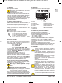 3
3
-
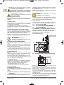 4
4
-
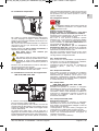 5
5
-
 6
6
-
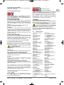 7
7
-
 8
8
-
 9
9
-
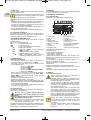 10
10
-
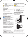 11
11
-
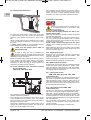 12
12
-
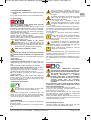 13
13
-
 14
14
-
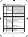 15
15
-
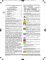 16
16
-
 17
17
-
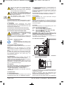 18
18
-
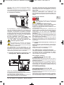 19
19
-
 20
20
-
 21
21
-
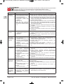 22
22
-
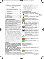 23
23
-
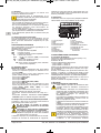 24
24
-
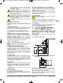 25
25
-
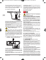 26
26
-
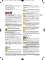 27
27
-
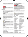 28
28
-
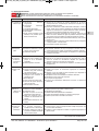 29
29
-
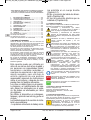 30
30
-
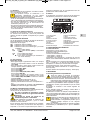 31
31
-
 32
32
-
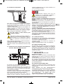 33
33
-
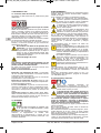 34
34
-
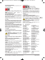 35
35
-
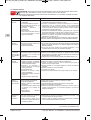 36
36
-
 37
37
-
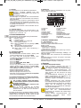 38
38
-
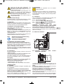 39
39
-
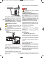 40
40
-
 41
41
-
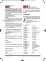 42
42
-
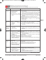 43
43
-
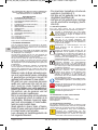 44
44
-
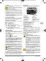 45
45
-
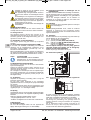 46
46
-
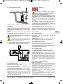 47
47
-
 48
48
-
 49
49
-
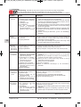 50
50
-
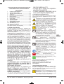 51
51
-
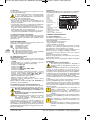 52
52
-
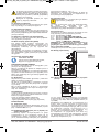 53
53
-
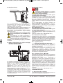 54
54
-
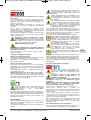 55
55
-
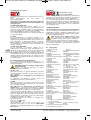 56
56
-
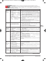 57
57
-
 58
58
-
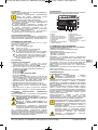 59
59
-
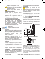 60
60
-
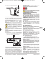 61
61
-
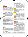 62
62
-
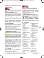 63
63
-
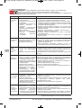 64
64
-
 65
65
-
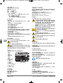 66
66
-
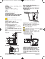 67
67
-
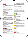 68
68
-
 69
69
-
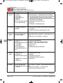 70
70
-
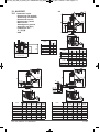 71
71
-
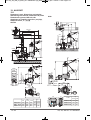 72
72
-
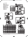 73
73
-
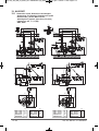 74
74
-
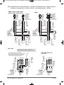 75
75
-
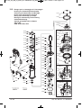 76
76
-
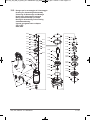 77
77
-
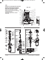 78
78
-
 79
79
-
 80
80


dans d''autres langues
- italiano: Calpeda GQG Istruzioni per l'uso
- Deutsch: Calpeda GQG Bedienungsanleitung