
KITCHEN
STORAGE ACCESSORIES
INSTALLATION GUIDE
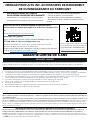
ATTENTION: Is your Storage Accessory damaged?
Need help or spare parts? For fastest service,
contact NewAge Products at 1-877-306-8930;
or suppor[email protected]om.
Do not return to the retailer.
STOP
IM-HKC.02A-01 REV 1.1

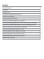
Index
Product Inspection 3
Tools Needed 3
Maintenance and Care 3
Installing the Pull out 50L bin 4
Installing the Magic Corner 6
Installing the Iron Board 8
Installing the 18”, 24”, 36” Pants Display Rack 10
Installing the 18” and 24” Closet Rod on Cabinet Walls 12
Installing the 18” and 24”Closet Rod on Cabinet Shelf 14
Installing the 18”, 24”, 36” Pull out Hamper Basket 16
Installing the Under Sink Organizer 19
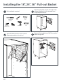
Installing the 12” and 18” Double Pull-out Basket 22
Installing the 18”, 24”, 36” Pull-out Basket 24
5 YEAR LIMITED WARRANTY 26

3
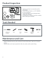
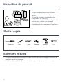
Product Inspection
• Check to see all parts are received as per the
order placed.
• Contact NewAge Products at 1-877-306-8930;
for any missing parts.
• Inspect the products for any damages before
starting the installation.
• Go through the installation instructions carefully
before starting the installation.
• Wipe and clean the accessory with a soft cloth. Do not use the scourers, abrasives or chemical
cleaners.
• Keep the slides out of water to protect the slides, thus make sure the smooth sliding.
Tools Needed
Maintenance and Care
#2 Philips Head
Screw Driver
Pencil
Cordless Drill
(Optional)
#2 Philips BitDrill Bit
3/16”
Level

4
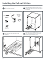
Installing the Pull out 50L bin
#2 Philips Head
Screw Driver
Pencil
M5 x 16mm
Melamine Screw
#2 Philips Bit
Cordless Drill
(optional)
Level
Drill Bit
3/16”
back
4
0.67in (17mm)
3.72in (94.5mm)3.15in (80mm)
SKU #80671, 80672
50L, 35L
Garbage Pullout Bin
Lay this template at on the interior base of the cabinet.
Tools Required:
These templates are designed
to drill the proper mounting
holes for your cabinet
accessories. These templates
are for NewAge Cabinets and
accessories only.
1 x Cordless Power Drill
1 x Pencil
1 x 3/16” Drill Bit
Note: Do not drill through
entire cabinet
1
Align the left or right edge of the template with the left
or right side of the interior cabinet based on the
preferred installation location
Ensure the arrows below are aligned with the front
edge of the cabinet and mark the specied locations
with a pencil.
Drill pilot holes into the
marked locations using an
3/16” drill bit.
2
3
4
2
2
3
3
2
2
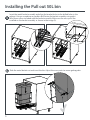
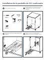
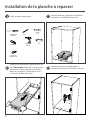
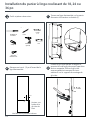
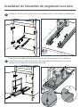
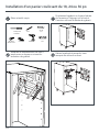
Tools and parts needed.
Place the template on the bottom of the
cabinet and align it to the front and side of
the cabinet.
Mark the drill holes layed out on the
template.
Drill holes at the marked locations using
3/16” mm drill bit while ensuring not to
drill through the bottom panel.
11
2 3

5
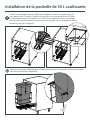
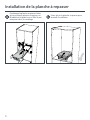
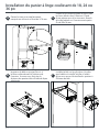
Insert the metal basket assembly and align the bracket holes to the drilled holes in the
cabinet. Using a screwdriver or cordless drill fasten the basket assembly using eight
M5x16mm screws included with the basket assembly. Make sure the cross posts are
installed on the basket assembly as shown in the image (A).
Slide the metal basket out and insert the bin. Adjust the cross posts to secure garbage bin.
1
6
Installing the Pull out 50L bin
4
A

6
Installing the Magic Corner
#2 Philips Head
Screw Driver
Pencil
M5 x 8 mm
Melamine Screw
M5 x 16mm
Melamine Screw
#2 Philips Bit
M4 x 8 mm
Melamine Screw
Cordless Drill
(optional)
Level
Drill Bit
3/16”
A
B
B
B
A
14.09in (358mm)
14.09in (319mm)
5.9in (150mm) 5.9in (150mm) 5.9in (150mm) 3.11in (79mm)
0.75in (19.5mm)
0.75in (19.5mm)
3.77in (96mm)
3.11in (79mm)
SKU #80691
Magic Corner
These templates are designed to
drill the proper mounting holes for
your cabinet accessories. These
templates are for NewAge
Cabinets and accessories only.
Lay this template at on the
interior base of the cabinet.
Tools Required:
1 x Cordless Power Drill
1 x Pencil
1 x 3/16” Drill Bit
Note: Do not drill through
entire cabinet
1
Align edge A with the left
side of the interior cabinet.
2
Ensure the arrows below,
marked B, are aligned with
the interior front edge of
the cabinet (Refer to image
C below) and mark the
specied locations with a
pencil.
3
Drill pilot holes into the
marked locations using an
3/16” drill bit.
4
Installation as shown in Cabinet: (not to scale)
Interior Front Edge
C
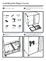
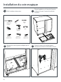
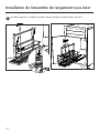
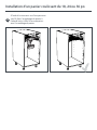
Tools and parts needed.
Place the template on the bottom of the
cabinet and align it to the front and side of
the cabinet.
Mark the drill holes layed out on the
template.
Drill holes at the marked locations using
3/16” mm drill bit while ensuring not to
drill through the bottom panel.
11
2 3
A
B
B
B
A
14.09in (358mm)
14.09in (319mm)
5.9in (150mm) 5.9in (150mm) 5.9in (150mm) 3.11in (79mm)
0.75in (19.5mm)
0.75in (19.5mm)
3.77in (96mm)
3.11in (79mm)
SKU #80691
Magic Corner
These templates are designed to
drill the proper mounting holes for
your cabinet accessories. These
templates are for NewAge
Cabinets and accessories only.
Lay this template at on the
interior base of the cabinet.
Tools Required:
1 x Cordless Power Drill
1 x Pencil
1 x 3/16” Drill Bit
Note: Do not drill through
entire cabinet
1
Align edge A with the left
side of the interior cabinet.
2
Ensure the arrows below,
marked B, are aligned with
the interior front edge of
the cabinet (Refer to image
C below) and mark the
specied locations with a
pencil.
3
Drill pilot holes into the
marked locations using an
3/16” drill bit.
4
Installation as shown in Cabinet: (not to scale)
Interior Front Edge
C

7
Installing the Magic Corner
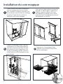
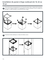
Insert the sliding base and align the
bracket holes to the drilled holes in the
cabinet. Using a screwdriver or cordless
drill fasten the basket assembly using the
eight M5x16 screws included with the
Magic corner.
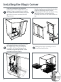
Slide the top frame and attach the handles
using two M4x8mm screws. Attach
bottom brackets (B) to the top frame using
eight M5x8 screws included with the
assembly and screw in the two handles on
top.
Insert the top frame assembly and align
the bracket holes with the holes on
the sliding base. Using a screwdriver
or cordless drill fasten the top frame
assembly using the eight M5x8 screws
included with the assembly.
Slide the top frame assembly out and
install the metal baskets.
11
2 7
5
6
4
B

8
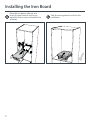
Installing the Iron Board
#2 Philips Head
Screw Driver
Pencil
M5 x 16mm
Melamine Screw
#2 Philips Bit
Cordless Drill
(optional)
Level
Drill Bit
3/16”
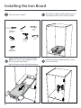
Tools and parts needed.
Place the Iron board at desired position on
the cabinet shelf. Ensure shelf is leveled
Slide the iron board out from the frame.
(Note: Use two or more people to hold
the iron board in position.)
Mark the holes on the sliding frame base.
Drill holes at the marked locations using
3/16 mm drill bit.
11
2 3

9
Place the iron board, slide out and
fasten the iron board to shelf using
eight M5x16mm screws included in the
assembly.
Slide the ironing board in to nish the
installation.
11 54
Installing the Iron Board

10
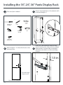
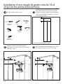
Installing the 18”, 24”, 36” Pants Display Rack
#2 Philips Head
Screw Driver
Pencil
M5 x 16mm
Melamine Screw
#2 Philips Bit
Cordless Drill
(optional)
Level
Drill Bit
3/16”
L
1.5 in
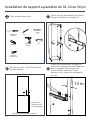
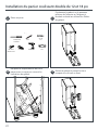
Tools and parts needed.
Draw a horizontal line on the cabinet walls
at desired height (L).
Mark a hole at 1.5 in from the front on the
horizontal line.
Insert the side mounted slide and align
the rst hole on the slide with the marked
hole position. Use the slide as template,
mark the outer holes on slide mounting
bracket.
11
2 3
L
1.5 in
L
Side view of inside panel
Desired height
of pants rack

11
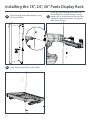
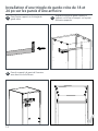
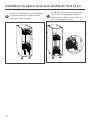
Installing the 18”, 24”, 36” Pants Display Rack
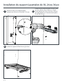
Drill holes at the marked locations using
3/16 mm drill bit.
Insert the slide and align the holes with
the drilled holes on the cabinet. Using a
power drill or screw driver fasten the side
mounting slide to the cabinet using four
M5x16mm Screws.
Insert the rack and clip it on the slides.
5
4
6

12
#2 Philips Head
Screw Driver
Pencil
Ø5 x26mm
Melamine Screws
#2 Philips Bit
Cordless Drill
(optional)
Level
Drill Bit
3/16”
X
X
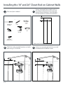
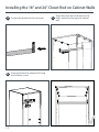
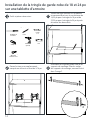
Tools and parts needed.
Draw a horizontal line on both walls of
the cabinet at distance X from top and
vertical line at distance Y from the back.
Put the bracket on wall and mark holes.
Drill holes at the marked locations on both
walls using 3/16” drill bit.
Fasten one mounting bracket to one side
of cabinet with 5x26mm screws.
1
1
2
3
Installing the 18” and 24” Closet Rod on Cabinet Walls
X
Side view of inside panel

13
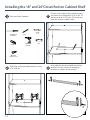
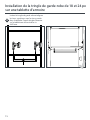
Fix the other bracket to the closet rod.
Align the closet rod and bracket to the
holes marked on the opposite cabinet
wall.
Fasten the bracket to cabinet wall using
two 5x26mm screws.
5
4
6
Installing the 18” and 24” Closet Rod on Cabinet Walls

14
Installing the 18” and 24”Closet Rod on Cabinet Shelf
#2 Philips Head
Screw Driver
Pencil
Ø4 x20mm
Melamine Screws
#2 Philips Bit
Cordless Drill
(optional)
Level
Drill Bit
3/16”
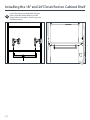
Tools and parts needed.
Draw a centre line on the shelf and mark
two holes at a distance of 16.25 in for 18”
closet rod and 22.25 in for 24” closet rod
from the centre on both sides.
Drill holes at the marked locations using
3/16” drill bit.
Assemble the closet rod and mounting
brackets. Fix the covers of mounting
brackets as shown in the image C.
11
2 3
C

15
Insert the closet rod and align the top
holes with the drilled holes on shelf.
Fasten the closet rod to shelf using two
4x20mm screws.
4
Installing the 18” and 24”Closet Rod on Cabinet Shelf

16
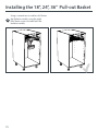
Installing the 18”, 24”, 36” Pull out Hamper Basket
#2 Philips Head
Screw Driver
Pencil
M5 x 16mm
Melamine Screw
#2 Philips Bit
Cordless Drill
(optional)
Level
Drill Bit
3/16”
L
1.5 in
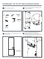
Tools and parts needed.
Draw a horizontal line on the cabinet walls
at desired height (L).
Insert the side mounted slide and align
the rst hole on the slide with the
marked hole position. Use the slide as
template mark the outer holes of the slide
mounting bracket.
1
1
3
L
Mark a hole at 1.5 in from the front on the
horizontal line.
2
1.5 in
L
Side view of inside panel
Desired height
of drawer slide

17
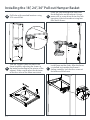
Installing the 18”, 24”, 36” Pull out Hamper Basket
Take the support frame and adjust the
frame length by adjusting the screws at
the bottom according to the interior of the
cabinet. Make sure to adjust the distance
of the four sides of the frame consistent.
Install frame on the slides. After the frame
is installed, test weather the frame is
sliding smoothly. Lock the four screws at
the bottom of the frame.
2
7
6
Drill holes at the marked locations using
3/16 mm drill bit.
Insert the slide and align the holes with
the drilled holes on the cabinet. Using a
power drill or screw driver fasten the side
mounting slide to the cabinet using four
M5x16mm Screws.
5
4

18
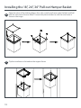
Open the velcro of the clothing bag on four sides, install wire frame under the folds and fold
back the velcro over the wire frame. Connect the plastic holders to with the wire frame as
shown in the image.
Clip the wireframe to the bottom the support frame.
8
9
Installing the 18”, 24”, 36” Pull out Hamper Basket

19
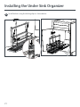
Installing the Under Sink Organizer
#2 Philips Head
Screw Driver
Pencil
M5 x 16mm
Melamine Screw
#2 Philips Bit
M4 x 6mm
Screw
Cordless Drill
(optional)
Level
Drill Bit
3/16”
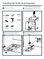
Tools and parts needed.
1
2.32in
(59mm)
1.40in
(35.5mm)
5.61in
(142.5mm)
3.05in
(77.5mm)
min 3.98in (101mm)
if installed on the left
edge
min 3.98in (101mm)
if installed on the right
edge
SKU #80690
Undersink Organizer
Lay this template
at on the interior
base of the cabinet.
Drill pilot holes
into the marked
locations using a
3/16” drill bit.
Note: Do not drill
through entire cabinet
Ensure the arrows below are aligned with the front edge of the
cabinet and mark the specied locations with a pencil.
Tools Required:
1 x
1 x Pencil
1 x 3/16” Drill Bit
Cordless
Power
Drill
1
3
4
Align the left or
right edge of this
template based on
the space allowed
inside of the
cabinet by local
plumbing.
2
2
2
2
These templates are
designed to drill the
proper mounting
holes for your cabinet
accessories. These
templates are for
NewAge Cabinets and
accessories only.
Place the template on the bottom panel
of cabinet, aligning it to desired location
using template arrows.
1
2.32in
(59mm)
1.40in
(35.5mm)
5.61in
(142.5mm)
3.05in
(77.5mm)
min 3.98in (101mm)
if installed on the left
edge
min 3.98in (101mm)
if installed on the right
edge
SKU #80690
Undersink Organizer
Lay this template
at on the interior
base of the cabinet.
Drill pilot holes
into the marked
locations using a
3/16” drill bit.
Note: Do not drill
through entire cabinet
Ensure the arrows below are aligned with the front edge of the
cabinet and mark the specied locations with a pencil.
Tools Required:
1 x
1 x Pencil
1 x 3/16” Drill Bit
Cordless
Power
Drill
1
3
4
Align the left or
right edge of this
template based on
the space allowed
inside of the
cabinet by local
plumbing.
2
2
2
2
These templates are
designed to drill the
proper mounting
holes for your cabinet
accessories. These
templates are for
NewAge Cabinets and
accessories only.
Remove the template and drill the marked
holes using a 3/16” drill bit.
Mark drill hole locations with a pencil
following template instructions.
32

20
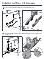
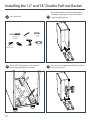
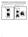
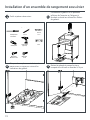
Install rails aligning with the pre marked holes using eight M5x16mm screws.
Slide the centre frame assembly onto the rails by pushing it under the clips at back of the
slides as shown in (A). Secure front portion of the frame to the rails using two M4x6mm screws
as shown in (B).
4
5
A
B
A
Installing the Under Sink Organizer
A
B
La page est en cours de chargement...
La page est en cours de chargement...
La page est en cours de chargement...
La page est en cours de chargement...
La page est en cours de chargement...
La page est en cours de chargement...
La page est en cours de chargement...
La page est en cours de chargement...
La page est en cours de chargement...
La page est en cours de chargement...
La page est en cours de chargement...
La page est en cours de chargement...
La page est en cours de chargement...
La page est en cours de chargement...
La page est en cours de chargement...
La page est en cours de chargement...
La page est en cours de chargement...
La page est en cours de chargement...
La page est en cours de chargement...
La page est en cours de chargement...
La page est en cours de chargement...
La page est en cours de chargement...
La page est en cours de chargement...
La page est en cours de chargement...
La page est en cours de chargement...
La page est en cours de chargement...
La page est en cours de chargement...
La page est en cours de chargement...
La page est en cours de chargement...
La page est en cours de chargement...
La page est en cours de chargement...
La page est en cours de chargement...
-
 1
1
-
 2
2
-
 3
3
-
 4
4
-
 5
5
-
 6
6
-
 7
7
-
 8
8
-
 9
9
-
 10
10
-
 11
11
-
 12
12
-
 13
13
-
 14
14
-
 15
15
-
 16
16
-
 17
17
-
 18
18
-
 19
19
-
 20
20
-
 21
21
-
 22
22
-
 23
23
-
 24
24
-
 25
25
-
 26
26
-
 27
27
-
 28
28
-
 29
29
-
 30
30
-
 31
31
-
 32
32
-
 33
33
-
 34
34
-
 35
35
-
 36
36
-
 37
37
-
 38
38
-
 39
39
-
 40
40
-
 41
41
-
 42
42
-
 43
43
-
 44
44
-
 45
45
-
 46
46
-
 47
47
-
 48
48
-
 49
49
-
 50
50
-
 51
51
-
 52
52


NewAge Products 80643 Guide d'installation
- Taper
- Guide d'installation
- Ce manuel convient également à
dans d''autres langues
Documents connexes
-
 NewAge Products 55975 Manuel utilisateur
-
NewAge Products 63245 Mode d'emploi
-
 NewAge Products 55972 Mode d'emploi
-
NewAge Products 56641 Manuel utilisateur
-
 NewAge Products 53255 Mode d'emploi
-
 NewAge Products 54368 Guide d'installation
-
 NewAge Products 52380 Guide d'installation
-
 NewAge Products 51604 Mode d'emploi


