Nilfisk SW5500 60 B Le manuel du propriétaire
- Taper
- Le manuel du propriétaire

SW5500
Instructions for use
LPG
09/2016 Revised 04/2018
(B)
FORM NO. 1467287000
English
Français
Español
Português
Instructions d’utilisation
Instrucciones de uso
Instruções de uso
Model No.:
9084417010


INSTRUCTIONS FOR USE ENGLISH
1467287000 - SW5500 1
09/2016
TABLE OF CONTENTS
INTRODUCTION .............................................................................................................................................................. 2
MANUAL PURPOSE AND CONTENTS .......................................................................................................................................... 2
TARGET ........................................................................................................................................................................................... 2
HOW TO KEEP THIS MANUAL ....................................................................................................................................................... 2
IDENTIFICATION DATA ................................................................................................................................................................... 2
OTHER REFERENCE MANUALS ................................................................................................................................................... 3
SPARE PARTS AND MAINTENANCE ............................................................................................................................................. 3
CHANGES AND IMPROVEMENTS ................................................................................................................................................ 3
OPERATION CAPABILITIES ........................................................................................................................................................... 3
CONVENTIONS .............................................................................................................................................................................. 3
UNPACKING/DELIVERY ................................................................................................................................................. 3
SAFETY ........................................................................................................................................................................... 3
VISIBLE SYMBOLS ON THE MACHINE ......................................................................................................................................... 4
SYMBOLS THAT APPEAR ON THIS MANUAL ............................................................................................................................... 4
GENERAL INSTRUCTIONS ............................................................................................................................................................ 4
MACHINE DESCRIPTION ............................................................................................................................................... 8
MACHINE STRUCTURE ................................................................................................................................................................. 8
CONTROL PANEL ..........................................................................................................................................................................11
ACCESSORIES/OPTIONS ............................................................................................................................................................ 12
TECHNICAL DATA ......................................................................................................................................................................... 12
WIRING DIAGRAM ........................................................................................................................................................................ 14
USE ................................................................................................................................................................................ 16
FUEL .............................................................................................................................................................................................. 16
BEFORE MACHINE START-UP .................................................................................................................................................... 17
STARTING AND STOPPING THE MACHINE ............................................................................................................................... 17
PARKING BRAKE .......................................................................................................................................................................... 18
MACHINE OPERATION ................................................................................................................................................................ 19
HOPPER DUMPING ...................................................................................................................................................................... 20
AFTER USING THE MACHINE ..................................................................................................................................................... 21
MACHINE LONG INACTIVITY ...................................................................................................................................................... 21
MAINTENANCE ............................................................................................................................................................. 21
SCHEDULED MAINTENANCE TABLE ......................................................................................................................................... 21
MULTIFUNCTION DISPLAY SERVICE SCREENS ....................................................................................................................... 23
MAIN BROOM HEIGHT CHECK AND ADJUSTMENT .................................................................................................................. 25
MAIN BROOM REPLACEMENT ................................................................................................................................................... 26
SIDE BROOM HEIGHT CHECK AND ADJUSTMENT .................................................................................................................. 27
SIDE BROOM REPLACEMENT .................................................................................................................................................... 28
PANEL DUST FILTER CLEANING AND INTEGRITY CHECK ...................................................................................................... 29
SKIRT HEIGHT AND OPERATION CHECK .................................................................................................................................. 30
DUSTGUARD™ SYSTEM WATER FILTER CLEANING (OPTIONAL) ......................................................................................... 31
HYDRAULIC SYSTEM OIL LEVEL CHECK .................................................................................................................................. 31
ENGINE OIL LEVEL CHECK AND REPLACEMENT .................................................................................................................... 32
ENGINE AIR FILTER CHECK/CLEANING .................................................................................................................................... 33
ENGINE SPARK PLUG CHECK/REPLACEMENT ........................................................................................................................ 34
BATTERY CHARGING (only for version with optional hybrid KIT installed) .................................................................................. 35
FUSE CHECK/REPLACEMENT .................................................................................................................................................... 36
SAFETY FUNCTIONS ................................................................................................................................................... 36
EMERGENCY PUSH-BUTTON ..................................................................................................................................................... 36
DRIVER’S SEAT MICROSWITCH ................................................................................................................................................. 36
ANTI-SKID SAFETY SYSTEM ...................................................................................................................................................... 36
MACHINE ANGLE SENSOR ......................................................................................................................................................... 36
HOPPER POSITION SENSOR ..................................................................................................................................................... 36
HOPPER SAFETY VALVE ............................................................................................................................................................. 36
TROUBLESHOOTING ................................................................................................................................................... 37
SCRAPPING .................................................................................................................................................................. 38

ENGLISH INSTRUCTIONS FOR USE
2SW5500 - 1467287000 09/2016
INTRODUCTION
NOTE
The numbers in brackets refer to the components shown in Machine Description chapter.
MANUAL PURPOSE AND CONTENTS
The purpose of this Manual is to provide the operator with all necessary information to use the machine properly, in a safe and
autonomous way. It contains information about technical data, safety, operation, storage, maintenance, spare parts and disposal.
Before performing any procedure on the machine, the operators and qualied technicians must read this Manual carefully. Contact
Advance in case of doubts regarding the interpretation of the instructions and for any further information.
TARGET
This Manual is intended for operators and technicians qualied to perform the machine maintenance.
The operators must not perform procedures reserved for qualied technicians. Advance will not be responsible for damages coming
from failure to follow these instructions.
HOW TO KEEP THIS MANUAL
The Instructions for Use Manual must be kept near the machine, inside an adequate case, away from liquids and other substances
that can cause damage to it.
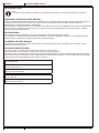
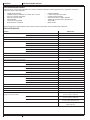
IDENTIFICATION DATA
The machine serial number and model name are marked on the plate (30).
Product code and year of production are marked on the same plate.
The engine model and serial number are shown on the engine plate (see the engine manual).
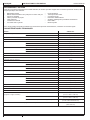
This information is useful when ordering machine and engine spare parts. Use the following table to write down the machine and
engine identication data for any further reference.
MACHINE model ...............................................................................
PRODUCT code ................................................................................
MACHINE serial number ...................................................................
ENGINE model ..................................................................................
ENGINE serial number ......................................................................

INSTRUCTIONS FOR USE ENGLISH
1467287000 - SW5500 3
09/2016
OTHER REFERENCE MANUALS
– Spare Parts List (supplied with the machine)
– Engine Manual (Honda iGX 270)
– Service Manual (that can be consulted at Advance Service Centers)
SPARE PARTS AND MAINTENANCE
All necessary operating, maintenance and repair procedures must be performed by qualied personnel or by Advance Service
Centers. Only original spare parts and accessories must be used.
Contact Advance for service or to order spare parts and accessories, specifying the machine model, product code and serial
number.
CHANGES AND IMPROVEMENTS
Advance constantly improves its products and reserves the right to make changes and improvements at its discretion without being
obliged to apply such benets to the machines that were previously sold.
Any change and/or addition of accessories must be approved and performed by Advance.
OPERATION CAPABILITIES
This sweeper has been approved to clean (sweeping and vacuuming) compact and solid oors, in commercial or industrial
environments, under safe operation conditions by a qualied operator.
CONVENTIONS
Forward, backward, front, rear, left or right are intended with reference to the operator’s position, that is to say on the driver’s seat
(3).
UNPACKING/DELIVERY
CAUTION!
To unpack the machine, carefully follow the instructions on the packing.
Upon delivery carefully check that the machine and its packing have not been damaged during transportation. In case of visible
damages, keep the packing and have it checked by the carrier that delivered it. Call the carrier immediately to ll in a damage claim.
Check that the machine is equipped with the following features:
– Technical documents:
• Sweeper Instructions for Use Manual (this document)
• Engine Manual (Honda iGX 270)
• Sweeper Spare Parts List
– No. 1 10 A fuse
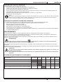
SAFETY
The following symbols indicate potentially dangerous situations. Always read this information carefully and take all necessary
precautions to safeguard people and property.
The operator’s cooperation is essential in order to prevent injury. No accident prevention program is eective without the total
cooperation of the person responsible for the machine operation. Most of the accidents that may occur in a factory, while working
or moving around, are caused by failure to comply with the simplest rules for exercising prudence. A careful and prudent operator is
the best guarantee against accidents and is essential for successful completion of any prevention program.

ENGLISH INSTRUCTIONS FOR USE
4SW5500 - 1467287000 09/2016
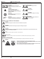
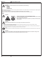
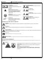
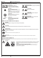
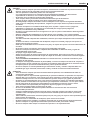
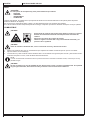
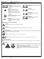
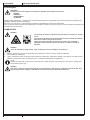
VISIBLE SYMBOLS ON THE MACHINE
WARNING!
Carefully read all the instructions
before performing any operation on the
machine.
DANGER!
Internal combustion engine.
Do not inhale exhaust gas fumes.
Carbon monoxide (CO) can cause brain
damage or death.
WARNING!
Do not wash the machine with direct or
pressurized water jets.
X
%
WARNING!
Do not use the machine on slopes with
a gradient exceeding the specications.
WARNING!
Hot parts, danger of burns.
WARNING!
Moving parts.
WARNING!
Moving parts. Danger of crushing.
WARNING!
Parts under voltage. Presence of
corrosive uids.
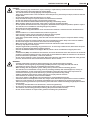
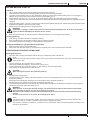
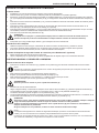
SYMBOLS THAT APPEAR ON THIS MANUAL
DANGER!
It indicates a dangerous situation with risk of death for the operator.
WARNING!
It indicates a potential risk of injury for people or damage to objects.
CAUTION!
It indicates a caution or a remark related to important or useful functions. Pay careful attention to the
paragraphs marked by this symbol.
NOTE
It indicates a remark related to important or useful functions.
CONSULTATION
It indicates the necessity to refer to the Instructions for use Manual before performing any procedure.
GENERAL INSTRUCTIONS
Specic warnings and cautions to inform about potential damages to people and machine are shown below.
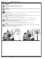
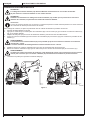
DANGER!
–Carbon monoxide (CO) can cause brain damage or death.
–The internal combustion engine of this machine can emit carbon monoxide.
–Do not inhale exhaust gas fumes.
–Only use indoors when adequate ventilation is provided, and with the help
of an assistant who can monitor the operator’s health.

INSTRUCTIONS FOR USE ENGLISH
1467287000 - SW5500 5
09/2016
DANGER!
–Before performing any maintenance, repair, cleaning or replacement procedure disconnect the batteries,
remove the ignition key and engage the parking brake.
–This machine must be used by properly trained operators only.
–Sharp turns must be made in safe conditions. Avoid abrupt turns, particularly on slopes, and turns with the
hopper lifted.
–Do not lift the hopper when the machine is on a slope.
–Keep the batteries away from sparks, ames and incandescent material.
–Do not wear jewels when working near electrical components.
–Do not work under the lifted machine without supporting it with safety stands.
–When working under the open hood, ensure that it cannot be closed by accident.
–Do not operate the machine near toxic, dangerous, ammable and/or explosive powders, liquids or vapors:
This machine is not suitable for collecting dangerous powders.
–Be careful: fuel is highly ammable.
–Do not smoke or bring naked ames in the area where the machine is refueled or where the diesel fuel is
stored.
–Refuel outdoors or in a well-ventilated area, with the engine o.
–Leave at least a space of 4 cm in the ller to allow the fuel to expand.
After refueling, check that the fuel tank cap is rmly closed.
–If any fuel is spilled while refueling, clean the tank area and allow the vapors to evaporate before starting
the engine.
–Do not let fuel come into contact with the skin; do not breathe fuel vapors. Keep out of reach of children.
–Do not tilt the engine or the machine too much to avoid fuel spillage.
–When moving the machine, the fuel tank must not be full and the fuel valve must be closed.
–Do not lay any object on the engine.
–Stop the engine before performing any procedure on it. To avoid any incidental start, disconnect the spark
plug cap or disconnect the battery negative terminal.
–See also the SAFETY RULES in the Engine Manual, which is to be considered an integral part of this
Manual.
–Lead batteries (WET) are installed on this machine, do not tilt the machine more than 30° from its horizontal
position to prevent the highly corrosive acid to leak out of the batteries. When the machine is to be tilted to
perform maintenance procedures, remove the batteries.
–Do not use the machine in case of gas leaks. Disconnect the hose and replace the LPG tank. If the gas leak
persists, disconnect the hose and contact the Advance Service Center.
WARNING!
–Carefully read all the instructions before performing any maintenance/repair procedure.
–The machine must be regularly inspected by qualied personnel, especially the LPG tank and its
connections to grant a safe use, as stated by the local laws in force.
–When working near the hydraulic system, always wear protective clothes and safety glasses.
–This machine is not intended for use by persons (including children) with reduced physical, sensory or
mental capabilities, or lack of experience and knowledge, unless they have been given supervision or
instruction concerning use of the machine by a person responsible for they safety.
Children should be supervised to ensure that they do not play with the machine.
–Close attention is necessary when used near children.
–Use only as shown in this Manual. Use only Advance’s recommended accessories.
–Check the machine carefully before each use, always check that all the components have been assembled
before use. If the machine is not perfectly assembled it can cause damages to people and properties.
–Take all necessary precautions to prevent hair, jewels and loose clothes from being caught by the machine
moving parts.
–To avoid any unauthorized use of the machine, remove the ignition key.
–Do not leave the machine unattended without being sure that it cannot move independently.
–The machine must be safely parked (considering the pressurized LPG on board).
–Do not use the machine on slopes with a gradient exceeding the specications.

ENGLISH INSTRUCTIONS FOR USE
6SW5500 - 1467287000 09/2016
WARNING!
–Do not tilt the machine more than the angle indicated on the machine itself, in order to prevent instability.
–Use only brooms supplied with the machine or those specied in the Instructions for Use Manual. Using
other brooms could reduce safety.
–This is a class A product. In a domestic environment this product may cause radio interference in which
case the user may be required to take adequate measures.
–Before using the machine, close all doors and/or covers as shown in the Instructions for Use Manual.
–Do not wash the machine with direct or pressurized water jets, or with corrosive substances.
–Use the machine only where a proper lighting is provided.
–Working lights (optional) have to be used only to enhance visibility on the oor to be cleaned, but they do
not authorize anyone to use the sweeper in dark environments.
–While using this machine, take care not to cause damage to people or objects.
–Do not bump into shelves or scaoldings, especially where there is a risk of falling objects.
–If the proper protective guard (FOPS)(optional) is not installed, do not use the machines in areas where
there is the risk of falling objects.
–Do not lean liquid containers on the machine, use the relevant can holder.
–The machine storage temperature must be +32 °F to 104 °F (0 °C to +40 °C).
–The machine working temperature must be +32 °F to 104 °F (0 °C to +40 °C).
–The humidity must be between 30 % and 95 %.
–Always protect the machine against the sun, rain and bad weather, both under operation and inactivity
condition. Store the machine indoors, in a dry place. (If applicable) This machine must be used in dry
conditions, it must not be used or kept outdoors in wet conditions.
–Do not use the machine as a means of transport, or for pushing/towing.
–The machine maximum capacity, operator’s weight not included, is 529 lb (240 kg) (the weight of waste).
–In case of re, use a powder re extinguisher, not a water one.
–Adjust the operation speed to suit the oor conditions.
–Avoid sudden stops when the machine is going downhill. Avoid sharp turns. Drive at slow speed when
going downhill.
–This machine cannot be used on roads or public streets.
–Do not tamper with the machine safety guards.
–Follow the routine maintenance procedures scrupulously.
–Do not allow any object to enter into the openings. Do not use the machine if the openings are clogged.
Always keep the openings free from dust, hairs and any other foreign material which could reduce the air
ow.
–(Only for versions equipped with DustGuard™ system). Pay attention during machine transportation
when temperature is below freezing point. The water in the tank or in the hoses could freeze and seriously
damage the machine.
–Do not remove or modify the plates axed to the machine.
–When the machine is to be pushed for service reasons (lack of fuel, etc.), the speed must not exceed 4
km/h.
–In case of machine malfunctions, ensure that these are not due to lack of maintenance. If necessary,
request assistance from the authorized personnel or from an authorized Service Center.
–If parts must be replaced, require ORIGINAL spare parts from an Authorized Dealer or Retailer.
–To ensure machine proper and safe operation, the scheduled maintenance shown in the relevant chapter of
this Manual, must be performed by the authorized personnel or by an authorized Service Center.
–The machine must be disposed of properly, because of the presence of toxic-harmful materials (batteries,
oils, etc.), which are subject to standards that require disposal in special centers (see the Scrapping
chapter).
–While the engine is running, the silencer warms up; do not touch the silencer when it is hot to avoid burns
or res.
–Running the engine with an insucient quantity of oil can seriously damage the engine. Check the oil level
with the engine o and the machine on a level surface.
–Never run the engine if the air lter is not installed, because the engine could be damaged.
–Technical service procedures on the engine must be performed by an authorized Dealer.
Only use original spare parts or parts of matching quality for the engine. Using spare parts of lower quality
can seriously damage the engine.
–See also the SAFETY RULES in the Engine Manual, which is to be considered an integral part of this
Manual.

INSTRUCTIONS FOR USE ENGLISH
1467287000 - SW5500 7
09/2016
Guide lines to bacteria control and other dangers coming from the presence of microbes in the DustGuard™
system (optional).
WARNING!
To prevent the operators and other people from developing infections caused by microbes and Legionella that
may ourish in the dust guard system, take the following precautions:
–If possible, ll the tank with cold water [< 68 °F (< 20 °C)].
–DO NOT use stagnant water to ll the tank.
–DO NOT use recycled water, undrinkable water or water that has been in contact with the soil.
–Adjust and turn the nozzles towards the oor only, from preventing possible inhaling.
–Do not store the machine outdoors or near sources of heat.
–Do not over-ll the tank. Fill the tank suciently so that it can be emptied by using the system.
–Empty the tank every 10 hours or once a week, according to the use.
–If the machine is not used for more than one week, empty the tank completely, and let it dry before storing
it.
–If the tank cannot be cleaned regularly, consider using a biocide that can kill or exert a controlling eect on
Legionella bacteria. Biocide must be chosen according to the local regulations and must be used according
to the relevant instructions and cautions, to avoid that the personnel gets aected by dangerous chemical
substances.
–If chemical products have to be used in the water tank, it is mandatory to apply the relevant information and
caution labels of the product.

ENGLISH INSTRUCTIONS FOR USE
8SW5500 - 1467287000 09/2016
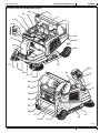
MACHINE DESCRIPTION
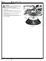
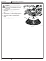
MACHINE STRUCTURE
1. Steering wheel
2. Control panel (see the following paragraph)
3. Driver’s seat with safety microswitch
4. Seat position adjusting lever
5. Accelerator pedal
6. Service brake pedal
7. Parking brake lever: press both the service brake (6) and the lever (7) to switch from the service brake to the parking brake
8. Front skirt lifting pedal
9. Main broom height adjusting knob:
• Turn it counter-clockwise to increase the broom pressure on the oor
• Turn it clockwise to decrease the broom pressure on the oor
10. Vacuum system rear hood
11. Vacuum system hood release lever
12. Hopper (empty it when it is full)
13. Right door (to be opened for performing maintenance procedures only)
14. Left door (for main broom removal)
15. Right side broom
16. Left side broom (optional)
17. Side broom guards (optional)
18. Main broom
19. Engine compartment hood
20. Can holder
21. Rear wheels
22. Front driving and steering wheel
23. Dust lter container / Dust guard system water tank (optional)
24. Panel lter
25. Dust guard system water ller neck plug (optional)
26. Dust guard system nozzles (optional)
27. Front column
28. Working lights
29. Flashing light (always on when the ignition key is turned to “I”)
30. Serial number/technical data/conformity certication plate
31. Removable right side panel
32. Removable left side panel
33. Anchoring slots for transport (not for lifting)
34. LPG cylinder
35. LPG tank fastening band
36. Engine o push-button (optional, only for hybrid version)

INSTRUCTIONS FOR USE ENGLISH
1467287000 - SW5500 9
09/2016
MACHINE STRUCTURE (Continues)
17
5
27
1
20
3
30
21
6
7
8
14
24
25
12
18
13
9
4
29
2
36
5
15
28
22
26
16
11
23
10
35
34
33
19
32
31
P100919
revised 04/2018

ENGLISH INSTRUCTIONS FOR USE
10 SW5500 - 1467287000 09/2016
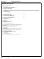
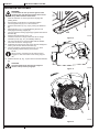
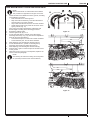
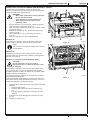
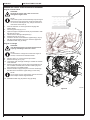
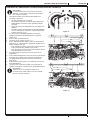
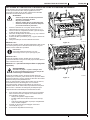
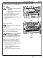
MACHINE STRUCTURE (Continues)
41. Engine compartment hood (open)
42. LPG engine
43. Hydraulic unit with tank for hopper lifting
44. Open hood safety rod
45. Alternator
46. Cooling fan
47. Batteries
47
41
44 43 42 45 46
P100920
revised 04/2018

INSTRUCTIONS FOR USE ENGLISH
1467287000 - SW5500 11
09/2016
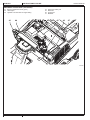
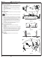
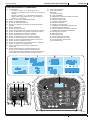
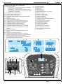
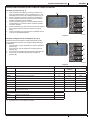
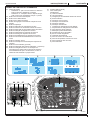
CONTROL PANEL
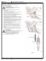
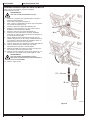
51. Ignition key:
• When turned to “0”, it turns the electrical system o and
disables all machine functions
• When turned to “II”, it starts the machine When the
machine starts, release the key, which will return to “I”
(machine ON)
52. One-Touch sweeping/vacuuming push-button
53. Right side broom push-button
54. Left side broom push-button
55. Side broom rotation speed adjustment push-buttons
56. Vacuum push-button
57. Filter shaker push-button
58. Increase maximum running speed push-button
59. Decrease maximum running speed push-button
60. Hopper lifting push-button
61. Hopper lowering push-button
62. Hopper dumping push-button
63. Hopper reset push-button
64. Reverse gear/forward gear reset push-button
65. Horn push-button
66. Hopper movement enabling push-button
67. Working light push-button (optional)
68. DustGuard™ system push-button (optional)
69. Emergency push-button. Press it in case of emergency to
stop all the machine functions.
To deactivate the emergency push-button, turn it in the
direction shown by the arrow.
70. USB socket (optional)
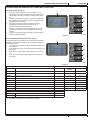
71. Multifunction display
Items displayed:
A) Working hours
B) Battery type
C) Maximum running speed setting
D) Work screen
E) Main broom activation
F) Side brooms activation
G) Vacuum activation
H) Reverse gear activation
I) Side brooms speed setting
J) Auto-shut o timer
K) Hopper opening warning
L) DustGuard™ system
M) Work light turned on
N) Main broom worn out
O) Service call
P) Fuel reserve warning
Q) Engine overheat warning
R) Engine oil pressure warning
S) Alternator warning
54
51
57
56
52
65
68 66 67
70 69
63
62
64
59
58
61
60
55 53
71
AB
H
IJK
LMNO
PQRS
D
E
C
F
G
P100921
revised 04/2018

ENGLISH INSTRUCTIONS FOR USE
12 SW5500 - 1467287000 09/2016
ACCESSORIES/OPTIONS
In addition to the standard components, the machine can be equipped with the following accessories/options, according to the
machine specic use:
– Left side broom
– Main and side brooms with harder or softer bristles
– Paper dust lter
– Non-marking skirts
– Safety belts
– Right and left armrests
– Non-marking wheels
– FOPS protective roof
– Roof cover
– Side broom guards
– DustGuard™ system
– USB™ socket
– Hybrid motor
For further information concerning the optional accessories, contact an authorized Retailer.
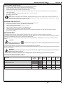
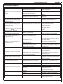
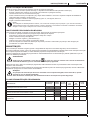
TECHNICAL DATA
Model SW5500 LPG
Cleaning width with one side broom 46.2 in (1,175 mm)
with two side brooms 59 in (1,500 mm)
Main broom size (length x diameter) 33.5 x 14.2 in (850 x 360 mm)
Side broom diameter 19.7 in (500 mm)
Hopper capacity 39.6 US gal (150 liters)
maximum liftable weight 529 lb (240 kg)
maximum lifting height 70 in (1,650 mm)
Filter cleaning system Electrical lter shaker
area 10850 ft2 (7 m2)
lter eciency 77 % @ 0,8 µm
Power 6.3 kW (8.4 hp) @ 3,600 rpm
Engine model Honda iGX 270
Fuel type LPG
Fuel tank capacity 15 Kg
Type of engine oil SAE 10W30
hopper hydraulic lifting system Arnica 46
Main broom motor power 1.7 hp (1,250 W)
speed 4,800 rpm
Side broom motor power 0.16 hp (120 W)
speed (variable) 40/155 rpm
Vacuum motor power 0.35 hp (260 W)
Drive type Electrical on the front wheel
gearmotor power 1.6 hp (1,200 W)
forward speed 6.2 mi/h (10 km/h)
reverse speed 2.8 mi/h (4.5 km/h)
Maximum gradient when working 20 %
Hopper hydraulic control unit 1.1 hp (800 W)
Filter shaker motor 2 x 0.016 hp (2 x 12 W)
Total absorbed power 3.5 hp (2.6 kW)
Dimensions
(length x width x height)
machine body 73.8 x 47.2 x 61.6 in
(1,875 x 1,200 x 1,564 mm)
machine with side brooms 73.8 x 51.2 x 61.6 in
(1,875 x 1,300 x 1,564 mm)
machine with FOPS protective roof (optional) 73.8x47.2x78.5/81.7 in
(1,875x1,200x1,995/2,075 mm)
LPG tank maximum size (length x diameter) 34.9 x 12 in
(886 x 306 mm)
revised 04/2018

INSTRUCTIONS FOR USE ENGLISH
1467287000 - SW5500 13
09/2016
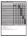
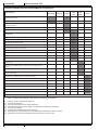
TECHNICAL DATA (Continues)
Model SW5500 LPG
Weight kerb weight 1684 lb (764 Kg)
total kerb weight (*) 1920 lb (871 Kg)
front axle kerb weight (*) 804 lb (365 Kg)
rear axle kerb weight (*) 1115 lb (506 Kg)
gross vehicle weight (GVW) 2846 lb (1,291 Kg)
Wheel specic pressure on the oor (front - rear wheels, in running conditions) (0.7 - 0.5 N/mm2)
Sound pressure level at workstation (ISO 11201, ISO 4871, EN 60335-2-72) (LpA) 79 dB(A) ± 3 dB(A)
Machine sound pressure level (ISO 3744, ISO 4871, EN 60335-2-72) (LwA) 98 dB(A)
IP protection class X3
Dust guard system water tank (optional) capacity 8.4 US gal (32 liters)
U-turn space (right - left) 91 - 93.5 in (2,310 - 2,375 mm)
Vibration level at the operator’s arms (ISO 5349-1) (**) <98.4 in/s2 (<2.5 m/s2)
Vibration level at the operator’s body (ISO 2631-1) (**) 31.5 in/s2 (0.8 m/s2)
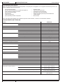
(*) With operator on board, fuel tank and hopper empty.
(**) Under normal working conditions, on a level asphalt surface.
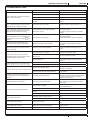
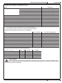
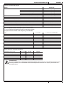
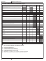
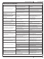
Machine Material Composition and Recyclability
Type Recyclable
percentage SW5500 LPG weight percentage
Aluminum 100 % 0.1 %
Electric motors - various 29 % 20.4 %
Ferrous materials 100 % 61.1 %
Wiring harnesses 80 % 0.0 %
Liquids 100 % 0.6 %
Plastic - non-recyclable material 0 % 0.0 %
Plastic - recyclable material 100 % 0.8 %
Polyethylene 92 % 8.1 %
Rubber 20 % 8.7 %
Cardboard - paper - wood 100 % 0.1 %
Hydraulic oil technical data
Viscosity at 104 °F (40 °C) in2/s (mm2/s) 0.07 (45) 0.05 (32)
Viscosity at 212 °F (100 °C) in2/s mm2/s (7.97) (6.40)
Viscosity index / 150 157
Flash point COC °F (°C) 419 (215) 396 (202)
Pour point °F (°C) -33 (-36) -33 (-36)
Density at 15 °C (59 °F) lb/US gal (kg/l) (0.87) (0.865)
CAUTION!
If the machine is to be used at ambient temperatures below 50 °F (+10 °C), the oil should be changed with
equivalent oil having a viscosity of 32 cSt. For temperatures below 32 °F (0 °C), use an oil with lower viscosity.

ENGLISH INSTRUCTIONS FOR USE
14 SW5500 - 1467287000 09/2016
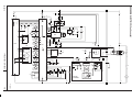
WIRING DIAGRAM
Key
A1 Main broom actuator
A2 Right side broom actuator
A3 Left side broom actuator (optional)
ALT Alternator
BAT1 12 V batteries
BAT2 12 V batteries
BZ Reverse gear buzzer
BE Flashing light
CCOIL Charging coil
CH Hybrid battery charger (optional)
D1..D3 Diode
EB1 Function electronic board
EB2 Drive system electronic board
EB3 Display board
EB4 Dashboard electronic board
EB5 Seat dashboard electronic board
EB6 Honda engine ECM
EB7 Honda engine ignition coil
ECN Encoder
ES1 Function electronic board contactor
ES2 Drive system electronic board contactor
ES3 Engine on/o relay
ES4 Engine RPM relay
ES5 Engine start relay
ES6 Fan relay
ES8 Drive system enabling relay
ES9 Horn relay
ES10 Charging system electromagnetic switch
ES11 Hybrid charging system relay
EV1 Hopper raising solenoid valve
EV2 Hopper lowering solenoid valve
EV3 Hopper solenoid valve
EV4 Fuel solenoid valve
F0 Battery fuse
F1 Function electronic board fuse
F2 Ignition key fuse
F3 Drive system fuse
F4 Alternator fuse
F5 Engine fuse
F6 Engine start fuse
F7 Fan fuse
F8 Horn fuse
HN Horn
KEY Ignition key
L1 Working light (optional)
M0 Driving wheel
M1 Vacuum system motor
M2 Filter shaker motor
M3 Hopper pump motor
M4 Main broom motor
M5 Right side broom motor
M6 Left side broom motor (optional)
M7 Engine compartment fan
MST Starter
P1 Dust guard system pump motor (optional)
R1 Accelerator pedal
R2,...4 Resistance
S1 Opened hopper sensor
S2 High hopper sensor
S3 Rotated hopper sensor
S4 Main broom wear sensor
S5 Driving wheel temperature sensor
S6 Fuel reserve sensor
S7 Oil alert sensor
S8 Diode jumper temperature sensor
SPK Engine spark plug
SW0 Emergency push-button
SW1 Driver’s seat safety microswitch
TU Trackunit (optional)
USB USB port (optional)
Color codes
BK Black
BU Blue
BN Brown
GN Green
GY Grey
OG Orange
PK Pink
RD Red
VT Violet
WH White
YE Yellow

INSTRUCTIONS FOR USE ENGLISH
1467287000 - SW5500 15
09/2016
WIRING DIAGRAM (Continues)
F2
S1 S2
P2
P1
P0
30/1
15
30
5015/54
KEY
SW0
BE
+
ES1
EB1
RD
BK
B+
F1
RD RD
BZ
J2.4
J1.5
J1.6
J2.15
J1.11
BK
J2.8
EV2
ES1
J4.1
J4.2
M5
M4
M2
M1
M6
P1
FS-
FS+
VA-
VA+
BR-
BR+
RSB-
RSB+
LSB-
LSB+
WP1
M3
PM-
PM+
EB5
J1.2
J1.3
J2.7
J1.4
WP2
R2
+
L1
J2.12
-B
J1.9
J1.10
S4
J1.19
J1.15
J1.12
J1.20
S3
EV3EV1
J2.3
J2.2
J2.1
J2.9
12V
BATT1
B+
B-
BK
BK
RD
F4
RD
S6
J2.6
J2.14
J1.8
J1.18
J1.16
ES3
M
MST
WH
F5
-
+
REG
GY
GY GY
WHGN
GY
BK WH
CCOIL
BK
ES4
S7
ES3
WHBK
YEBK LIGHTGNBK RDYE
SPK
ENGINE
CH
EB6EB7
B+
ALT
B-
BK
J1.14
ASSEMBLY
M2
A2
A1
A3
A2.4
A2.1
A1.1
A3.1
A3.4
A1.4
EB3
EB4
J1.3
J1.1
J3.4
J2
J3.2
16
J1.1
J1.4
J1.5
J1.2J3.1
ES5
ES5 F6
RD
EB2
SW1
BK
+
ES2
ES2
F3
3
M0
ENC
JD.5
JD.1
JD.4
RD
JD.6
JD.3
S5
JC.6
JC.1
JB.6
B+
BF+
B-
JB.2
W
V
U
USB
0V
JC.10(CAN_L)
JC.9 A4.3
J7.2(CAN_L)
JC.5(CAN_H) J7.1(CAN_H)
JB.8 A4.1
JD.2
F7
RD
ES6
M7
JC.4
JC.3
R1
JB.4
J1.1
J1.2
J1.3
J2.2 J2.1
GY
TU
J6.1
J6.3
J6.4
J6.5
J6.6
BN
PK
WH
YE
BU
F0
12V
BATT2
FR FR FR
FR
JC.8
S8
J1.13
D2
ES4
J2.13
J2.5
+
ES6ES10
R3
+
ES10
TU.RD
HN
0V
ES9
F8
ES9
TU.RD
RD
-
+
D1
0V
ES11
ES11
0V
COMM.4
COMM.3
BK
RD
BK
RD
BK
RD
BK
RD
BK
RD
BK
RD
BK
RD
OGBK
BK
RD
GY
BU
OGBK
BK
RD
GY
BU
GN
WH
BN
YE
VTBK
OGBK
BK
RD
BK
BU
WH
YEBK
YE
BK
BK
BK
BK
RD
BK
RD
VT
YE
YEBK
VTBK
OG
BK
PK
RDWH
BUWH
GN
YE
BU
BK
RD
RD
RD
BU
RD
RD
WH
OG OG OG
GNBK
BNBK
BUBK
RD
BNWH
VTWH
BUWH
GNWH
GN
BU
VT
BN
RD VT
BNBK
PKBK
YE
BK
OGBK OGBK
OGBK
BUBK
BK
RD
BK
RD
RDBK RDBK RDBK RDBK
GY
GYBK GYBK GYBK
RD RD
BK BK BK BK BK
RD
RD
RD
BK
WHBK
GNBK RD
RD
RD
SW2
EV4
PKBK
RDWH
D3 D4
PKBK
GN
WH
BN
SK
3
A4.4
VTVT
JC.2
0V
J1.1
J1.2
J1.3
J1.4
J1.5
P16
P17
P18
LD1
P100923

ENGLISH INSTRUCTIONS FOR USE
16 SW5500 - 1467287000 09/2016
USE
WARNING!
On some points of the machine there are some adhesive plates indicating:
–DANGER
–WARNING
–CAUTION
–CONSULTATION
While reading this Manual, the operator must pay particular attention to the symbols shown on the plates (see the Visible Symbols
On The Machine paragraph).
Do not cover these plates for any reason and immediately replace them if they are damaged.
If the machine has not been used after being transported, check that all the blocks have been removed.
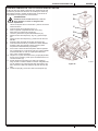
FUEL
DANGER!
–Carbon monoxide (CO) can cause brain damage or death.
–The internal combustion engine of this machine can emit carbon monoxide.
–Do not inhale exhaust gas fumes.
–Only use indoors when adequate ventilation is provided, and with the help
of an assistant.
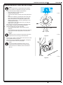
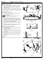
DANGER!
Before replacing the LPG tank, close the safety valve and disconnect the hose.
1. Install an LPG tank (34) having characteristics which comply with the laws in force in the country where it is used.
2. Fasten the tank with a fastening band (35).
3. Connect the hose and open the cut-o valve on the LPG tank. Always wear gloves when connecting and disconnecting the
hose. When the machine is not operating, close the LPG tank cut-o valve.
NOTE
Place the LPG tank in a proper horizontal position. Connect the hose to the tank and check that there are no gas leaks.
DANGER!
Do not use the machine in case of gas leaks. Disconnect the hose and replace the LPG tank. If the gas leak
persists, disconnect the hose and contact the Advance Service Center.

INSTRUCTIONS FOR USE ENGLISH
1467287000 - SW5500 17
09/2016
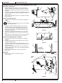
BEFORE MACHINE START-UP
Checklist
1. Have a full knowledge of the machine operating controls and their functions.
2. Insert the key (51) and start the machine (see the procedure in the following paragraph).
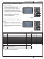
3. In the rst 2 seconds after turning on, the multifunction display (71) shows the machine working hours (71-A), the type of
batteries set (71-B) and the current maximum machine speed setting (71-C).
4. Check the fuel reserve icon (71-P); if it is lit, range will be limited. Replace the LPG tank (see previous paragraph).
5. Check the horn with switch (65), the reverse gear buzzer with switch (64) and the working light switch (67, optional) for proper
operation.
6. Check the parking brake (7 and 6). The brake must hold its (locked parked) setting rmly without easily being released (report
all defects immediately to Advance Service Center).
7. Check the service brake pedal (6) for proper operation.
WARNING!
If the pedal is “spongy” or fades under pressure without an ecient braking force, do not drive the machine
(report all defects immediately to Advance Service Center).
8. Make sure that there are no open doors/hoods and that the machine is in normal operating conditions.
Cleaning planning
1. Arrange long runs with a minimum of stopping or starting.
2. Allow a small amount of broom path overlap to ensure complete coverage.
3. Avoid making sharp turns, bumping or scraping the side of the machine.
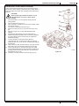
Filling the DustGuard™ system water tank (optional)
1. Remove the plug (25) to reach the ller neck.
2. Fill the tank (24) with clean water. Do not ll the tank completely, leave a few centimeters from the edge.
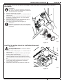
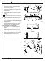
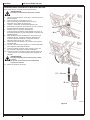
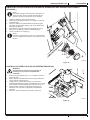
STARTING AND STOPPING THE MACHINE
Starting the machine
1. Sit on the driver’s seat (3) and adjust it with the lever (4) to allow easy reach of all controls.
NOTE
The driver’s seat (3) is equipped with a safety sensor, which allows the machine to be driven only when the operator is
on the driver’s seat.
2. Turn the ignition key (51) clockwise to the “I” position.
3. Wait for the multifunction display to show the work screen (71-D).
4. Turn the ignition key (51) to the start position “II”, then release it when the engine starts.
5. After starting, let the engine idle for a few seconds.
CAUTION!
When starting do not press the accelerator pedal (5).
6. Disengage the parking brake.
7. Drive the machine to the working area, maneuvering it by turning the steering wheel with your hands (1) and pressing the
accelerator pedal (5).
The speed can be adjusted by applying more or less pressure to the accelerator pedal (5).
The maximum running speed can be set with push-buttons (58) and (59).
8. The forward/reverse direction is selected with the relevant push-button (64) on the dashboard. Activation of reverse gear is
indicated by the buzzer and on the display (71-H).
WARNING!
When steering, avoid abrupt direction changes, pay careful attention and drive the machine at slow speed,
especially when the hopper is full or when operating on inclines.
Drive the machine slowly on inclines. Use the brake pedal (6) to control machine speed while descending
inclines.
Do not turn the machine on an incline; drive straight up or down.
NOTE
The machine has an anti-skid safety system, which where necessary reduces speed when steering and when the
machine is driving on a camber, regardless of the pressure applied to the pedal.
This reduction in speed is therefore not a malfunction but a characteristic which increases the stability and safety of the
machine in all conditions.

ENGLISH INSTRUCTIONS FOR USE
18 SW5500 - 1467287000 09/2016
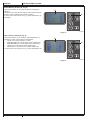
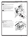
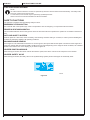
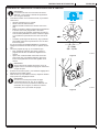
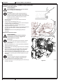
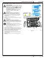
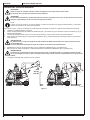
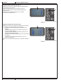
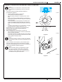
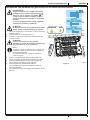
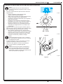
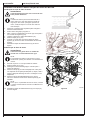
Hybrid motor (optional)
1. Perform steps 1 to 3 of the machine start-up paragraph.
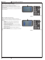
2. Ignition of the engine is not necessary while the batteries retain a sucient level of charge.
3. Check the battery charge while working. While at least one segment of the battery icon
(A, Fig. 1) is lit and not ashing on the multifunction display (71), the machine can be used
with the engine o. When the battery icon (A) has only one ashing segment remaining ,
it is advisable to start the engine, or else to recharge the batteries using the on-board battery
charger (see procedure in the Maintenance chapter).
4. To start using the machine again with the engine o, press the push-button (36) and hold it
down until the engine turns o.
5. When the multifunction display shows screen (B), a complete battery charging cycle must be
performed using the on-board battery charger. Complete the job in progress before taking the
machine to the area for charging its batteries.
6. Perform a complete charging cycle before using the machine again (see procedure in the
Maintenance chapter).
A
B
P100924
Figure 1
Stopping the machine
1. To stop the machine, release the accelerator pedal (5).
2. To stop the machine quickly, also press the service brake pedal (6).
WARNING!
The machine regulates its speed in proportion to the pressure on the accelerator pedal, accelerating and
decelerating as a result. In some particular working and environmental conditions (e.g. steep descents), the
automatic deceleration may deactivate itself to protect the system. For this reason, always use the service brake
(6) to be sure of the machine’s stopping distance.
3. In case of emergency, press the emergency push-button (69) to immediately stop the machine.
To deactivate the emergency push-button (69), turn it clockwise.
WARNING!
The emergency push-button (69) also deactivates the machine’s automatic deceleration system; if operated
while moving, use the service brake (6) to stop the machine.
4. Turn the ignition key (51) to “0” and remove it.
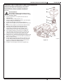
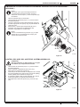
PARKING BRAKE
1. Engage the parking brake by pressing the pedal (6) and engaging the lever (7).
2. Disengage the parking brake by pressing and releasing the pedal (6).
WARNING!
Before performing any maintenance, repair, cleaning or replacement procedure engage the parking brake.
Engage the parking brake when parking the machine on a slope.
WARNING!
Before leaving the machine unattained, be sure that the parking brake can stop the machine with a large safety
margin.
WARNING!
When using the machine on slopes, respect the maximum gradient values marked on the machine itself (see
technical characteristics table).
La page est en cours de chargement...
La page est en cours de chargement...
La page est en cours de chargement...
La page est en cours de chargement...
La page est en cours de chargement...
La page est en cours de chargement...
La page est en cours de chargement...
La page est en cours de chargement...
La page est en cours de chargement...
La page est en cours de chargement...
La page est en cours de chargement...
La page est en cours de chargement...
La page est en cours de chargement...
La page est en cours de chargement...
La page est en cours de chargement...
La page est en cours de chargement...
La page est en cours de chargement...
La page est en cours de chargement...
La page est en cours de chargement...
La page est en cours de chargement...
La page est en cours de chargement...
La page est en cours de chargement...
La page est en cours de chargement...
La page est en cours de chargement...
La page est en cours de chargement...
La page est en cours de chargement...
La page est en cours de chargement...
La page est en cours de chargement...
La page est en cours de chargement...
La page est en cours de chargement...
La page est en cours de chargement...
La page est en cours de chargement...
La page est en cours de chargement...
La page est en cours de chargement...
La page est en cours de chargement...
La page est en cours de chargement...
La page est en cours de chargement...
La page est en cours de chargement...
La page est en cours de chargement...
La page est en cours de chargement...
La page est en cours de chargement...
La page est en cours de chargement...
La page est en cours de chargement...
La page est en cours de chargement...
La page est en cours de chargement...
La page est en cours de chargement...
La page est en cours de chargement...
La page est en cours de chargement...
La page est en cours de chargement...
La page est en cours de chargement...
La page est en cours de chargement...
La page est en cours de chargement...
La page est en cours de chargement...
La page est en cours de chargement...
La page est en cours de chargement...
La page est en cours de chargement...
La page est en cours de chargement...
La page est en cours de chargement...
La page est en cours de chargement...
La page est en cours de chargement...
La page est en cours de chargement...
La page est en cours de chargement...
La page est en cours de chargement...
La page est en cours de chargement...
La page est en cours de chargement...
La page est en cours de chargement...
La page est en cours de chargement...
La page est en cours de chargement...
La page est en cours de chargement...
La page est en cours de chargement...
La page est en cours de chargement...
La page est en cours de chargement...
La page est en cours de chargement...
La page est en cours de chargement...
La page est en cours de chargement...
La page est en cours de chargement...
La page est en cours de chargement...
La page est en cours de chargement...
La page est en cours de chargement...
La page est en cours de chargement...
La page est en cours de chargement...
La page est en cours de chargement...
La page est en cours de chargement...
La page est en cours de chargement...
La page est en cours de chargement...
La page est en cours de chargement...
La page est en cours de chargement...
La page est en cours de chargement...
La page est en cours de chargement...
La page est en cours de chargement...
La page est en cours de chargement...
La page est en cours de chargement...
La page est en cours de chargement...
La page est en cours de chargement...
La page est en cours de chargement...
La page est en cours de chargement...
La page est en cours de chargement...
La page est en cours de chargement...
La page est en cours de chargement...
La page est en cours de chargement...
La page est en cours de chargement...
La page est en cours de chargement...
La page est en cours de chargement...
La page est en cours de chargement...
La page est en cours de chargement...
La page est en cours de chargement...
La page est en cours de chargement...
La page est en cours de chargement...
La page est en cours de chargement...
La page est en cours de chargement...
La page est en cours de chargement...
La page est en cours de chargement...
La page est en cours de chargement...
La page est en cours de chargement...
La page est en cours de chargement...
La page est en cours de chargement...
La page est en cours de chargement...
La page est en cours de chargement...
La page est en cours de chargement...
La page est en cours de chargement...
La page est en cours de chargement...
La page est en cours de chargement...
La page est en cours de chargement...
La page est en cours de chargement...
La page est en cours de chargement...
La page est en cours de chargement...
La page est en cours de chargement...
La page est en cours de chargement...
La page est en cours de chargement...
La page est en cours de chargement...
La page est en cours de chargement...
La page est en cours de chargement...
La page est en cours de chargement...
La page est en cours de chargement...
La page est en cours de chargement...
La page est en cours de chargement...
-
 1
1
-
 2
2
-
 3
3
-
 4
4
-
 5
5
-
 6
6
-
 7
7
-
 8
8
-
 9
9
-
 10
10
-
 11
11
-
 12
12
-
 13
13
-
 14
14
-
 15
15
-
 16
16
-
 17
17
-
 18
18
-
 19
19
-
 20
20
-
 21
21
-
 22
22
-
 23
23
-
 24
24
-
 25
25
-
 26
26
-
 27
27
-
 28
28
-
 29
29
-
 30
30
-
 31
31
-
 32
32
-
 33
33
-
 34
34
-
 35
35
-
 36
36
-
 37
37
-
 38
38
-
 39
39
-
 40
40
-
 41
41
-
 42
42
-
 43
43
-
 44
44
-
 45
45
-
 46
46
-
 47
47
-
 48
48
-
 49
49
-
 50
50
-
 51
51
-
 52
52
-
 53
53
-
 54
54
-
 55
55
-
 56
56
-
 57
57
-
 58
58
-
 59
59
-
 60
60
-
 61
61
-
 62
62
-
 63
63
-
 64
64
-
 65
65
-
 66
66
-
 67
67
-
 68
68
-
 69
69
-
 70
70
-
 71
71
-
 72
72
-
 73
73
-
 74
74
-
 75
75
-
 76
76
-
 77
77
-
 78
78
-
 79
79
-
 80
80
-
 81
81
-
 82
82
-
 83
83
-
 84
84
-
 85
85
-
 86
86
-
 87
87
-
 88
88
-
 89
89
-
 90
90
-
 91
91
-
 92
92
-
 93
93
-
 94
94
-
 95
95
-
 96
96
-
 97
97
-
 98
98
-
 99
99
-
 100
100
-
 101
101
-
 102
102
-
 103
103
-
 104
104
-
 105
105
-
 106
106
-
 107
107
-
 108
108
-
 109
109
-
 110
110
-
 111
111
-
 112
112
-
 113
113
-
 114
114
-
 115
115
-
 116
116
-
 117
117
-
 118
118
-
 119
119
-
 120
120
-
 121
121
-
 122
122
-
 123
123
-
 124
124
-
 125
125
-
 126
126
-
 127
127
-
 128
128
-
 129
129
-
 130
130
-
 131
131
-
 132
132
-
 133
133
-
 134
134
-
 135
135
-
 136
136
-
 137
137
-
 138
138
-
 139
139
-
 140
140
-
 141
141
-
 142
142
-
 143
143
-
 144
144
-
 145
145
-
 146
146
-
 147
147
-
 148
148
-
 149
149
-
 150
150
-
 151
151
-
 152
152
-
 153
153
-
 154
154
-
 155
155
-
 156
156


Nilfisk SW5500 60 B Le manuel du propriétaire
- Taper
- Le manuel du propriétaire
dans d''autres langues
- English: Nilfisk SW5500 60 B Owner's manual
- español: Nilfisk SW5500 60 B El manual del propietario
- português: Nilfisk SW5500 60 B Manual do proprietário