Bosch HBL8742UC Guide d'installation
- Catégorie
- Fours
- Taper
- Guide d'installation
Ce manuel convient également à

Installation Manual
Built-in Combination Ovens
HSLP751UC, HBL57M52UC, HBL8752UC, HBLP752UC,
HBL87M52UC, HBL8742UC

2
Table of Contents
Installation instructions
Safety Definitions .......................................................... 2
IMPORTANT SAFETY INSTRUCTIONS ........................ 3
Appliance Handling Safety ................................................. 3
Safety Codes and Standards ............................................. 3
Electric Safety ....................................................................... 3
Related Equipment Safety .................................................. 4
Bosch Combination Ovens ........................................... 5
Before you Begin ........................................................... 5
Tools and Parts Needed ..................................................... 5
Power Requirements and Grounding ............................... 5
For Best Installation ............................................................. 5
Checklist ................................................................................ 6
Cabinet Dimension Requirements ............................... 6
Combination Oven and Speed Oven or Steam
Convection Oven 30” Traditional Installation .................. 7
Combination Oven and Speed Oven or Steam
Convection Oven 30” Flush Mount Installation .............. 7
Removing Packaging .................................................... 8
Packaging Bracket Removal-Left and Right Sides ........ 8
Preparing Ovens ................................................................... 8
Installation ...................................................................... 8
Pre-Assembly of the Combination Oven .......................... 8
Parts Provided ....................................................................... 8
Installation with the Speed Oven or Microwave ............. 9
Installation with the Steam Convection Oven .............. 10
Connecting the Speed Oven or Steam Convection
Oven Electrical Conduit to the Lower Oven ................. 11
Microwave Models ........................................................... 12
Electrical Installation of Combination
Oven-Grounding Instructions .................................... 13
Electrical Connection to Main Power Supply ............... 13
Four-wire Connection ....................................................... 13
Three-wire Connection ..................................................... 13
Installing Combination Oven into Wall Cabinet ....... 14
Remove Lower Oven Door Prior to Installation ........... 14
Correctly Lifting the Combination Oven ........................ 15
Lifting Recommendations ................................................ 15
Placing Combination Oven Into Cabinet Opening ...... 16
Installing the Oven into the Cabinet .............................. 16
Re-Install the Lower Oven Door ..................................... 16
Before Calling Service ...................................................... 16
Rating Label ....................................................................... 17
Lower Oven Rating Label ................................................ 17
Steam Convection Oven Rating Label .......................... 17
Speed Oven and Microwave Rating Label .................. 17
Safety Definitions
9 WARNING
This indicates that death or serious injuries may
occur as a result of non-observance of this warning.
9 CAUTION
This indicates that minor or moderate injuries may
occur as a result of non-observance of this warning.
NOTICE: This indicates that damage to the appliance or
property may occur as a result of non-compliance with
this advisory.
Note: This alerts you to important information and/or
tips.
4XHVWLRQV"
ZZZERVFKKRPHFRPXV
:HORRNIRUZDUGWRKHDULQJIURP\RX
7KLV%RVFK$SSOLDQFHLVPDGHE\
%6++RPH$SSOLDQFHV&RUSRUDWLRQ
0DLQ6WUHHW6XLWH
,UYLQH&$

3
9 IMPORTANT SAFETY INSTRUCTIONS
READ AND SAVE THESE INSTRUCTIONS
IMPORTANT SAFETY INS READ AND SAVE THESE INSTRUCTIONS
IMPORTANT: SAVE THESE INSTRUCTIONS FOR THE
LOCAL ELECTRICAL INSPECTOR’S USE.
INSTALLER: LEAVE THESE INSTALLATION
INSTRUCTIONS WITH THE UNIT FOR THE OWNER.
OWNER: PLEASE RETAIN THESE INSTRUCTIONS FOR
FUTURE REFERENCE.
WARNING
When properly cared for, your new appliance has been
designed to be safe and reliable. Read all instructions
carefully before use. These precautions will reduce the
risk of burns, electric shock, fire and injury to persons.
When using kitchen appliances, basic safety precautions
must be followed including those in the following pages.
WARNING
Do not repair, replace or remove any part of the
appliance unless specifically recommended in the
manuals. Improper installation, service or maintenance
can cause injury or property damage. Refer to this
manual for guidance. All other servicing should be done
by an authorized servicer.
Appliance Handling Safety
CAUTION
Safety Codes and Standards
This appliance complies with the latest version of one or
more of the following standards:
▯ UL 858, Household Electric Ranges
▯ UL 923, Microwave Cooking Appliances
▯ UL 507, The Standard for the Safety of Electric Fans
▯ CAN/CSA-C22.2 No. 113-M1984 Fans and Ventilators
It is the responsibility of the owner and the installer to
determine if additional requirements and/or standards
apply to specific installations.
Electric Safety
WARNING
Before you plug in an electrical cord or turn on power
supply, make sure all controls are in the OFF position.
Do not let cord hang over edge of table or counter or
touch hot surfaces.
Always attach plug to appliance first, then plug cord into
wall outlet. To disconnect, turn any control to “off”, then
remove plug from wall outlet.
Do not operate any appliance with a damaged cord or
plug or after the appliance malfunctions or has been
damaged in any manner. It is unsafe to operate any
appliance with a damaged power cord or plug. If the
appliance has been damaged or malfunctions, safely
disconnect the appliance from the power supply, then
immediately contact an authorized servicer to inspect the
product.
To protect against electrical shock, do not immerse cord,
plugs or other electrical parts in water or other liquid.
For appliances equipped with a cord and plug, do not
cut or remove the ground prong. It must be plugged in to
a matching grounding type receptacle to avoid electrical
shock. If there is any doubt as to whether the wall
receptacle is properly grounded, the customer should
have it checked by a qualified electrician. DO NOT use
an adaptor or extension cord.
If required by the National Electrical Code (or Canadian
Electrical Code), this appliance must be installed on a
separate branch circuit.
Installer-show the owner the location of the circuit
breaker or fuse. Mark it for easy reference.
WARNING
Before installing, turn power OFF at the service panel.
Lock service panel to prevent power from being turned
ON accidentally.
Refer to Rating Label for more information. See Rating
Label section for rating label location.
Be sure your appliance is properly installed and
grounded by a authorized technician. Installation,
electrical connections and grounding must comply with
all applicable codes.
▯ Unit is heavy and requires at least two people
or proper equipment to move.
▯ Do not lift appliance by door handle.
▯ Hidden surfaces may have sharp edges. Use
caution when reaching behind or under
appliance.

9 IMPORTANT SAFETY INSTRUCTIONS
READ AND SAVE THESE INSTRUCTIONS
4
Related Equipment Safety
Remove all tape and packaging before using the
appliance. Discard or recycle packaging materials
according to local codes after unpacking the appliance.
Never modify or alter the construction of the appliance.
For example, do not remove panels or covers.
CAUTION
For units with glass panels, use care when handling
glass to avoid breaking. Broken glass could cause a
laceration type injury.
State of California Proposition 65 Warnings
WARNING
This product contains chemicals known to the State of
California to cause cancer, birth defects or other
reproductive harm.
IMPORTANT SAFETY NOTICE: The California Safe
Drinking and Toxic Enforcement Act requires the
Governor of California to publish a list of substances
known to the state to cause cancer, birth defects or other
reproductive harm, and requires businesses to warn
customers of potential exposure to such substances.
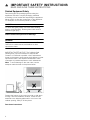
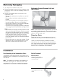
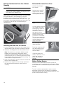
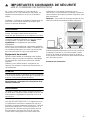
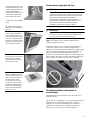
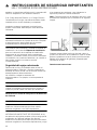
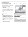
Note: To avoid damage to the oven vent, use the
transport method shown in the picture below.
Support the bottom of the oven from side to side when
moving it into the installation location. Leave the unit
attached to the shipping pallet until it is in front of the
cabinet opening, ready to lift into place.
Save these instructions.

5
Bosch Combination Ovens
The HSLP751UC, HBL57M52UC, HBL87M52UC,
HBL8752UC, and HBLP752UC Bosch combination
ovens are sold as sets, each of which includes two built-
in oven components: a traditional wall oven (lower oven)
and an upper oven that is either a built-in speed oven, a
steam convection oven or a microwave.
▯ For ease of installation and improved alignment, the
oven components are assembled together in the
customer’s home rather than at the factory.
▯ Each of the components are packed in separate
boxes, which are strapped together prior to shipping.
▯ The combination ovens listed here are approved for
use in a single cutout, using single power connection.
▯ Each traditional oven component is designed with an
oven-mounted junction box on top, which is used for
connecting the upper oven power cable.
▯ The hardware required for mounting the speed oven or
steam convection oven on top of the traditional oven
will be found inside the traditional oven box.
▯ Each of the oven components has its own rating label,
the component model number, FD number, etc.
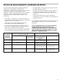
The following table identifies each of the Bosch
combination oven SKUs and its two built-in components.
Only the Bosch combination oven components in the
configurations listed in the table below are agency-
approved for use in a single cutout, using single power
connection. Other models cannot be substituted.
Before you Begin
Tools and Parts Needed
▯ Phillips-head screwdriver
▯ Star-head screwdriver (T20)
▯ Measuring tape
▯ Drill with bit (1/8”)
▯ Gloves
▯ Utility Knife
Power Requirements and Grounding
The outlet must be properly grounded in accordance with
all applicable codes.
For Best Installation
The oven can be difficult for two people to handle during
installation. It is recommended that three or more people
be available to assist with lifting the unit in to place.
Removal of the lower oven door (to reduce the unit
weight and to provide necessary gripping points) can be
cumbersome unless the detailed door removal
instructions are followed carefully. Do not attempt to
remove the speed oven door or steam convection oven
door.
Please take time to read and follow the instructions
provided for an improved installation experience.
Combination
Oven
SKU/Model
BOSCH Combination Oven Components Reference
Traditional Oven Speed Oven or
Microwave
Built-In Oven/Micro-
wave Combination
Microwave Type
HBL57M52UC HBL5451UC HMB50152UC 500 Series Combi Oven
& MW
Solo MW, 120V, 15 Amp
HBL87M52UC HBL8451UC HMB50152UC 800 Series Combi Oven
& MW
Solo MW, 120V, 15 Amp
HBL8752UC HBL8451UC HMC80252UC 800 Series Oven +
240V Speed MW
Speed MW w/LCD,
240V, 20 Amp
HBLP752UC HBLP451UC HMCP0252UC Benchmark Oven +
240V Speed MW
Speed MW w/TFT,
240V, 20 Amp

6
Checklist
Use this checklist to verify that you have completed each
step of the installation process. This can help you avoid
mistakes.
▯ Before installing the oven, be sure to verify the cabinet
dimensions are correct and the required electrical
connections are present.
▯ Refer to additional information in this manual
regarding Safety, Cabinet Dimensions, Removing
Packaging, Electrical Installation, Testing the
Installation and Customer Service.
▯ Remove the lower oven door to reduce the unit weight
and to provide access to gripping points for lifting. See
“Remove Lower Oven Door Prior to Installation”
information.
▯ Move the oven units into place in front of the cabinet
opening, leaving the bottom packaging on the units to
avoid damaging flooring.
▯ Remove the Star-head screws (T-20 size using Star-
head screwdriver) holding the speed microwave oven
or steam convection oven to the base of its carton.
▯ Assemble the two units of the combination oven. See
“Pre-Assembly of the Combination Oven”.
▯ Connect the power cable from the lower oven to the
junction box in the cabinet.
▯ Remove the Star-head screws (T-20 size using Star-
head screwdriver) holding the lower oven to the base
of its carton.
▯ Team-lift the unit directly into the cabinet cutout taking
care not to pinch fingers, scratch arms or hands.
▯ Slide the unit all the way in to place.
▯ Fasten the combination unit to the cabinetry opening
with the screws supplied (using Philips screwdriver).
▯ Reinstall the oven door removed in Step 3 above.
▯ Consult the complete installation instructions and
follow the remainder of the procedures listed,
including performing operation test.
▯ INSTALLER- Leave the literature pack and the
accessories with the customer.
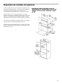
Cabinet Dimension Requirements
It is good practice, when an oven is installed at the end
of a cabinet run, adjacent to a perpendicular wall, or
cabinet door, to allow at least 1/4” (6.4 mm) space
between the side of the oven and the wall/door.
For oven support, install 2x4s extending front to back
flush with the bottom and the sides of the opening. The
supporting base must be well secured to the floor/
cabinet and level.
Junction boxes can be located anywhere within reach of
the oven’s power cable.
The cabinet base must be flat and capable of supporting
the weight of the combination oven up to 429 lbs. (195
kg).

7
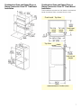
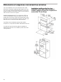
Combination Oven and Speed Oven or
Steam Convection Oven 30” Traditional
Installation
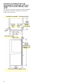
Combination Oven and Speed Oven or
Steam Convection Oven 30” Flush Mount
Installation
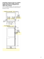
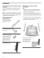
Flush installation requires two side cleats to be attached
inside the cabinet frame, recessed from the front.
)OXVK,QVWDOO7RS9LHZ
UHYHDO
FOHDWV
UHYHDO
FOHDWV
IOXVKLQVHW
GHSWK
UHYHDO
FOHDWV
7RS9LHZ
IOXVKFXWRXW
KHLJKW
PHDVXUHPHQWVLQLQFKHVPP

8
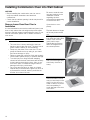
Removing Packaging
1.
Cut straps on the outside of the boxes.
2.
Remove the upper boxed unit of the combination oven
and place on floor so that both shipping cartons can
be opened.
3.
Perform the following steps on both units of the
combination oven.
▯ Remove the cardboard box by lifting it up and off
the unit
▯ Remove all top and side cardboard and foam
braces.
▯ Place the unit (leaving it on the shipping base) in
front of the cabinet where it is to be installed.
▯ Remove all accessories, racks, packing materials
and literature from the oven cavities.
▯ Unscrew unit from packaging brackets as shown in
“Packaging Bracket Removal-Left and Right Sides”.
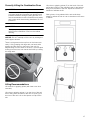
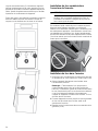
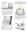
Notes
▯ The screws near the base mounting bracket of each
unit are all Star-head (T-20 size). Only the one screw
that goes through the slotted hole in the mounting
bracket on the left and right sides of the unit needs
to be removed in order to lift the unit from the
mounting base. The screw circled in the image
below and marked as (A) is the screw that needs to
be removed.
▯ Remove one screw only from each bracket. This will
release the oven from the shipping base. Do not
remove any additional screws from the oven.
Packaging Bracket Removal-Left and
Right Sides
Note: Actual bracket varies in appearance. The bracket
remains in the packaging base. The unit should stay on
the packaging base until ready to be lifted into cabinet
cutout or onto the lower oven.
Preparing Ovens
Place ovens in front of the cabinet where it is to be
installed so that they are in line with the cabinet cutout.
Check to be sure all packing materials have been
removed from the unit. Also remove the accessories,
oven racks, literature pack and any shipping materials
from inside the oven cavity. Check both ovens for a
double oven or combination oven installation.
Installation
Pre-Assembly of the Combination Oven
Combination ovens require the two components to be
assembled prior to installing the combination unit into the
wall cabinet.
Note: The installation procedures differ between the
microwave, speed oven and steam convection oven
combination units. The parts contained in the square
tube parts box are common to all three installations.
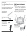
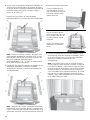
Parts Provided
Parts Provided
Universal connector
bracket (2)--in parts box
on top of oven
Screws (16)--in red bag
inside parts box on top of
oven.

9
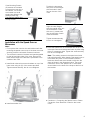
Installation with the Speed Oven or
Microwave
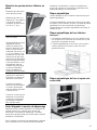
Notes
▯ Do not place the oven into the wall cabinet until after
mounting the speed oven on top of the lower oven and
securing it with the universal connector brackets.
▯ The universal connector brackets are interchangeable
for the left and right sides of the oven. Be sure the
taller vertical edge of the bracket is positioned to the
outside of the oven.
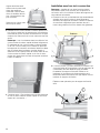
1.
Install both universal connector brackets on top of the
lower oven using six (6) of the screws provided.
Tighten screws securely, but do not overtighten.
2.
Install decorative trim.
3.
Place the speed oven or microwave unit on top of the
universal connector brackets and fasten in place using
three (3) screws per side. Tighten the screw securely,
but do not overtighten.
Note: The existing screws in the speed oven base
help with alignment. When lowering the speed oven or
microwave into place on the universal connector
brackets, allow these screw heads to slide into the
slots as shown in the illustration below. The screw
nearest the front of the speed oven or microwave
should slide into the base of the slope at the front of
the bracket.
4.
Continue to “Connecting the Speed Oven or Steam
Convection Oven Electrical Conduit to the Lower
Oven”.
Oven Mounting Screws
(8)--screws are included
to secure the oven trim to
the cabinet. The screws
are located in a small
plastic bag affixed to the
literature pack bag.
Trim Piece--in plastic bag
on top of oven.
Position the decorative
trim piece so the flanges
with the holes in them
face to the rear of the
oven.
Align the outer flanges
with the outside of the uni-
versal brackets. Fasten
with one (1) screw each
into the end hole of each
universal bracket.
Tighten screws securely,
but do not overtighten.

10
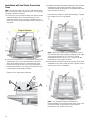
Installation with the Steam Convection
Oven
Note: Do not place the oven into the wall cabinet until
after mounting the steam convection oven on it using the
universal connector brackets.
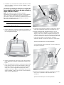
1.
Remove the six (6) screws holding the combo service
slide assemblies ((A) in illustration below) to the
support brackets. Use a magnetic screwdriver bit to
reach the screws through the large holes in the tops of
the slides.
2.
The screw in position (A) in image below (nearest the
inside edge, near control panel) must be moved to
allow the universal bracket to be positioned there.
Remove the inside screw (A) from the left support
bracket and reinsert it into the third hole (B) from the
outside edge of the support bracket.
Repeat for the right support bracket.
3.
Reattach the slide assemblies using the holes near the
inside edge of the support bracket. Align the slide
assembly parallel to the edge of the bracket and insert
the first screw in hole (C).
Insert all three screws for each slide assembly. Tighten
the screws but do not overtighten.
Note: When the correct holes are used, the front of
the slide assembly will extend just past the front edge
of the support bracket 3/16” (5mm). The slide
assembly will also be about 1/2” (12mm) from the
inside edge of the support bracket.
4.
Install the two universal connector brackets to the slide
assemblies using the screws provided. Tighten screws
securely, but do not overtighten.
Note: The universal connector brackets are
interchangeable for the left and right sides of the oven.
Be sure the taller vertical edge of the bracket is
positioned to the outside of the oven.
6XSSRUW%UDFNHWV

11
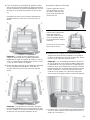
5.
Install the decorative trim.
6.
Place the steam convection oven unit on top of the
universal connector brackets and fasten in place using
two (2) screws per side. Tighten the screws securely,
but do not overtighten.
Note: The existing screws in the steam convection
oven base help with alignment. When lowering the
steam convection oven into place on the universal
connector brackets, allow these screw heads to slide
into the slots as shown in the illustration below. The
screw nearest the front of the steam convection oven
should slide into the base of the slope at the front of
the bracket.
7.
Continue to “Connecting the Speed Oven or Steam
Convection Oven Electrical Conduit to the Lower
Oven”.
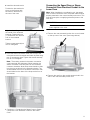
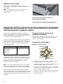
Connecting the Speed Oven or Steam
Convection Oven Electrical Conduit to the
Lower Oven
Note: When installing the combination unit, the speed
oven or steam convection oven, the power cable must be
properly attached to the oven-mounted junction box. This
must be done prior to supplying electrical power to the
oven unit.
9 WARNING
Check to be sure that no electrical power has yet
been supplied to the oven.
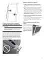
1.
Remove the oven-mounted junction box cover located
on the top rear of the oven. (See image below).
2.
Remove the cap from the conduit access hole in the
side of the oven-mounted junction box.
Position the decorative trim
piece so the flanges with
the holes in them face to
the rear of the oven.
Align the inner flanges with
the inside of the universal
brackets. Fasten with one
(1) screw each into the end
hole of the universal
bracket.
Tighten screws securely but
do not overtighten.

12
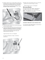
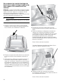
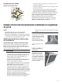
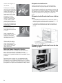
3.
Guide the wires from the conduit cable (coming from
the speed oven or steam convection oven through the
hole in the oven-mounted junction box. (See image
below). There are four wires from a speed oven or
three wires from a steam convection oven--no white
wire from a steam convection oven.
4.
Snap the conduit connector into the hole by pressing it
in until it clicks into place.
5.
Follow the wiring diagram label (see image below) and
match and connect each wire by color to the wires
attached to the wiring block inside the oven-mounted
junction box. Push the bare end of the wire until it is
snug in the wiring block then tighten down the
retaining screw on each wire.
Tighten securely, but do not overtighten.
See previous illustration in Step 3 for finished
appearance.
6.
Replace the oven-mounted junction box cover and
tighten the two screws holding it in place.
Tighten securely, but do not overtignten.
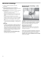
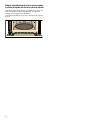
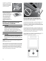
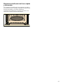
Microwave Models
Microwave Models HBL57M52UC, HBL87M52UC
Microwave Combo has a 120 Volt receptacle.
Note: 120V receptacle is to be used as the power
supply for HMB50152UC microwave.
Installation of Microwave to the Combination Oven
For microwave models HBL57M52UC, HBL87M52UC
see previous Installation Chapter.
95HFHSWDFOH
IRU0LFURZDYH

13
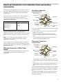
Electrical Installation of Combination Oven-Grounding
Instructions
The assembled combination oven should be moved in
front of the cabinet opening and the power cable from
the lower oven should be connected to the cabinet
junction box.
All model ovens on the front cover of this installation
instruction manual are dual rated, designed to be
connected to either 208 or 240V AC, 60 Hz, 4 wire,
single-phase power supply.
The electrical supply should be a 4-wire single phase AC.
Install a suitable conduit box (not furnished). An
appropriately-sized, UL-listed conduit connector must be
used to correctly attach the conduit to the junction box.
Note: Local codes may vary. Installation, electrical
connections and grounding must comply with all
applicable local codes.
If local codes permit grounding through the electrical
supply neutral, connect both the white neutral wire and
the green ground wire from the oven to the white neutral
eletrical supply wire.
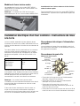
Electrical Connection to Main Power
Supply
The four-wire connection is preferred, but where local
codes permit, the three-wire connection is also
acceptable.
Four-wire Connection
Ungrounded Neutral
▯ Connect the red oven wire to the red electrical supply
wire (hot wire).
▯ Connect the black oven wire to the black electrical
supply wire (hot wire).
▯ Connect the white neutral oven wire to the white
neutral (not bare or green ground) electrical supply
wire.
▯ Connect the green ground oven wire to the bare or
green ground electrical supply wire.
Three-wire Connection
Grounded Neutral
▯ Connect red wire from oven to red wire in junction box.
▯ Connect black wire from oven to black wire in junction
box.
▯ Connect both green ground wire and white wire from
oven to white, green or bare neutral wire in junction
box.
The conduit cable, where connected at the oven, swivels.
Rotate conduit cable upward (or downward) and direct
through hole prepared in cabinet to attach to junction
box.
To maintain serviceability, the flex conduit must not be
shortened and should be routed to permit temporary
removal of the oven.
Model Circuit Required
HBL57M52UC
HBL87M52UC
HBL8752UC
HBLP752UC
208V, 60 Hz/ 240V, 60
Hz
40 AMP
SRZHUVXSSO\
MXQFWLRQER[
UHGZLUHV
JUHHQRUEDUH
JUHHQZLUH
8/OLVWHG
FDEOHIURP
ZKLWHZLUHV
EODFNZLUHV
ZLUH
FRQQHFWRU
RYHQ
SRZHUVXSSO\
MXQFWLRQER[
UHGZLUHV
ZKLWHEDUHRU
ZKLWHZLUH
JUHHQZLUH
JUHHQZLUH
FDEOHIURP
8/OLVWHG
EODFNZLUHV
RYHQ
FRQQHFWRU

14
Installing Combination Oven into Wall Cabinet
NOTICES
▯ Before installing the combination oven, be sure to
verify the cabinet dimensions and electrical
connections.
▯ Check that the cabinet opening is level and plumb for
correct installation.
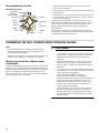
Remove Lower Oven Door Prior to
Installation
It is recommended to remove the traditional (lower) oven
door to help reduce the unit weight and provide easier
access to the latch levers located inside the oven. Do not
remove microwave, speed oven or steam convection
oven doors.
9 WARNING
▯ The oven door is heavy and fragile. Use both
hands to remove the oven door. The door front is
glass. Handle carefully to avoid breaking.
▯ Grasp only the sides of the oven door. Do not
grasp the handle as it may swing in your hand
and cause damage or injury.
▯ Failure to grasp the oven door firmly and properly
could result in personal injury or product damage.
▯ To avoid injury from hinge bracket snapping
closed, be sure that both latch levers are securely
in place before removing the door. Also, do not
force door open or closed--the hinge could be
damaged and injury could result.
▯ Do not lay removed door on sharp or pointed
objects as this could break the glass. Lay door on
a protected flat, smooth surface, positioned so
that the door cannot fall over.
Be sure to read all warn-
ings and cautions in the
installation manual
regarding the door
removal before attempting
to remove the door.
Open the door com-
pletely.
Flip latch levers on hinges
all the way down toward
you.
Holding the door firmly on
both sides and using both
hands, close the door
gently until it stops
against the latch levers,
about 30 degrees from
the closed position.
Carefully lift the door up
and out of the hinge slots.
Hold firmly; the door is
heavy.
Place the door in a conve-
nient and stable location
until you are ready to rein-
stall it. Lay the door on a
towel or section of protec-
tive foam padding to
avoid damage to the door
or the floor.

15
Correctly Lifting the Combination Oven
9 CAUTION
It is recommended to wear gloves and long sleeves
to protect hands and forearms from abrasion and
potential scratches during the lifting process. It is
also recommended to take off watches and jewelry
and to wear work shoes during installation for foot
protection.
9 CAUTION
Three people or proper equipment are needed to
safely lift the combination oven into the cabinet
opening.
NOTICE: DO NOT attempt to lift the unit by holding the
oven’s upper element.
There is a ridge across the top front of the lower oven
cavity. Lift by grasping this ridge with one hand while
placing the other hand on the back of the unit (for
helpers lifting from the sides of the unit). If a third helper
is lifting from the front, both hands should lift by holding
this ridge area.
Lifting Recommendations
Lift locations or gripping points (with lower oven door
removed).
Lift points or gripping points (1) on the front of the unit
are for lifting from the sides of the unit. Lift point (3) on
the front of the unit is for a third person to help lift the
unit.
Lift points or gripping points (2) on the back of the unit
shows the location of the opposite hand for the helpers
lifting from the sides of the unit. Adjust the location as
needed to facilitate the lift.
Wear gloves, a long sleeved shirt, and avoid sharp
edges to reduce the risk of cuts or abrasions to the arms
or hands.

16
Placing Combination Oven Into Cabinet
Opening
9 CAUTION
To avoid damage to the door, do not lift, pull or
push the unit during installation by using any oven
door handle as a gripping point.
When lifting the combined unit into place, avoid grasping
the upper element to avoid damaging it. See the
illustration below for the correct lifting point. This
illustration shows a detailed view of the oven cavity. Note
the location of the ridge inside the top of the cavity. This
is the area to grip from the front when lifting the
combined unit.
Installing the Oven into the Cabinet
1.
Lift the combination oven unit into the cabinet cutout
without allowing the unit base to contact the flooring.
2.
Guide the unit straight back into the cabinet cutout.
Note: Be careful not to crimp the flexible conduit
between the oven and the cabinet back wall. If
necessary, guide the flexible conduit into the wall of
cabinet access hole so it doesn’t prevent the unit from
being pushed all the way into the cabinet opening. The
oven should be straight and level.
3.
Push the unit straight in until the oven trim is flush with
the front of the cabinet trim.
4.
Install four (4) supplied screws through tap holes in
the right and left trim pieces to secure oven to
cabinetry.
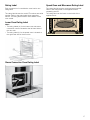
Re-Install the Lower Oven Door
Before Calling Service
See the Use and Care Manual for each unit of the
combination oven for troubleshooting information. Refer
to the Statement of Limited Warranty in the Use and Care
Manuals.
To reach a service representative, see the contact
information at the front of the Use and Care Manual.
Please be prepared with the information printed on your
product data plate when calling.
Hold the door firmly in
both hands.
Hold the door at an 30°
angle from the closed
position (approximately 7
inches open at the top).
Insert the hinges into the
slots.
You may need to rock the
door forward and back-
ward slightly to seat the
hinge feet. The door
should lower about 3/4”
and stop. If not, the
hinges have not engaged
properly and the door
could fall if it is released.
The door may need to be
removed and re-inserted
until the hinges sit cor-
rectly in the slots.
Open door all the way to
expose hinges, latch
levers and slots.
Push latch levers up until
they are locked into the
slots, flush with front of
the oven body.
Close and open door
slowly to be sure it is cor-
rectly and securely in
place. Door must be
straight.

17
Rating Label
Each component of a combination oven has its own
rating label.
The rating label shows the model, FD number and serial
number. Refer to the rating label when requesting
service. The rating label location varies based on the
oven model.
Lower Oven Rating Label
Notes
▯ The rating labels (A) for the lower oven and steam
convection oven are located at the left hand side of
the door trim.
▯ The rating label (A) for the speed oven is located at
the right hand side of the door trim.
Steam Convection Oven Rating Label
Speed Oven and Microwave Rating Label
The rating label shows the model and serial number.
Refer to the rating label on the appliance when
requesting service.
The rating label can be found on the inside of the
appliance door.

18
Table des matières
Notice de montage
Définitions de sécurité ................................................ 19
IMPORTANTES CONSIGNES DE SÉCURITÉ ............. 20
Sécurité de manutention des appareils ........................ 20
Codes et normes de sécurité ......................................... 20
Sécurité électrique ............................................................ 20
Équipement de sécurité ................................................... 21
Fours combinés Bosch ............................................... 22
Avant de commencer .................................................. 23
Outils et pièces nécessaires ........................................... 23
Exigences électriques et mise à la terre ...................... 23
Pour de meilleurs résultats d'installation ...................... 23
Liste de vérification ........................................................... 23
Dimensions et exigences concernant les armoires . 24
Installation traditionnelle d'un four combiné
et d'un four à micro-ondes à cuisson rapide
ou d'un four à vapeur et à convection
76 cm (30 po) ................................................................... 24
Installation encastrée d'un four combiné et
d'un four à micro-ondes à cuisson rapide ou
d'un four à convection et à vapeur 76 cm (30 po) .... 25
Retrait de l’emballage ................................................. 26
Retrait des brides d'emballage – côtés gauche
et droit ................................................................................. 26
Préparation des fours ....................................................... 26
Installation .................................................................... 27
Pré-assemblage de four combiné .................................. 27
Pièces fournies .................................................................. 27
Installation avec four à micro-ondes à cuisson
rapide ou avec four à micro-ondes ............................... 27
Installation avec four à et à convection ........................ 28
Raccordement du conduit électrique du four à
micro-ondes à cuisson rapide ou du four à vapeur
et à convection au four inférieur .................................... 30
Modèles de fours à micro-ondes .................................. 31
Installation électrique d'un four combiné –
Instructions de mise à la terre ................................... 31
Raccordement électrique à l'alimentation principale . 31
Raccordement à quatre fils ............................................. 31
Raccordement à trois fils ................................................ 32
Installation du four combiné dans l'armoire murale 32
Retirez la porte du four inférieur avant l'installation ... 32
Soulèvement approprié du four ..................................... 33
Recommandations concernant le soulèvement .......... 33
Installation du four combiné dans l'ouverture de
l'armoire .............................................................................. 34
Installation du four dans l'armoire ................................. 34
Remettre les portes du four inférieur en place ........... 35
Avant d'appeler le service de dépannage ................... 35
Plaque signalétique .......................................................... 35
Plaque signalétique du four inférieur ............................ 35
Plaque signalétique du four à vapeur et à convection 35
Plaque signalétique du four à micro-ondes à
cuisson rapide ou du four à micro-ondes .................... 36
9RXVDYH]GHVTXHVWLRQV"
ZZZERVFKKRPHFRPXV
ââ
1RXVQRXVIHURQVXQSODLVLUGHYRXVVHUYLU
&HWDSSDUHLOpOHFWURPpQDJHU%RVFKHVWIDEULTXpSDU
%6++RPH$SSOLDQFHV&RUSRUDWLRQ
0DLQ6WUHHW6XLWH
,UYLQH&$

19
Définitions de sécurité
9 AVERTISSEMENT
Ceci indique que le non-respect de cet
avertissement peut entraîner des blessures graves,
voire la mort.
9 ATTENTION
Ceci indique que le non-respect de cet
avertissement peut entraîner des blessures légères
ou de gravité moyenne.
AVIS : Ceci indique que la non-conformité à cet avis de
sécurité peut entraîner des dégâts matériels ou
endommager l'appareil.
Remarque : Ceci vous signale des informations et/ou
indications importantes.

9 IMPORTANTES CONSIGNES DE SÉCURITÉ
LIRE ET CONSERVER CES INSTRUCTIONS
20
IMPORTANTES CONSIGNE LIRE ET CONSERVER CES INSTRUCTIONS
IMPORTANT : CONSERVEZ CES CONSIGNES À
L'INTENTION DE L'INSPECTEUR EN ÉLECTRICITÉ.
INSTALLATEUR : PRIÈRE DE LAISSER CES
INSTRUCTIONS D'INSTALLATION AVEC CET APPAREIL
À L'INTENTION DU PROPRIÉTAIRE.
PROPRIÉTAIRE : PRIÈRE DE CONSERVER CES
INSTRUCTIONS POUR POUVOIR VOUS Y RÉFÉRER
ULTÉRIEUREMENT.
AVERTISSEMENT
Correctement entretenu, votre nouvel appareil a été
conçu pour être sécuritaire et fiable. Lisez toutes les
instructions attentivement avant l’utilisation. Ces
consignes réduiront le risque de brûlure, d'électrocution,
d’incendie et de blessure pour les personnes utilisant
l'appareil. Lorsque vous utilisez des appareils
électroménagers, il importe de suivre les précautions de
sécurité de base, y compris celles indiquées dans les
pages suivantes.
AVERTISSEMENT
Ne réparez, remplacez, ni ne retirez aucune partie de
l'appareil, excepté si les manuels recommandent de le
faire. Une installation, un entretien ou une inspection
incorrects peuvent occasionner des blessures ou des
dommages matériels. Reportez-vous au présent manuel
pour obtenir des indications. Toute autre intervention doit
être effectuée par un technicien agréé.
Sécurité de manutention des appareils
ATTENTION
Codes et normes de sécurité
Cet appareil est conforme aux plus récentes versions de
l'une ou plus des normes suivantes :
▯ UL 858, cuisinières électriques domestiques
▯ UL 923, fours à micro-ondes
▯ UL 507, la norme en matière de sécurité pour les
ventilateurs électriques
▯ CAN/CSA-C22.2 No 113-M1984 Ventilateurs
Il incombe au propriétaire et à l'installateur de déterminer
si des exigences et/ou normes additionnelles
s'appliquent pour des installations spécifiques.
Sécurité électrique
AVERTISSEMENT
Avant tout raccordement de cordon électrique ou toute
mise sous tension, assurez-vous que toutes les
commandes sont en position OFF (d'arrêt).
Ne laissez pas le cordon pendre de la table ou du
comptoir, ni entrer en contact avec les surfaces chaudes.
Branchez toujours la fiche à l'appareil en premier avant
de la raccorder à la prise murale. Pour débrancher
l'appareil, mettez tous les boutons de réglage en position
« off » (arrêt) et retirez ensuite la fiche de la prise murale.
N'utilisez pas l'appareil avec une fiche ou un cordon
endommagé ou encore si l'appareil ne fonctionne pas
correctement ou a été endommagé de quelconque
façon. Il n'est pas sécuritaire d'utiliser un appareil avec
une fiche ou un cordon endommagé. Si l'appareil a été
endommagé ou qu'il ne fonctionne pas correctement,
débranchez l'appareil de l'alimentation électrique de
façon sécuritaire et contactez immédiatement un
technicien qualifié pour une inspection du produit.
Pour se protéger contre toute décharge électrique, ne
pas immerger le cordon, les prises ou d'autres pièces
électriques de l'appareil dans de l'eau ou un autre
liquide.
Pour les appareils dotés d'un cordon d'alimentation avec
fiche, ne pas couper ni enlever la broche de mise à la
terre. Pour éviter toute décharge électrique, branchez le
cordon sur une prise de courant correspondante avec
mise à la terre. En cas de doute concernant la mise à la
terre appropriée de la prise murale, le client doit faire
vérifier celle-ci par un électricien qualifié. N'utilisez PAS
de rallonge ou d'adaptateur.
▯ L'unité est lourde et son déplacement exige au
moins deux personnes ou encore un
équipement approprié.
▯ Ne soulevez pas l'appareil par la poignée de
porte.
▯ Les surfaces cachées peuvent comporter des
arêtes vives. Redoublez de vigilance quand
vous passez la main derrière ou sous
l'appareil.
La page est en cours de chargement...
La page est en cours de chargement...
La page est en cours de chargement...
La page est en cours de chargement...
La page est en cours de chargement...
La page est en cours de chargement...
La page est en cours de chargement...
La page est en cours de chargement...
La page est en cours de chargement...
La page est en cours de chargement...
La page est en cours de chargement...
La page est en cours de chargement...
La page est en cours de chargement...
La page est en cours de chargement...
La page est en cours de chargement...
La page est en cours de chargement...
La page est en cours de chargement...
La page est en cours de chargement...
La page est en cours de chargement...
La page est en cours de chargement...
La page est en cours de chargement...
La page est en cours de chargement...
La page est en cours de chargement...
La page est en cours de chargement...
La page est en cours de chargement...
La page est en cours de chargement...
La page est en cours de chargement...
La page est en cours de chargement...
La page est en cours de chargement...
La page est en cours de chargement...
La page est en cours de chargement...
La page est en cours de chargement...
La page est en cours de chargement...
La page est en cours de chargement...
La page est en cours de chargement...
La page est en cours de chargement...
-
 1
1
-
 2
2
-
 3
3
-
 4
4
-
 5
5
-
 6
6
-
 7
7
-
 8
8
-
 9
9
-
 10
10
-
 11
11
-
 12
12
-
 13
13
-
 14
14
-
 15
15
-
 16
16
-
 17
17
-
 18
18
-
 19
19
-
 20
20
-
 21
21
-
 22
22
-
 23
23
-
 24
24
-
 25
25
-
 26
26
-
 27
27
-
 28
28
-
 29
29
-
 30
30
-
 31
31
-
 32
32
-
 33
33
-
 34
34
-
 35
35
-
 36
36
-
 37
37
-
 38
38
-
 39
39
-
 40
40
-
 41
41
-
 42
42
-
 43
43
-
 44
44
-
 45
45
-
 46
46
-
 47
47
-
 48
48
-
 49
49
-
 50
50
-
 51
51
-
 52
52
-
 53
53
-
 54
54
-
 55
55
-
 56
56


Bosch HBL8742UC Guide d'installation
- Catégorie
- Fours
- Taper
- Guide d'installation
- Ce manuel convient également à
dans d''autres langues
- English: Bosch HBL8742UC Installation guide
- español: Bosch HBL8742UC Guía de instalación