Toro Flex-Force Power System 60V MAX String Trimmer Manuel utilisateur
- Catégorie
- Outils électroportatifs
- Taper
- Manuel utilisateur

Form No. 3460-934 Rev A
Flex-Force Power System™ 60V MAX String T rimmer
51836
Desbrozadora de hilo con Flex-Force Power System™
60 V MAX
51836
Débroussailleuse à l Flex-Force Power System™ 60
V MAX
51836
www .T oro.com.
*3460-934*


Form No. 3460-931 Rev A
Flex-Force Power System
™
60V
MAX String T rimmer
Model No. 51836 —Serial No. 323000001 and Up
Register at www .T oro.com.
Original Instructions (EN)
*3460-931*

For assistance, please see
www .T oro.com/support
for instructional videos
or contact 1-888-384-9939
before returning this
product.
W ARNING
CALIFORNIA
Proposition 65 W arning
The power cord on this product contains
lead, a chemical known to the State
of California to cause birth defects
or other reproductive harm. W ash
hands after handling.
Use of this product may cause exposure
to chemicals known to the State of
California to cause cancer , birth defects,
or other reproductive harm.
Introduction
This trimmer is intended to be used by residential
homeowners to trim grass as needed outdoors. This
power head is intended to be used by residential
homeowners to power attachment tools. It is designed
to be used only in combination with T oro Flex-Force
Power System 60V Max attachments. It is designed
to use T oro 60V lithium-ion battery packs. These
battery packs are designed to be charged only by T oro
60V lithium-ion battery chargers. Using this product
for purposes other than its intended use could prove
dangerous to you and bystanders.
Read this information carefully to learn how to operate
and maintain your product properly and to avoid
injury and product damage. Y ou are responsible for
operating the product properly and safely .
V isit www .T oro.com for product safety and operation
training materials, accessory information, help nding
a dealer , or to register your product.
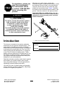
Whenever you need service, genuine the
manufacturer parts, or additional information, contact
an Authorized Service Dealer or the manufacturer
Customer Service and have the model and serial
numbers of your product ready . Figure 1 identies
the location of the model and serial numbers on the
product. W rite the numbers in the space provided.
Important: W ith your mobile device, you can
scan the QR code on the serial number decal (if
equipped) to access warranty , parts, and other
product information.
g372937
Figure 1
1. Model and serial number locations
Model No.
Serial No.
© 2023—The T oro® Company
81 1 1 L yndale A venue South
Bloomington, MN 55420
2
Contact us at www .T oro.com.
Printed in China
All Rights Reserved

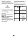
Safety-Alert Symbol
The safety-alert symbol ( Figure 1 ) shown in this
manual and on the machine identies important safety
messages that you must follow to prevent accidents.
g000502
Figure 2
Safety-alert symbol
The safety-alert symbol appears above information
that alerts you to unsafe actions or situations and
is followed by the word DANGER ,W ARNING , or
CAUTION .
DANGER indicates an imminently hazardous situation
which, if not avoided, will result in death or serious
injury .
W ARNING indicates a potentially hazardous situation
which, if not avoided, could result in death or serious
injury .
CAUTION indicates a potentially hazardous situation
which, if not avoided, may result in minor or moderate
injury .
This manual uses two other words to highlight
information. Important calls attention to special
mechanical information and Note emphasizes general
information worthy of special attention.
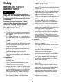
Model 51836 includes Model 51810T Power Head
and the Model 88716 String T rimmer Attachment.
The Model 51810T Power Head is compatible with
a variety of T oro-approved attachments that, when
combined, comply with specic standards; see the
following table for more detail.
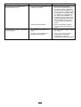
Combination
Power
Head
Model
Attachment
Model
Standard
String
T rimmer
51810T 88716
Conforms to
UL STD 82
Certied to CSA
STD C22.2 No. 147
Edger 51810T 88710
Conforms to
UL STD 82
Certied to CSA
STD C22.2 No. 147
Pole Saw
51810T 88714
Conforms to
UL STD 82
Certied to CSA
STD C22.2 No. 147
Cultivator
51810T 88715
Conforms to
UL STD 82
Certied to CSA
STD C22.2 No. 147
Hedge
T rimmer
51810T 88713
Conforms to UL
STD 62841-4-2
Certied to CSA STD
C22.2 62841-4-2
3

Safety
IMPORT ANT SAFETY
INSTRUCTIONS
W ARNING
When using electric gardening appliances,
always read and follow basic safety warnings
and instructions to reduce the risk of re,
electric shock, and personal injury , including
the following:
In addition to these instructions, always
read and follow the safety warnings and
instructions included with your specic
attachment before operating the power head.
Read All Instructions
I. T raining
1. The operator of the appliance is responsible for
any accidents or hazards occurring to others or
their property .
2. Do not allow children to use or play with the
appliance, battery pack, or the battery charger;
local regulations may restrict the age of the
operator .
3. Do not allow children or untrained people to
operate or service this device. Allow only people
who are responsible, trained, familiar with the
instructions, and physically capable to operate
or service the device.
4. Before using the appliance, battery pack, and
battery charger , read all the instructions and
cautionary markings on these products.
5. Become familiar with the controls and proper
use of the appliance, battery pack, and battery
charger .
II. Preparation
1. Keep bystanders and children away from the
operating area.
2. Use only the battery pack specied by T oro.
Using other accessories and attachments may
increase the risk of injury and re.
3. Plugging the battery charger into an outlet that is
not 120 V can cause a re or electric shock. Do
not plug the battery charger into an outlet other
than 120 V . For a dif ferent style of connection,
use an attachment plug adapter of the proper
conguration for the power outlet if needed.
4. Do not use a damaged or modied battery
pack or battery charger , which may exhibit
unpredictable behavior that results in re,
explosion, or risk of injury .
5. If the supply cord to the battery charger is
damaged, contact an Authorized Service Dealer
to replace it.
6. Charge the battery pack with only the battery
charger specied by T oro. A charger suitable for
1 type of battery pack may create a risk of re
when used with another battery pack.
7. Charge the battery pack in a well-ventilated area
only .
8. Follow all charging instructions and do
not charge the battery pack outside of the
temperature range specied in the instructions.
Otherwise, you may damage the battery pack
and increase the risk of re.
9. Do not operate the appliance without all guards
and other safety protective devices in place and
functioning properly on the appliance.
10. Dress properly—W ear appropriate clothing,
including eye protection; long pants; substantial,
slip-resistant footwear; rubber gloves; and
hearing protection. T ie back long hair and do
not wear loose clothing or loose jewelry that can
get caught in moving parts. W ear a dust mask in
dusty operating conditions.
III. Operation
1. Do not operate the power head without an
attachment installed.
2. A void dangerous environments—Do not use the
appliance in rain or in damp or wet locations.
3. Use the proper appliance for your
application—Using the appliance for
purposes other an its intended use could prove
dangerous to you and bystanders.
4. Prevent unintentional starting—Ensure that the
switch is in the O FF position before connecting
to the battery pack and handling the appliance.
Do not carry the appliance with your nger on
the switch or energize the appliance with the
switch in the O Nposition.
5. Operate the appliance only in daylight or good
articial light.
6. If the tool strikes an object or starts to vibrate,
immediately shut of f the tool, wait for all moving
parts to stop, and disconnect the battery before
examining the tool for damage. Make all
necessary repairs before resuming operation
7. Remove the battery pack from the appliance
before adjusting it or changing accessories.
8. Keep your hands and feet away from the cutting
area and all moving parts.
4

9. Stop the appliance, remove the battery pack
from the appliance, and wait for all movement
to stop before adjusting, servicing, cleaning, or
storing the appliance.
10. Remove the battery pack from the appliance
whenever you leave it unattended.
1 1. Do not force the appliance—Allow the appliance
to do the job better and safer at the rate for
which it was designed.
12. Do not overreach—Keep proper footing and
balance at all times, especially on slopes. W alk,
never run with the appliance.
13. Stay alert—W atch what you are doing and use
common sense when operating the appliance.
Do not use the appliance while ill, tired, or under
the inuence of alcohol or drugs.
14. Ensure that the ventilation openings are kept
clear of debris.
15. Under abusive conditions, the battery pack may
eject liquid; avoid contact. If you accidently
come into contact with the liquid, ush with
water . If the liquid contacts your eyes, seek
medical help. Liquid ejected from the battery
pack may cause irritation or burns.
16. Do not expose a battery pack or tool to re or
excessive temperature. Exposure to re or
temperature above 130°C (265°F) may cause
explosion.
17. CAUTION—A mistreated battery pack may
present a risk of re, explosion, or chemical
burn.
•Do not disassemble the battery pack.
•Replace the battery pack with a genuine
T oro battery pack only; using another type of
battery pack may cause a re or risk of injury .
•Keep battery packs out of the reach of
children and in the original packaging until
you are ready to use them.
IV . Maintenance and Storage
1. Maintain the appliance with care—Keep it clean
and in good repair for best performance and to
reduce the risk of injury . Follow the instructions
for lubricating and changing accessories. Keep
handles dry , clean, and free from oil and grease.
2. When the battery pack is not in use, keep it
away from metal objects such as paper clips,
coins, keys, nails, and screws that can make a
connection from 1 terminal to another . Shorting
the battery terminals may cause burns or a re.
3. Keep your hands and feet away from moving
parts.
4. Shut of f the appliance, remove the battery pack
from the appliance, and wait for all movement
to stop before adjusting, servicing, cleaning, or
storing the appliance.
5. Check the appliance for damaged parts—If there
are damaged guards or other parts, determine
whether it will operate properly . Check for
misaligned and binding moving parts, broken
parts, mounting, and any other condition that
may af fect its operation. Unless indicated in the
instructions, have an Authorized Service Dealer
repair or replace a damaged guard or part.
6. Do not replace the existing non-metallic cutting
means on the appliance with a metallic cutting
means.
7. Do not attempt to service or repair the appliance,
battery pack, or battery charger except as
indicated in the instructions. Have an Authorized
Service Dealer perform service using identical
replacement parts to ensure that the product is
safely maintained.
8. Store an idle appliance indoors in a place that is
dry , secure, and out of the reach of children.
9. Do not dispose of the battery in a re. The
cell may explode. Check with local codes for
possible special disposal instructions.
SA VE THESE
INSTRUCTIONS
5

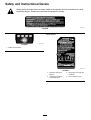
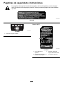
Safety and Instructional Decals
Safety decals and instructions are easily visible to the operator and are located near any area
of potential danger . Replace any decal that is damaged or missing.
decal139-5346
139-5346
decal137-9461
137-9461
1. Battery charge status
Model 88625
decal137-9454
137-9454
1. Read the Operator ’ s
Manual .
3. Keep away from open re
or ames.
2. Call2Recycle
®
battery
recycling program
4. Do not expose to rain.
6

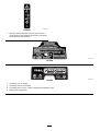
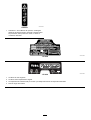
decal139-5210
139-5210
1. W arning—read the Operator ’ s Manual ; stay away from
moving parts; keep all guards in place; wear eye protection;
do not operate in wet conditions.
decal137-9462
137-9462
decal137-9463
137-9463
1. The battery pack is charging.
2. The battery pack is fully charged.
3. The battery pack is over or under the appropriate temperature range.
4. Battery pack charging fault
7

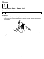
Setup
1
Installing the Battery Guard Rod
Parts needed for this procedure:
1 Battery guard rod
Procedure
1. Align the arms of the guard rod with the guide on the power head.
2. Lightly pull the arms of the guard rod so that they t around the power head, and t the rod ends into the
mounting holes.
g385364
Figure 3
1. Battery guard rod 3. Mounting hole
2. Rod guide
8

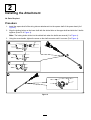
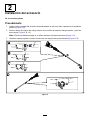
2
Installing the Attachment
No Parts Required
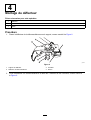
Procedure
1. Install the square shaft of the string trimmer attachment into the square shaft of the power head (A of
Figure 4 ).
2. Align the locking button on the lower shaft with the slotted hole on the upper shaft and slide the 2 shafts
together (B and C of Figure 4 ).
Note: The locking button clicks into the slotted hole when the shafts are secured (C of Figure 4 ).
3. Using the screw-handle, tighten the screw on the shaft connector until it is secure (D of Figure 4 ).
g357440
Figure 4
9

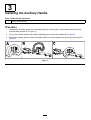
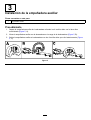
3
Installing the Auxiliary Handle
Parts needed for this procedure:
1 Auxiliary handle assembly
Procedure
1. Separate the auxiliary handle from the handle plate by removing the 4 socket head screws using the
provided Allen wrench (A of Figure 5 ).
2. Line up the auxiliary handle with auxiliary handle plate on the trimmer handle (B of Figure 5 ).
3. Secure the auxiliary handle to the handle plate with the 4 socket head screws previously removed (C of
Figure 5 ).
g357443
Figure 5
10

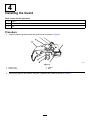
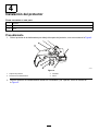
4
Installing the Guard
Parts needed for this procedure:
1
Guard
4 W asher
4 Bolt
Procedure
1. Align the trimmer guard beneath the guard mount as shown in Figure 6 .
g333216
Figure 6
1. Guard mount
3. W asher
2. T rimmer guard 4. Bolt
2. Secure the guard to the trimmer using the 4 washers and 4 bolts as shown in Figure 6 .
1 1

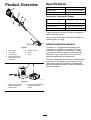
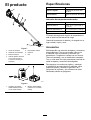
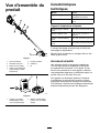
Product Overview
g357427
Figure 7
1. Battery latch 5. Auxiliary handle
2. Run trigger
6. Guard
3. Lockout button
7. String
4. Harness/strap collar
(harness/strap sold
separately)
g362427
Figure 8
1. Battery charger Model
88602 (included with
Model 51836)
2. Battery pack Model 88625
(included with Model
51836)
Specications
Model 51836
Charger T ype
T oro 60V lithium-ion chargers
Battery T ype T oro 60V lithum-ion batteries
Appropriate T emperature Ranges
Charge/store the battery pack
at
5°C (41°F) to 40°C (104°F)*
Use the battery pack at
-30°C (-22°F) to 49°C (120°F)
Use the trimmer at
0°C (32°F) to 49°C (120°F)
Store the trimmer at 0°C (32°F) to 49°C (120°F)*
*Charging time will increase if you do not charge the
battery within this range.
Store the tool, battery pack, and battery charger in an
enclosed clean, dry area.
Attachments/Accessories
A selection of T oro approved attachments and
accessories is available for use with the machine
to enhance and expand its capabilities. Contact
your Authorized Service Dealer or authorized T oro
distributor or go to www .T oro.com for a list of all
approved attachments and accessories.
T o ensure optimum performance and continued safety
certication of the machine, use only genuine T oro
replacement parts and accessories. Replacement
parts and accessories made by other manufacturers
could be dangerous.
12

Operation
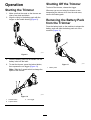
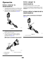
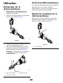
Starting the T rimmer
1. Make sure that the vents on the trimmer are
clear of any dust and debris.
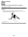
2. Align the cavity in the battery pack with the
tongue on the handle housing ( Figure 9 ).
g357444
Figure 9
3. Push the battery pack into the handle until the
battery locks into the latch.
4. T o start the trimmer , press the lockout button,
then squeeze the run trigger ( Figure 10 ).
Note: Slide the 2-speed switch to change the
speed of the trimmer .
g357456
Figure 10
1. Lockout button 3. Run trigger
2. 2-speed switch
Shutting Off the T rimmer
T o shut of f the trimmer , release the trigger .
Whenever you are not using the trimmer or are
transporting the trimmer to or from the work area,
remove the battery pack.
Removing the Battery Pack
from the T rimmer
Press the battery latch on the machine to release the
battery pack and slide the battery pack out of the
machine ( Figure 1 1 ).
g357457
Figure 1 1
1. Battery latch
13

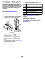
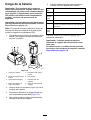
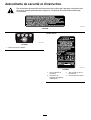
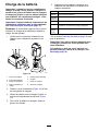
Charging the Battery Pack
Important: The battery pack is not fully charged
when you purchase it. Before using the tool for
the rst time, place the battery pack in the charger
and charge it until the LED display indicates the
battery pack is fully charged. Read all safety
precautions.
Important: Charge the battery pack only in
temperatures that are within the appropriate
range; refer to Specications ( page 12 ) .
Note: At any time, press the battery-charge-indicator
button on the battery pack to display the current
charge (LED indicators).
1. Ensure that the vents on the battery and battery
charger are clear of any dust and debris.
g290533
Figure 12
1. Battery pack cavity
5. LED indicators (current
charge)
2. Battery pack venting areas 6. Handle
3. Battery pack terminals
7. Charger LED indicator
light
4. Battery-charge-indicator
button
8. Charger venting areas
2. Line up the cavity in the battery pack ( Figure 12 )
with the tongue on the charger .
3. Slide the battery pack into the charger until it is
fully seated ( Figure 12 ).
4. T o remove the battery pack, slide the battery
backward out of the charger .
5. Refer to the following table to interpret the LED
indicator light on the battery charger .
Indicator
light
Indicates
Of f
No battery pack inserted
Green
blinking
Battery pack is charging
Green
Battery pack is charged
Red
Battery pack and/or battery charger is over or under
the appropriate temperature range
Red
blinking
Battery pack charging fault*
*Refer to T roubleshooting ( page 19 ) for more
information.
Important: The battery can be left on the charger
for short periods between uses.
If the battery will not be used for longer periods,
remove the battery from the charger; refer to
Storage ( page 18 ) .
14

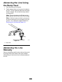
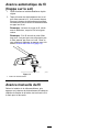
Advancing the Line Using
the Bump Feed
1. Run the trimmer at full throttle.
2. T ap the bump button on the ground to advance
the line. The line advances each time the bump
button is tapped. Do not hold the bump button
on the ground.
Note: The line trimming cut-of f blade on the
grass deector cuts the line to the correct length.
Note: If the line is worn too short, you may not
be able to advance the line by tapping it on the
ground. If so, release the trigger and refer to
Advancing the Line Manually ( page 15 ) .
g331007
Figure 13
1. Bump button
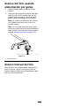
Advancing the Line
Manually
Remove the battery pack from the trimmer , then push
the bump button at the base of the spool retainer
while pulling on the trimmer line to manually advance
the line.
15

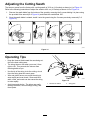
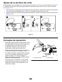
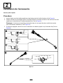
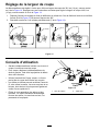
Adjusting the Cutting Swath
The trimmer comes from the factory with a cutting swath of 36.6 cm (14 inches) as shown in A of Figure 14 .
Refer to the following instructions to adjust the swath to 40.6 cm (16 inches) as shown in D of Figure 14 .
1. Remove the swath blade from the bottom of the guard by removing the 2 screws holding it in place using
the provided Allen wrench (B of Figure 14 ) and rotate the swath blade 180°.
2. Once the swath blade is rotated, install it onto the guard using the 2 screws previously removed (C of
Figure 14 ).
g427004
Figure 14
Operating T ips
•Keep the trimmer tilted toward the area being cut;
this is the best cutting area.
•The string trimmer cuts when you move it from
right to left. This prevents the trimmer from
throwing debris at you.
•Use the tip of the string to do the cutting; do not
force the string head into uncut grass.
•Wire and picket fences can cause the string to
wear rapidly and even break. Stone and brick
walls, curbs, and wood can also cause the string
to wear rapidly .
•A void trees and shrubs. The string can easily
damage tree bark, wood moldings, siding, and
fence posts.
g330996
Figure 15
1. Direction of rotation 2. String path
16

Maintenance
After each use of the trimmer , complete the following:
1. Remove the battery from the trimmer .
2. Wipe the trimmer clean with a damp cloth. Do
not hose the trimmer down or submerge it in
water .
CAUTION
The line cutoff blade on the deector is
sharp and can cut you.
Do not use your hands to clean the
deector shield and blade.
3. Wipe or scrape clean the cutting head area any
time there is an accumulation of debris.
4. Check and tighten all fasteners. If any part is
damaged or lost, repair or replace it.
5. Brush debris away from air intake vents and
exhaust on motor housing to prevent the motor
from overheating.
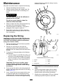
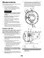
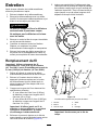
Replacing the String
Important: Use only 2 mm (0.080 inch) diameter
monolament string (T oro Part No. 8861 1) or 2.4
mm (0.095 inch) diameter twisted monolament
string (T oro Part No. 88202).
1. Remove the battery pack and clean any debris
from the trimmer head.
2. Remove any old string on the spool by
repetitively pressing the bump button while
pulling the line out equally from both sides of the
trimmer .
3. Cut a piece of string according to the following
specications.
•If you are using 2 mm (0.080 inch) string, cut
one piece of line approximately 4.9 m (16 ft).
•If you are using 2.4 mm (0.095 inch) twisted
string, cut one piece of line approximately 3
m (10 ft).
Important: Do not use any other gauge
or type of string, and do not exceed the
recommended length as this could damage
the trimmer .
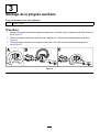
4. Press and turn the knob on the string head until
arrow on the knob aligns with arrow on the string
head ( Figure 16 ).
5. Insert 1 end of the line at an angle into the LINE
IN eyelet and push the line through the string
head track until it comes out through the eyelet
on the other side. Pull the line though the string
head until the line outside the string is evenly
divided on each side.
g330983
g330985
Figure 16
Disassembled view shown for clarity
1. Arrows 4. Eyelet
2. Knob
5. String
3. String head
6. T rack
Important: Do not disassemble the trimmer
head.
6. Hold the string head in place with one hand.
With your other hand, rotate the knob in the
direction shown by the arrows (clockwise).
7. Wind the line, leaving about 102 mm (4 inches)
extending beyond the eyelet on each side.
17

Storage
Important: Store the tool, battery pack, and
charger only in temperatures that are within the
appropriate range; refer to Specications ( page
12 ) .
Important: If you are storing the battery pack for
the off-season, remove the battery pack from the
tool and charge the battery pack until 2 or 3 LED
indicators turn green on the battery . Do not store
a fully charged or fully depleted battery . When you
are ready to use the tool again, charge the battery
pack until the left indicator light turns green on
the charger or all 4 LED indicators turn green on
the battery .
•Disconnect the product from the power supply
(i.e., remove the plug from the power supply or the
battery pack) and check for damage after use.
•Do not store the tool with the battery pack installed.
•Clean all foreign material from the product.
•When not in use, store the tool, battery pack, and
battery charger out of the reach of children.
•Keep the tool, battery pack, and battery charger
away from corrosive agents, such as garden
chemicals and de-icing salts.
•T o reduce the risk of serious personal injury , do
not store the battery pack outside or in vehicles.
•Store the tool, battery pack, and battery charger
in an enclosed clean, dry area.
Preparing the Battery Pack
for Recycling
Important: Upon removal, cover the terminals of
the battery pack with heavy-duty adhesive tape.
Do not attempt to destroy or disassemble the
battery pack or remove any of its components.
Lithium-ion battery packs labeled with the
Call2Recycle seal can be recycled at any
participating retailer or battery recycling
facility in the Call2Recycle program (US
and Canada only). T o locate a participating
retailer or facility closest to you, please call
1-800-822-8837 or visit www .call2recycle.org.
If you cannot locate a participating retailer or
facility nearby , or if your rechargeable battery
is not labeled with the Call2Recycle seal,
please contact your local municipality for more
information on how to responsibly recycle the
battery . If you are located outside of the US
and Canada, please contact your authorized
T oro distributor .
18
La page est en cours de chargement...
La page est en cours de chargement...
La page est en cours de chargement...
La page est en cours de chargement...
La page est en cours de chargement...
La page est en cours de chargement...
La page est en cours de chargement...
La page est en cours de chargement...
La page est en cours de chargement...
La page est en cours de chargement...
La page est en cours de chargement...
La page est en cours de chargement...
La page est en cours de chargement...
La page est en cours de chargement...
La page est en cours de chargement...
La page est en cours de chargement...
La page est en cours de chargement...
La page est en cours de chargement...
La page est en cours de chargement...
La page est en cours de chargement...
La page est en cours de chargement...
La page est en cours de chargement...
La page est en cours de chargement...
La page est en cours de chargement...
La page est en cours de chargement...
La page est en cours de chargement...
La page est en cours de chargement...
La page est en cours de chargement...
La page est en cours de chargement...
La page est en cours de chargement...
La page est en cours de chargement...
La page est en cours de chargement...
La page est en cours de chargement...
La page est en cours de chargement...
La page est en cours de chargement...
La page est en cours de chargement...
La page est en cours de chargement...
La page est en cours de chargement...
La page est en cours de chargement...
La page est en cours de chargement...
La page est en cours de chargement...
La page est en cours de chargement...
La page est en cours de chargement...
La page est en cours de chargement...
La page est en cours de chargement...
La page est en cours de chargement...
La page est en cours de chargement...
La page est en cours de chargement...
-
 1
1
-
 2
2
-
 3
3
-
 4
4
-
 5
5
-
 6
6
-
 7
7
-
 8
8
-
 9
9
-
 10
10
-
 11
11
-
 12
12
-
 13
13
-
 14
14
-
 15
15
-
 16
16
-
 17
17
-
 18
18
-
 19
19
-
 20
20
-
 21
21
-
 22
22
-
 23
23
-
 24
24
-
 25
25
-
 26
26
-
 27
27
-
 28
28
-
 29
29
-
 30
30
-
 31
31
-
 32
32
-
 33
33
-
 34
34
-
 35
35
-
 36
36
-
 37
37
-
 38
38
-
 39
39
-
 40
40
-
 41
41
-
 42
42
-
 43
43
-
 44
44
-
 45
45
-
 46
46
-
 47
47
-
 48
48
-
 49
49
-
 50
50
-
 51
51
-
 52
52
-
 53
53
-
 54
54
-
 55
55
-
 56
56
-
 57
57
-
 58
58
-
 59
59
-
 60
60
-
 61
61
-
 62
62
-
 63
63
-
 64
64
-
 65
65
-
 66
66
-
 67
67
-
 68
68


Toro Flex-Force Power System 60V MAX String Trimmer Manuel utilisateur
- Catégorie
- Outils électroportatifs
- Taper
- Manuel utilisateur