Asus Pro WS TRX50-SAGE WIFI Manuel utilisateur
- Catégorie
- Cartes mères
- Taper
- Manuel utilisateur

Motherboard
Pro WS
TRX50-SAGE
WIFI

ii
E23017
Revised Edition V2
December 2023
Copyright © 2023 ASUSTeK COMPUTER INC. All Rights Reserved.
No part of this manual, including the products and software described in it, may be reproduced,
transmitted, transcribed, stored in a retrieval system, or translated into any language in any form or by
any means, except documentation kept by the purchaser for backup purposes, without the express
written permission of ASUSTeK COMPUTER INC. (“ASUS”).
Product warranty or service will not be extended if: (1) the product is repaired, modified or altered, unless
such repair, modification of alteration is authorized in writing by ASUS; or (2) the serial number of the
product is defaced or missing.
ASUS PROVIDES THIS MANUAL “AS IS” WITHOUT WARRANTY OF ANY KIND, EITHER EXPRESS
OR IMPLIED, INCLUDING BUT NOT LIMITED TO THE IMPLIED WARRANTIES OR CONDITIONS OF
MERCHANTABILITY OR FITNESS FOR A PARTICULAR PURPOSE. IN NO EVENT SHALL ASUS, ITS
DIRECTORS, OFFICERS, EMPLOYEES OR AGENTS BE LIABLE FOR ANY INDIRECT, SPECIAL,
INCIDENTAL, OR CONSEQUENTIAL DAMAGES (INCLUDING DAMAGES FOR LOSS OF PROFITS,
LOSS OF BUSINESS, LOSS OF USE OR DATA, INTERRUPTION OF BUSINESS AND THE LIKE),
EVEN IF ASUS HAS BEEN ADVISED OF THE POSSIBILITY OF SUCH DAMAGES ARISING FROM
ANY DEFECT OR ERROR IN THIS MANUAL OR PRODUCT.
SPECIFICATIONS AND INFORMATION CONTAINED IN THIS MANUAL ARE FURNISHED FOR
INFORMATIONAL USE ONLY, AND ARE SUBJECT TO CHANGE AT ANY TIME WITHOUT NOTICE,
AND SHOULD NOT BE CONSTRUED AS A COMMITMENT BY ASUS. ASUS ASSUMES NO
RESPONSIBILITY OR LIABILITY FOR ANY ERRORS OR INACCURACIES THAT MAY APPEAR IN
THIS MANUAL, INCLUDING THE PRODUCTS AND SOFTWARE DESCRIBED IN IT.
Products and corporate names appearing in this manual may or may not be registered trademarks or
copyrights of their respective companies, and are used only for identification or explanation and to the
owners’ benefit, without intent to infringe.

iii
Contents
Safety information ...................................................................................................... iv
About this guide .......................................................................................................... v
Pro WS TRX50-SAGE WIFI specifications summary ............................................ viii
Package contents ...................................................................................................... xii
Chapter 1: Product Introduction
1.1 Before you proceed ...................................................................................1-1
1.2 Motherboard layout ....................................................................................1-2
1.3 Motherboard rear and audio connections .............................................1-19
1.3.1 Rear I/O connection .................................................................. 1-19
1.3.2 Audio I/O connections ............................................................... 1-20
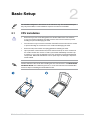
Chapter 2: Basic Setup
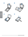
2.1 CPU installation ..........................................................................................2-1
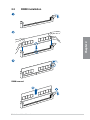
2.2 DIMM installation ........................................................................................2-3
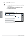
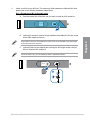
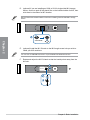
2.3 M.2 module installation ............................................................................2-4
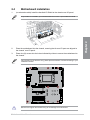
2.4 Motherboard installation ...........................................................................2-9
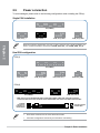
2.5 Power connection ....................................................................................2-10
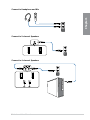
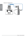
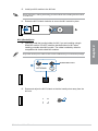
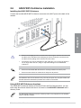
2.6 ASUS WiFi Q-Antenna installation .........................................................2-11
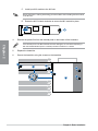
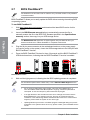
2.7 BIOS FlashBack™ ....................................................................................2-12
2.8 Starting up for the first time ....................................................................2-13
2.9 Turning off the computer ........................................................................2-13
Chapter 3: BIOS and RAID Support
3.1 Knowing UEFI BIOS ................................................................................... 3-1
3.2 ASUS EZ Flash Utility ................................................................................3-2
3.3 ASUS CrashFree BIOS 3 ............................................................................3-3
3.4 RAID configurations ..................................................................................3-4
Appendix
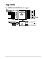
Pro WS TRX50-SAGE WIFI block diagram ............................................................ A-1
General Notices ....................................................................................................... A-2
Notices for Wi-Fi model .......................................................................................... A-5
Warranty ................................................................................................................. A-13
ASUS contact information .................................................................................... A-15
Service and Support ............................................................................................. A-15
Product Register ................................................................................................... A-15

iv
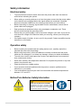
Safety information
Electrical safety
• To prevent electrical shock hazard, disconnect the power cable from the electrical
outlet before relocating the system.
• When adding or removing devices to or from the system, ensure that the power cables
for the devices are unplugged before the signal cables are connected. If possible,
disconnect all power cables from the existing system before you add a device.
• Before connecting or removing signal cables from the motherboard, ensure that all
power cables are unplugged.
• Seek professional assistance before using an adapter or extension cord. These
devices could interrupt the grounding circuit.
• Ensure that your power supply is set to the correct voltage in your area. If you are not
sure about the voltage of the electrical outlet you are using, contact your local power
company.
• If the power supply is broken, do not try to fix it by yourself. Contact a qualified service
technician or your retailer.
Operation safety
• Before installing the motherboard and adding devices on it, carefully read all the
manuals that came with the package.
• Before using the product, ensure all cables are correctly connected and the power
cables are not damaged. If you detect any damage, contact your dealer immediately.
• To avoid short circuits, keep paper clips, screws, and staples away from connectors,
slots, sockets and circuitry.
• Avoid dust, humidity, and temperature extremes. Do not place the product in any area
where it may become wet.
• Place the product on a stable surface.
• If you encounter technical problems with the product, contact a qualified service
technician or your retailer.
• Your motherboard should only be used in environments with ambient temperatures
between 10°C and 35°C.
Button/Coin Batteries Safety Information
WARNING
KEEP OUT OF REACH OF CHILDREN
Swallowing can lead to chemical burns,
perforation of soft tissue, and death. Severe
burns can occur within 2 hours of ingestion.
Seek medical attention immediately.

v
About this guide
This user guide contains the information you need when installing and configuring the
motherboard.
How this guide is organized
This guide contains the following parts:
• Chapter 1: Product Introduction
This chapter describes the features of the motherboard and includes descriptions for
each part of the motherboard.
• Chapter 2: Basic Setup
This chapter lists the basic setup procedures for setting up your motherboard.
• Chapter 3: BIOS and RAID Support
This chapter tells how to boot into the BIOS, upgrade BIOS using the EZ Flash Utility
and support on RAID.
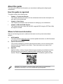
Where to find more information
Refer to the following sources for additional information and for product and software
updates.
1. ASUS website
The ASUS website (www.asus.com) provides updated information on ASUS hardware
and software products.
2. Optional documentation
Your product package may include optional documentation, such as warranty flyers,
that may have been added by your dealer. These documents are not part of the
standard package.
3. MyASUS
MyASUS offers a variety of support features such as helping to troubleshoot issues,
optimizing product performance, integrating ASUS software, and recovery drive
creation. Please visit https://www.asus.com/support for installation guide and FAQ.
MyASUS is only available on selected models, please check your motherboard’s
specifications summary to see if your motherboard supports MyASUS.

vi
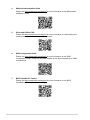
6. RAID Configuration Guide
Please visit https://www.asus.com/support for more information on the RAID
Configuration Guide. Please visit the AMD website for the latest information on RAID
configurations.
7. BIOS FlashBack™ Feature
Please visit https://www.asus.com/support for more information on the BIOS
FlashBack™ Feature.
4. Motherboard Installation Guide
Please visit https://www.asus.com/support for more information on the Motherboard
Installation Guide.
5. Driver and Utilities FAQ
Please visit https://www.asus.com/support for more information on downloading and
installing drivers and utilities for your motherboard.

vii
Conventions used in this guide
To ensure that you perform certain tasks properly, take note of the following symbols used
throughout this user guide.
CAUTION: Information to prevent damage to the components and injuries to
yourself when trying to complete a task.
IMPORTANT: Instructions that you MUST follow to complete a task.
NOTE: Tips and additional information to help you complete a task.

viii
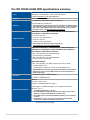
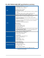
Pro WS TRX50-SAGE WIFI specifications summary
CPU
AMD Socket sTR5 for Ryzen™ Threadripper™ PRO 7000 WX-Series
and Ryzen™ Threadripper™ 7000 Series Processors*
* Refer to www.asus.com for CPU support list.
Chipset AMD TRX50 Chipset
Memory
4 x DIMM slots, DDR5, ECC Registered Memory*
4 Channel Memory Architecture
* Supported memory types, data rate (speed), and number of DRAM modules
vary depending on the CPU and memory configuration, for more information
please refer to CPU/Memory Support list under the Support tab of product
information site or visit https://www.asus.com/support/.
Expansion Slots
AMD Ryzen™ Threadripper™ PRO 7000 WX-Series and Ryzen™
Threadripper™ 7000 Series Processors
2 x PCIe 5.0 x16 slots
1 x PCIe 5.0 x16 slot(x8 mode)
1 x PCIe 4.0 x16 slot
1 x PCIe 4.0 x16 slot(x4 mode)
* Please check PCIe bifurcation table on support site
(https://www.asus.com/support/FAQ/1037507/).
Storage
Supports 3 x M.2 slots, 1 x SlimSAS port, 4 x SATA 6Gb/s ports
AMD Ryzen™ Threadripper™ PRO 7000 WX-Series and Ryzen™
Threadripper™ 7000 Series Processors
- M.2_1 slot (Key M), type 2242/2260/2280
(supports PCIe 5.0 x4 mode)
- M.2_2 slot (Key M), type 2242/2260/2280
(supports PCIe 5.0 x4 mode)
AMD TRX50 Chipset
- M.2_3 slot (Key M), type 2280 (supports PCIe 4.0 x4 mode)
- 4 x SATA 6Gb/s ports
- 1 x SlimSAS slot supports PCIe 4.0 x4 mode NVMe device
* AMD RAIDXpert2 Technology supports both PCIe RAID 0/1/5/10 and SATA
RAID 0/1/5/10. Please visit the AMD website for the latest information on
RAID configurations.
Ethernet 1 x Marvell® AQtion 10Gb Ethernet
1 x Intel® 2.5Gb Ethernet
Wireless & Bluetooth®
Wi-Fi 7*
2x2 Wi-Fi 7 (802.11be)**
Supports 2.4/5/6GHz frequency band***
Support Wi-Fi 7 160MHz bandwidth, up to 2.8Gbps transfer rate.
Bluetooth® v5.4****
* Compatible with Windows 11 or later.
** Wi-Fi 7 MLO(Multi-link Operation) full functions support will be ready in
Windows 11 2024 Platform (Windows 11 24H2) or later.
*** Wi-Fi 6GHz frequency band and bandwidth regulatory may vary between
countries.
**** The Bluetooth® version may vary, please refer to the Wi-Fi module
manufacturer’s website for the latest specifications.
(continued on the next page)

ix
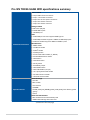
Pro WS TRX50-SAGE WIFI specifications summary
USB
Rear USB (Total 9 ports)
1 x USB 20Gbps port (1 x USB Type-C®)
6 x USB 10Gbps ports (6 x Type-A)
2 x USB 2.0 ports (2 x Type-A)
Front USB (Total 7 ports)
1 x USB 20Gbps connector (supports USB Type-C® with up to 27W PD/
QC4+)
1 x USB 5Gbps header supports 2 additional USB 5Gbps ports
2 x USB 2.0 headers support 4 additional USB 2.0 ports
Audio
Realtek ALC1220P Surround Sound High Definition Audio CODEC*
- Impedance sense for front and rear headphone outputs
- Internal audio Amplifier to enhance the highest quality sound for
headphone and speakers
- Supports: Jack-detection, Multi-streaming, Front Panel Jack-retasking
- High quality 120 dB SNR stereo playback output and 113 dB SNR
recording input (Line-in)
- Supports up to 32-Bit/192 kHz playback*
Audio Features
- Audio Shielding
- Rear optical S/PDIF out port
- Dedicated audio PCB layers
- Unique de-pop circuit
* A chassis with an HD audio module in the front panel is required to support
5.1 Surround Sound audio output.
* This motherboard will only support up to 5.1 Surround Sound due to the
number of audio ports available on this motherboard,
Back Panel I/O Ports
1 x USB 20Gbps port (1 x USB Type-C®)
6 x USB 10Gbps ports (6 x Type-A)
2 x USB 2.0 port (2 x Type-A)
1 x Wi-Fi Module
1 x Marvell® AQtion 10Gb Ethernet port
1 x Intel® 2.5Gb Ethernet port
2 x Audio jacks
1 x Optical S/PDIF out port
1 x BIOS FlashBack™ button
1 x Clear CMOS button
Internal I/O Connectors
Fan and Cooling related
1 x 4-pin CPU Fan header
1 x 4-pin CPU OPT Fan header
1 x W_PUMP+ header
4 x 4-pin Chassis Fan headers
2 x 4-pin VRM Heatsink Fan header (with VRM FAN onboard)
(continued on the next page)

x
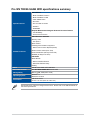
Pro WS TRX50-SAGE WIFI specifications summary
Internal I/O connectors
Power related
2 x 24-pin Main Power connectors
2 x 8-pin +12V Power connectors
2 x 8-pin PCIe to CPU power connectors
1 x 6-pin PCIe Power connector
1 x 8-pin PCIe Power connector
Storage related
3 x M.2 slots (Key M)
4 x SATA 6Gb/s ports
1 x SlimSAS port
USB
1 x USB 20Gbps connector supports USB Type-C®
1 x USB 5Gbps header supports 2 additional USB 5Gbps ports
2 x USB 2.0 headers support 4 additional USB 2.0 ports
Miscellaneous
1 x BMC header
1 x COM Port header
1 x USB4® header
1 x FlexKey button
1 x Front Panel Audio header (F_AUDIO)
7 x ProbeIt Measurement Points
1 x Start button
1 x Safe Boot button
1 x ReTry button
1 x LN2 Mode jumper
1 x Slow Mode switch
1 x SPI TPM header (14-1pin)
1 x 10⁻¹ pin System Panel header
1 x Chassis Intrusion header
1 x Thermal Sensor header
Special Features
ASUS Q-Design
- Q-Code
- M.2 Q-Latch
- Q-Connector
- Q-DIMM
- Q-LED (CPU [red], DRAM [yellow], VGA [white], Boot Device [yellow
green])
- Q-Slot
ASUS Thermal Solution
- M.2 heatsink and onboard thermal pads
- VRM heatsink design with active fans
(continued on the next page)

xi
Pro WS TRX50-SAGE WIFI specifications summary
Special Features
ASUS EZ DIY
- BIOS FlashBack™ button
- BIOS FlashBack™ LED
- Clear CMOS button
- ProCool II
- Pre-mounted I/O shield
- SafeSlot
- SafeDIMM
Bespoke Motherboard Design & Business Focused Features
- 24/7 Reliability
- Overcurrent Protection
Software Features
ASUS Exclusive Software
Armoury Crate
- Fan Xpert 4
ASUS CPU-Z
IT Management software supported
- ASUS Control Center Express(ACCE)
Adobe Creative Cloud (Free Trial)
Norton 360 Deluxe (60 Days Free Trial)
WinRAR (40 Days Free Trial)
UEFI BIOS
ASUS EZ DIY
- ASUS CrashFree BIOS 3
- ASUSTeK. EzFlash Utility
FlexKey
BIOS 256 Mb Flash ROM, UEFI AMI BIOS
BIOS CAP Filename Pro WS TRX50-SAGE WIFI: A5497.CAP
Manageability WOL by PME, PXE (UEFI mode)
Operating System Windows® 11
Windows® 10 64-bit
Form Factor CEB Form Factor
12 inch x 11 inch (30.5 cm x 28.0 cm)
Specifications are subject to change without notice. Please refer to the ASUS website for
the latest specifications.

xii
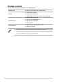
Package contents
Check your motherboard package for the following items.
Motherboard Pro WS TRX50-SAGE WIFI motherboard
Cables
2 x SATA 6Gb/s cables
1 x Thermistor cable pack
1 x CPU 8-pin to PCIe 8-pin adapter cable package
Miscellaneous
1 x ASUS WiFi Q-Antenna
1 x M.2 Q-Latch package(2 in 1)
2 x M.2 Rubber Packages
1 x Q-connector
Documentation 1 x ACC Express Activation Key Card
1 x Quick start guide
• If any of the above items is damaged or missing, contact your retailer.
• Items not listed in the Package contents list above are purchased separately and do
not come bundled with your motherboard package.

Motherboard User Manual 1-1
Chapter 1
Product Introduction
1
Chapter 1: Product Introduction
• Unplug the power cord from the wall socket before touching any component.
• Before handling components, use a grounded wrist strap or touch a safely grounded
object or a metal object, such as the power supply case, to avoid damaging them due
to static electricity.
• Hold components by the edges to avoid touching the ICs on them.
• Whenever you uninstall any component, place it on a grounded antistatic pad or in
the bag that came with the component.
• Before you install or remove any component, ensure that the power supply is
switched off or the power cord is detached from the power supply. Failure to do so
may cause severe damage to the motherboard, peripherals, or components.
• The pin definitions in this chapter are for reference only. The pin names depend on
the location of the header/jumper/connector.
• The illustrations for this chapter are for reference only. The WiFi module is only
available on selected models.
1.1 Before you proceed
Take note of the following precautions before you install motherboard components or
change any motherboard settings.

1-2 Chapter 1: Product Introduction
Chapter 1
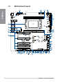
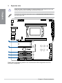
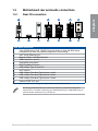
1.2 Motherboard layout

Motherboard User Manual 1-3
Chapter 1
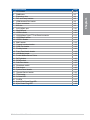
Layout contents Page
1. CPU socket 1-4
2. DIMM slots 1-5
3. Expansion slots 1-6
4. Fan and Pump headers 1-8
5. VRM Heatsink Fan header 1-8
6. Power connectors 1-9
7. M.2 slot 1-9
8. SATA 6Gb/s port 1-10
9. SlimSAS port 1-10
10. USB4® header 1-10
11. USB 20Gbps Type-C® Front Panel connector 1-11
12. USB 5Gbps header 1-11
13. USB 2.0 header 1-11
14. BMC header 1-12
15. Chassis Intrusion header 1-12
16. COM Port header 1-12
17. FlexKey button 1-12
18. Front Panel Audio header 1-13
19. LN2 Mode jumper 1-13
20. ProbeIt Measurement Points 1-14
21. ReTry button 1-15
22. RSVD switch 1-15
23. Safe Boot button 1-15
24. Slow Mode switch 1-15
25. Start button 1-16
26. System Panel header 1-16
27. Thermal Sensor header 1-16
28. TPM header 1-17
29. Q-Code LED 1-17
30. Q-LEDs 1-17
31. 8-pin PCIe Power Plug LED 1-18
32. 8-pin Power Plug LED 1-18

1-4 Chapter 1: Product Introduction
Chapter 1
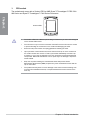
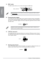
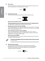
1. CPU socket
The motherboard comes with a Socket sTR5 for AMD Ryzen™ Threadripper™ PRO 7000
WX-Series and Ryzen™ Threadripper™ 7000 Series Processors.
Socket sTR5
• The Socket sTR5 has a different pinout design. Ensure that you use a CPU designed
for the Socket sTR5 socket.
• The CPU fits in only one correct orientation. DO NOT force the CPU into the socket
to prevent bending the connectors on the socket and damaging the CPU.
• Ensure that all power cables are unplugged before installing the CPU.
• Upon purchase of the motherboard, ensure that the PnP cap is on the socket and
the socket contacts are not bent. Contact your retailer immediately if the PnP cap
is missing, or if you see any damage to the PnP cap/socket contacts/motherboard
components. ASUS will shoulder the cost of repair only if the damage is shipment/
transit-related.
• Keep the cap after installing the motherboard. ASUS will process Return
Merchandise Authorization (RMA) requests only if the motherboard comes with the
cap on the socket.
• The product warranty does not cover damage to the socket contacts resulting from
incorrect CPU installation/removal, or misplacement/loss/incorrect removal of the
PnP cap.

Motherboard User Manual 1-5
Chapter 1
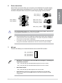
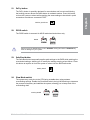
2. DIMM slots
The motherboard comes with Dual Inline Memory Modules (DIMM) slots designed for
DDR5 (Double Data Rate 5) memory modules.
A DDR5 memory module is notched differently from a DDR, DDR2, DDR3, or DDR4
module. DO NOT install a DDR, DDR2, DDR3, or DDR4 memory module to the DDR5
slot.
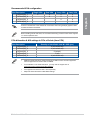
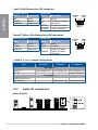
Recommended memory configurations
Slot A1 C1 E1 G1
1-DIMM V
2-DIMM V V
4-DIMM V V V V
Memory configurations
You may install ECC registered DDR5 DIMMs into the DIMM sockets.
• AMD Ryzen™ processors support ECC registered memory.
• The default memory operation frequency is dependent on its Serial Presence Detect
(SPD), which is the standard way of accessing information from a memory module.
Under the default state, some memory modules for overclocking may operate at a
lower frequency than the vendor-marked value.
• For system stability, use a more efficient memory cooling system to support a full
memory load or overclocking condition.
• Always install the DIMMS with the same CAS Latency. For an optimum compatibility,
we recommend that you install memory modules of the same version or data code
(D/C) from the same vendor. Check with the vendor to get the correct memory
modules.
• Visit the ASUS website for the latest QVL.

1-6 Chapter 1: Product Introduction
Chapter 1
3. Expansion slots
Unplug the power cord before adding or removing expansion cards. Failure to do so may
cause you physical injury and damage motherboard components.
To install a PCIe expansion card, please refer to the Motherboard Installation Guide on
the ASUS support site.
Please refer to the following tables for the recommended VGA configuration and PCIe
bifurcation configuration.

Motherboard User Manual 1-7
Chapter 1
Recommended VGA configuration
Slot Description Single VGA Dual VGA 3-way VGA 4-way VGA
1 PCIEX16(G5)_1 V V V V
2 PCIEX16(G5)_2 V V V
3 PCIEX16(G5)_3 V V
5 PCIEX16(G4)_2 V
Connect a chassis fan to the chassis fan connectors when using multiple graphics cards
for better thermal environment.
When installing a dual VGA card, we recommend selecting a chassis case which supports
7 or more expansion slots
PCIe bifurcation & M.2 settings in PCIe x16 slots (from CPU)
Slot Description Quantity of identifiable Intel M.2 SSD (pcs)
1 PCIEX16(G5)_1 4 (x4+x4+x4+x4)
2 PCIEX16(G5)_2 4 (x4+x4+x4+x4)
3 PCIEX16(G5)_3 2 (x4+x4)
4 PCIEX16(G4)_1 1 (x4)
5 PCIEX16(G4)_2 4 (x4+x4+x4+x4)
• Additional PCIe bifurcation and M.2 settings for RAID function are also supported
when a Hyper M.2 x16 series card is installed.
• For full details on the PCIe bifurcation, you may visit the support site at
https://www.asus.com/support/FAQ/1037507/.
• The Hyper M.2 X16 series card is sold separately.
• Adjust the PCIe bifurcation under BIOS settings.

1-8 Chapter 1: Product Introduction
Chapter 1
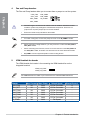
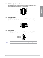
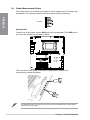
4. Fan and Pump headers
The Fan and Pump headers allow you to connect fans or pumps to cool the system.
CPU_FAN
CPU_OPT
CHA_FAN1
CHA_FAN2
CHA_FAN3
CHA_FAN4
W_PUMP+
• DO NOT forget to connect the fan cables to the fan headers. Insufficient air flow
inside the system may damage the motherboard components. These are not
jumpers! Do not place jumper caps on the fan headers!
• Ensure the cable is fully inserted into the header.
• For water cooling kits, connect the pump connector to the W_PUMP+ header.
• When connecting a single CPU fan, you may connect it to either the CPU_FAN or
CPU_OPT header.
• When connecting two CPU fans, ensure to connect the fans to the CPU_FAN and
the CPU_OPT header, and make sure both fans are the same brand and model.
• W_PUMP+ function support depends on water cooling device.
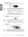
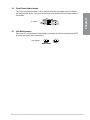
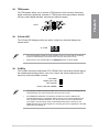
5. VRM Heatsink fan header
The VRM Heatsink fan header is for connecting the VRM Heatsink fan on the
integrated heatsink.
VRM_HS_FAN1
VRM_HS_FAN2
The VRM Heatsink fan header is pre-connected to the onboard VRM Heatsink fan.
Header Max. Current Max. Power Default Speed Shared Control
CPU_FAN 3A 36W Q-Fan Controlled A
CPU_OPT 3A 36W Q-Fan Controlled A
CHA_FAN1 3A 36W Q-Fan Controlled -
CHA_FAN2 3A 36W Q-Fan Controlled -
CHA_FAN3 3A 36W Q-Fan Controlled -
CHA_FAN4 3A 36W Q-Fan Controlled -
W_PUMP+ 3A 36W Full Speed -
La page est en cours de chargement...
La page est en cours de chargement...
La page est en cours de chargement...
La page est en cours de chargement...
La page est en cours de chargement...
La page est en cours de chargement...
La page est en cours de chargement...
La page est en cours de chargement...
La page est en cours de chargement...
La page est en cours de chargement...
La page est en cours de chargement...
La page est en cours de chargement...
La page est en cours de chargement...
La page est en cours de chargement...
La page est en cours de chargement...
La page est en cours de chargement...
La page est en cours de chargement...
La page est en cours de chargement...
La page est en cours de chargement...
La page est en cours de chargement...
La page est en cours de chargement...
La page est en cours de chargement...
La page est en cours de chargement...
La page est en cours de chargement...
La page est en cours de chargement...
La page est en cours de chargement...
La page est en cours de chargement...
La page est en cours de chargement...
La page est en cours de chargement...
La page est en cours de chargement...
La page est en cours de chargement...
La page est en cours de chargement...
La page est en cours de chargement...
La page est en cours de chargement...
La page est en cours de chargement...
La page est en cours de chargement...
La page est en cours de chargement...
La page est en cours de chargement...
La page est en cours de chargement...
La page est en cours de chargement...
La page est en cours de chargement...
La page est en cours de chargement...
La page est en cours de chargement...
La page est en cours de chargement...
La page est en cours de chargement...
La page est en cours de chargement...
La page est en cours de chargement...
La page est en cours de chargement...
-
 1
1
-
 2
2
-
 3
3
-
 4
4
-
 5
5
-
 6
6
-
 7
7
-
 8
8
-
 9
9
-
 10
10
-
 11
11
-
 12
12
-
 13
13
-
 14
14
-
 15
15
-
 16
16
-
 17
17
-
 18
18
-
 19
19
-
 20
20
-
 21
21
-
 22
22
-
 23
23
-
 24
24
-
 25
25
-
 26
26
-
 27
27
-
 28
28
-
 29
29
-
 30
30
-
 31
31
-
 32
32
-
 33
33
-
 34
34
-
 35
35
-
 36
36
-
 37
37
-
 38
38
-
 39
39
-
 40
40
-
 41
41
-
 42
42
-
 43
43
-
 44
44
-
 45
45
-
 46
46
-
 47
47
-
 48
48
-
 49
49
-
 50
50
-
 51
51
-
 52
52
-
 53
53
-
 54
54
-
 55
55
-
 56
56
-
 57
57
-
 58
58
-
 59
59
-
 60
60
-
 61
61
-
 62
62
-
 63
63
-
 64
64
-
 65
65
-
 66
66
-
 67
67
-
 68
68


Asus Pro WS TRX50-SAGE WIFI Manuel utilisateur
- Catégorie
- Cartes mères
- Taper
- Manuel utilisateur
dans d''autres langues
Documents connexes
-
Asus ROG MAXIMUS Z790 FORMULA Manuel utilisateur
-
-
-
-
-
-
-
-
Asus PRIME B650M-A AX Mode d'emploi
-