
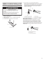
INSTALLATION INSTRUCTIONS
30" (76.2 CM) FREESTANDING ELECTRIC RANGES
INSTRUCTIONS D’INSTALLATION POUR CUISINIÈRES
ÉLECTRIQUES AUTOPORTANTES DE 30" (76,2 cm)
INSTRUCCIONES DE INSTALACIÓN ESTUFAS ELÉCTRICAS
INDEPENDIENTES DE 30" (76,2 cm)
Table of Contents
IMPORTANT:
Save for local electrical inspector's use.
IMPORTANT :
Conserver ces instructions à l’usage de l’inspecteur des installations électriques local.
IMPORTANTE:
Guarde para tener a disposición del inspector de electricidad local.
W11085337C
Table des matières
Índice
SEGURIDAD DE LA ESTUFA.......................................................32
REQUISITOS DE INSTALACIÓN .................................................33
Herramientas y piezas ................................................................33
Requisitos de ubicación .............................................................33
Requisitos eléctricos — EE. UU. únicamente ...........................35
Requisitos eléctricos – Solo en Canadá ....................................36
INSTRUCCIONES DE INSTALACIÓN .........................................37
Desempaque la estufa ...............................................................37
Instalación del soporte antivuelco .............................................38
Verify Anti-Tip Bracket Is Installed and Engaged ......................13
Level Range ................................................................................14
Warming Drawer or Premium StorageDrawer ...........................14
Storage Drawer ..........................................................................15
Oven Door ..................................................................................15
Complete Installation .................................................................15
Moving the Range ......................................................................16
Raccordement électrique – É.-U. seulement .............................24
Vérifier que la bride antibasculement est bien installée et
engagée ......................................................................................28
Réglage de l’aplomb de la cuisinière .........................................29
Tiroir-réchaud ou tiroir de remisage de qualité supérieure ........ 29
Tiroir de remisage ....................................................................... 30
Porte du four ..............................................................................30
Terminer l’installation ..................................................................30
Déplacement de la cuisinière .....................................................31
SÉCURITÉ DE LA CUISINIÈRE ...................................................17
EXIGENCES D’INSTALLATION ...................................................18
Outils et pièces ...........................................................................18
Exigences d’emplacement .........................................................18
Spécifications électriques – É.-U. seulement ............................20
Spécifications électriques ..........................................................21
INSTRUCTIONS D’INSTALLATION .............................................22
Déballage de la cuisinière ..........................................................22
Installation de la bride antibasculement ....................................23
Conexión eléctrica — EE. UU. únicamente ...............................39
Verifique que el soporte antivuelco esté instalado y
enganchado ...............................................................................43
Nivelación de la estufa ...............................................................44
Cajón de calentamiento o cajón de
almacenamiento premium .........................................................44
Cajón de almacenamiento .........................................................45
Puerta del horno ......................................................................... 45
Completar la instalación ............................................................45
Cómo mover la estufa ................................................................46
RANGE SAFETY .............................................................................2
INSTALLATION REQUIREMENTS ................................................. 3
Tools and Parts .............................................................................3
Location Requirements ................................................................3
Electrical Requirements — U.S.A. Only .......................................5
Electrical Requirements - Canada Only .......................................7
INSTALLATION INSTRUCTIONS ................................................... 7
Unpack Range..............................................................................7
Install Anti-Tip Bracket .................................................................8
Electrical Connection — U.S.A. Only ........................................... 9

2
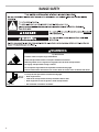
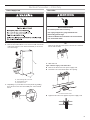
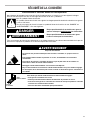
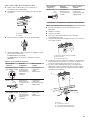
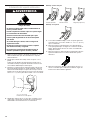
RANGE SAFETY
Tip Over Hazard
A child or adult can tip the range and be killed.
Install anti-tip bracket to floor or wall per installation instructions.
Slide range back so rear range foot is engaged in the slot of the anti-tip bracket.
Re-engage anti-tip bracket if range is moved.
Do not operate range without anti-tip bracket installed and engaged.
Failure to follow these instructions can result in death or serious burns to children and adults.
Anti-Tip
Bracket
To verify the anti-tip bracket is installed and engaged:
•Slide range forward.
•Look for the anti-tip bracket securely attached to floor or wall.
•Slide range back so rear range foot is under anti-tip bracket.
•See installation instructions for details.
Range Foot
WARNING

3
INSTALLATION REQUIREMENTS
Tools and Parts
Gather the required tools and parts before starting installation.
Read and follow the instructions provided with any tools listed
here.
Tools needed
■Tape measure
■Flat-blade screwdriver
■Phillips screwdriver
■Level
■Hammer
■Hand or electric drill
■Wrench or pliers
■Marker or pencil
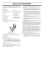
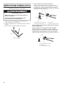
Parts supplied
Check that all parts are included.
■3 - 10-32 hex nuts (attached to terminal block)
■3 - Terminal lugs
A. Anti-tip bracket
B. #12 x 15⁄8" (41 mm) screws (2)
■Anti-tip bracket must be securely mounted to floor or wall.
Thickness of flooring may require longer screws to anchor
bracket to floor.
Parts needed
If using a power supply cord kit:
■A UL listed power supply cord kit marked for use with
ranges. The cord should be rated at 250 volts minimum,
40 amps or 50 amps that is marked for use with nominal
1³⁄8" (3.5 cm) diameter connection opening and must end in
ring terminals or open-end spade terminals with upturned
ends.
■A UL listed strain relief.
Check local codes. Check existing electrical supply. See the
appropriate “Electrical Requirements” section.
It is recommended that all electrical connections be made by a
licensed, qualified electrical installer.
■Masking tape
■1/4" (6.4 mm) drive ratchet
■1/4" (6.4 mm) nut driver
■3/8" (9.5 mm) and 5/16"
(8 mm) nut driver
■1/8" (3.2 mm) drill bit
(for wood floors)
■Tin snips or large wire
cutters (for cutting ground
strap if necessary)
Location Requirements
IMPORTANT: Observe all governing codes and ordinances.
■It is the installer’s responsibility to comply with installation
clearances specified on the model/serial rating plate. The
model/serial rating plate is located on the frame behind a top
corner of the door or either side of the drawer.
■To eliminate the risk of burns or fire by reaching over the
heated surface units, cabinet storage space located above
the surface units should be avoided. If cabinet storage
is to be provided, the risk can be reduced by installing a
range hood or microwave hood combination that projects
horizontally a minimum of 5" (12.7 cm) beyond the bottom of
the cabinets.
■Cabinet opening dimensions that are shown must be used.
Given dimensions are minimum clearances.
■The anti-tip bracket must be installed. To install the anti-tip
bracket shipped with the range, see the “Install Anti-Tip
Bracket” section.
■Grounded electrical supply is required. See the appropriate
“Electrical Requirements” section.
IMPORTANT: To avoid damage to your cabinets, check with
your builder or cabinet supplier to make sure that the materials
used will not discolor, delaminate, or sustain other damage. This
oven has been designed in accordance with the requirements
of UL and CSA International and complies with the maximum
allowable wood cabinet temperatures of 194° (90°C).
Mobile Home Additional Installation Requirements
The installation of this range must conform to the Manufactured
Home Construction and Safety Standard, Title 24 CFR,
Part 3280 (formerly the Federal Standard for Mobile Home
Construction and Safety, Title 24, HUD Part 280). When such
standard is not applicable, use the Standard for Manufactured
Home Installations, ANSI A225.1/NFPA 501A or local codes.
Mobile home installations require:
■When this range is installed in a mobile home, it must be
secured per the instructions in this document.
■Four-wire power supply cord or cable must be used in a
mobile home installation. The appliance wiring will need to
be revised. See the “Electrical Connection - U.S.A. Only”
section.
A
B

4
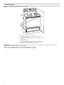
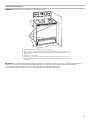
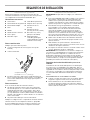
Product Dimensions
NOTE: The model may look different than the one pictured.
IMPORTANT: Range must be level after installation. Follow the instructions in the “Level Range” section. Using the cooktop as
a reference for leveling the range is not recommended.
*Range can be raised approximately 1" (2.5 cm) by adjusting the leveling legs.
**Front of door and drawer may extend further forward depending on styling.
A
B
C
D
F
E
A. 273/8" (69.5 cm) max. depth with handle
B. 461/2" (118.1 cm) overall height (max.) with leveling legs
screwed all the way in*
C. 36" (91.4 cm) cooktop height (max.) with leveling legs screwed
all the way in*
D. 297⁄8" (75.9 cm) width
E. 255⁄16" (64.3 cm) depth - back of range to front of cooktop**
F. Model/serial rating plate (located on the frame behind a top
corner of the door or either side of the drawer)

5
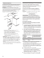
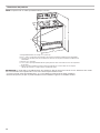
Cabinet Dimensions
Cabinet opening dimensions shown are for 25" (64.0 cm)
countertop depth, 24" (61.0 cm) base cabinet depth and
36" (91.4 cm) countertop height.
IMPORTANT: If installing a range hood or microwave hood
combination above the range, follow the range hood or
microwave hood combination installation instructions for
dimensional clearances above the cooktop surface.
A freestanding range may be installed next to combustible walls
with zero clearance.
A. 13" (33.0 cm) max. upper cabinet depth
B. 30" (76.2 cm) min. opening width
C. For minimum clearance to top of cooktop, see NOTE*
D. 30" (76.2 cm) min. opening width
E. Outlet - 8" (20.3 cm) to 22" (55.9 cm) from either cabinet,
5¹⁄2" (14.0 cm) max. from floor
F. Cabinet door or hinges should not extend into the cutout
* NOTE: 24" (61.0 cm) minimum when bottom of wood or
metal cabinet is covered by not less than 1/4" (6.4 mm) flame
retardant millboard covered with not less than No. 28 MSG
sheet steel, 0.015" (0.4 mm) stainless steel, 0.024" (0.6 mm)
aluminum or 0.020" (0.5 mm) copper.
30" (76.2 cm) minimum clearance between the top of the
cooking platform and the bottom of an uncovered wood or
metal cabinet.
Electrical Requirements — U.S.A. Only
If codes permit and a separate ground wire is used, it is
recommended that a qualified electrical installer determine that
the ground path and wire gauge are in accordance with local
codes.
Do not use an extension cord.
Be sure that the electrical connection and wire size are adequate
and in conformance with the National Electrical Code, ANSI/
NFPA 70-latest edition and all local codes and ordinances.
A copy of the above code standards can be obtained from:
National Fire Protection Association
1 Batterymarch Park
Quincy, MA 02169-7471
WARNING: Improper connection of the equipment-grounding
conductor can result in a risk of electric shock. Check with a
qualified electrician or service technician if you are in doubt as to
whether the appliance is properly grounded. Do not modify the
power supply cord plug. If it will not fit the outlet, have a proper
outlet installed by a qualified electrician.
Electrical Connection
To properly install your range, you must determine the type of
electrical connection you will be using and follow the instructions
provided for it here.
Range must be connected to the pr oper electrical voltage
and fr equency as specified on the model/serial rating plate.
The model/serial rating plate is located on the frame behind
a top corner of the door or either side of the drawer . Refer
to the figures in “Pr oduct Dimensions” in the “Location
Requirements” section.
This range is manufactur ed with the neutral terminal
connected to the cabinet. Use a 3-wire, UL Listed, 40 or
50 amp power supply cor d (pigtail) (see the following Range
Rating chart). If local codes do not permit ground thr ough
the neutral, use a 4-wire power supply cord rated at
250 V, 40 or 50 amps and investigated for use with ranges.
Range Rating* Specified Rating
of Power Supply
Cord Kit and Circuit
Protection
120/240 Volts 120/208 Volts Amps
8.8-16.5 KW 7.8 - 12.5 KW 40 or 50**
16.6-22.5 KW 12.6 - 18.5 KW 50
* The NEC calculated load is less than the total connected load
listed on the model/serial rating plate.
** If connecting to a 50 amp circuit, use a 50 amp rated cord
with kit. For 50-amp rated cord kits, use kits that specify use
with a nominal 1³⁄8" (34.9 mm) diameter connection opening.
■A circuit breaker is recommended.
■The range can be connected directly to the circuit breaker
box (or fused disconnect) through flexible or nonmetallic
sheathed, copper, or aluminum cable. See the “Electrical
Connection — U.S.A. Only” section.
■Allow 2 to 3 ft (61.0 to 91.4 cm) of slack in the line so that the
range can be moved if servicing is ever necessary.
A
B
D
F
E
C

6
■A UL listed conduit connector must be provided at each end
of the power supply cable (at the range and at the junction
box).
■Wire sizes and connections must conform with the rating of
the range.
■The wiring diagram is located on the Tech Sheet.
■The Tech Sheet is located on the back of the range inside a
clear plastic bag.
If connecting to a 4-wire system:
This range is manufactured with the ground connected to the
neutral by a link. The ground must be revised so the green
ground wire of the 4-wire power supply cord is connected to the
cabinet. See the “Electrical Connection — U.S.A. Only” section.
Grounding through the neutral conductor is prohibited for new
branch-circuit installations (1996 NEC); mobile homes; and
recreational vehicles, or an area where local codes prohibit
grounding through the neutral conductor.
When a 4-wire receptacle of NEMA Type 14-50R is used, a
matching UL listed, 4-wire, 250 volt, 40 or 50 amp, range
power supply cord (pigtail) must be used. This cord contains
4 copper conductors with ring terminals or open-end spade
terminals with upturned ends, terminating in a NEMA Type
14-50P plug on the supply end.
The fourth (grounding) conductor must be identified by a green
or green/yellow cover and the neutral conductor by a white
cover. Cord should be Type SRD or SRDT with a UL listed strain
relief and be at least 4 ft (1.22 m) long.
4-wire receptacle (14-50R)
The minimum conductor sized for the copper 4-wire power
cord are:
40 amp circuit
2 No.-8 conductors
1 No.-10 white neutral
1 No.-8 green grounding
If connecting to a 3-wire system:
Local codes may permit the use of a UL listed, 3-wire,
250 V, 40 or 50 amp range power supply cord (pigtail). This
cord contains 3 copper conductors with ring terminals or
open-end spade terminals with upturned ends, terminating in a
NEMA Type 10-50P plug on the supply end. Connectors on the
appliance end must be provided at the point the power supply
cord enters the appliance. This uses a 3-wire receptacle of
NEMA Type 10-50R.
3-wire receptacle (10-50R)
■

7
INSTALLATION INSTRUCTIONS
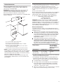
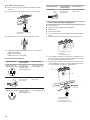
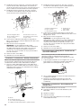
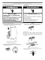
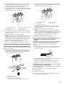
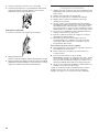
Unpack Range
1. Remove shipping materials, tape, and film from range.
2. Remove oven racks and parts package from inside oven.
3. Do not remove the shipping base at this time.
A. Shipping base
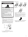
4. On Ranges Equipped with a Storage Drawer:
Remove the storage drawer. See the “Storage Drawer”
section. Use a 1/4" (6.4 mm) drive ratchet to lower the rear
leveling legs one-half turn. Use a wrench or pliers to lower
front leveling legs one-half turn.
A. 1/4" (6.4 mm) drive ratchet
B. Rear leveling leg
C. Wrench or pliers
D. Front leveling leg
On Ranges Equipped with a Warming Drawer or Premium
Storage Drawer:
On ranges equipped with a warming drawer or premium storage
drawer, the rear legs cannot be accessed by removing the
warming drawer or premium storage drawer. It will be necessary
to adjust the rear legs from outside the range. Use wrench or
pliers to lower the front and rear leveling legs one-half turn.
A. Rear leveling leg
B. Wrench or pliers
C. Front leveling leg
WARNING
Excessive Weight Hazard
Use two or more people to move and install range.
Failure to do so can result in back or other injury.
A
C
D
A
B
B
C
A
Electrical Requirements - Canada Only
If codes permit and a separate ground wire is used, it is
recommended that a qualified electrical installer determine that
the ground path is adequate and wire gauge are in accordanc
with local codes.
Be sure that the electrical connection and wire size are adequate
and in conformance with CSA Standard C22.1, Canadian
Electrical Code, Part 1 - latest edition, and all local codes and
ordinances.
A copy of the above code standards can be obtained from:
Canadian Standards Association
178 Rexdale Blvd.
Toronto, ON M9W 1R3 CANADA
■Check with a qualified electrical installer if you are not sure
the range is properly grounded.
Range Ratings* Specified Rating of Power
Supply Cord Kit and Circuit
Protection
120/240 Volts 120/208
Volts Amps
8.8 - 16.5 KW
16.6 - 22.5 KW
7.8 -
12.5 KW
12.6 -
18.5 KW
40 or 50**
50
The NEC calculated load is less than the total connected load
listed on the model/serial/rating plate.
**If connecting to a 50 amp circuit, use a 50 amp rated cord with
kit. For 50 amp rated cord kits, use kits that specify use with a
nominal 1³⁄8" (34.9 mm) diameter connection opening.
■A time-delay fuse or circuit breaker is recommended.
■This range is equipped with a CSA International Certified
Power Cord intended to be plugged into a standard 14-50R
wall receptacle. Be sure the wall receptacle is within reach of
range’s final location.
■Do not use an extension cord.
WARNING
Electrical Shock Hazard
Electrically ground range.
Failure to do so can result in death, fire, or
electrical shock.

8
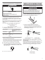
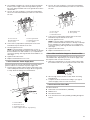
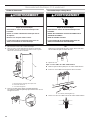
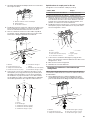
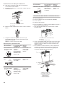
Install Anti-Tip Bracket
1. Remove the anti-tip bracket from where it is taped inside the
storage drawer or warming drawer.
2. Determine which mounting method to use: floor or wall.
If you have a stone or masonry floor, you can use the wall
mounting method. If you are installing the range in a mobile
home, you must secure the range to the floor.
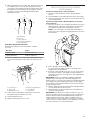
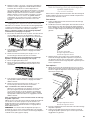
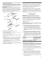
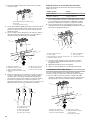
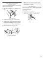
3. Determine and mark centerline of the cutout space. The
mounting can be installed on either the left side or right side
of the cutout. Position mounting bracket against the wall in
the cutout so that the V-notch of the bracket is 129⁄16"
(31.9 cm) from centerline as shown.
A. 129⁄16" (31.9 cm)
B. Bracket V-notch
4. Drill two 1/8" (3 mm) holes that correspond to the bracket
holes of the determined mounting method. See the following
illustrations.
Floor Mounting
Rear position Front position Diagonal (2 options)
Wall Mounting
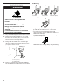
5. Using the Phillips screwdriver, mount anti-tip bracket to
the wall or floor with the two #12 x 15⁄8" (41 mm) screws
provided.
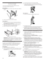
6. Move range close enough to opening to allow for final
electrical connections. Remove shipping base, cardboard, or
hardboard from under range.
7. Move range into its final location, making sure rear leveling
leg slides into anti-tip bracket.
8. Move range forward onto shipping base, cardboard, or
hardboard to continue installing the range using the following
installation instructions.
WARNING
Tip Over Hazard
A child or adult can tip the range and be killed.
Install anti-tip bracket to floor or wall per installation
instructions.
Slide range back so rear range foot is engaged in the
slot of the anti-tip bracket.
Re-engage anti-tip bracket if range is moved.
Do not operate range without anti-tip bracket installed
and engaged.
Failure to follow these instructions can result in death
or serious burns to children and adults.
Centerline
B
A

9
Electrical Connection — U.S.A. Only
Power Supply Cord
1. Disconnect power.
2. Remove the terminal block cover screws located on the back
of the range. Pull the cover down and toward you to remove
cover from range.
A. Two mounting tabs each side
B. Terminal block cover
C. Hex-head screws
A. UL Listed strain relief
■Tighten strain relief screw against the power supply cord.
3. Depending on your model, remove the plastic tag holding
three 10-32 hex nuts from the middle post of the terminal
block.
WARNING
Electrical Shock Hazard
Disconnect power before servicing.
Use 8 gauge copper or 6 gauge aluminum wire.
Electrically ground range.
Failure to follow these instructions can result in death,
fire, or electrical shock.
A
B
C
4. Add strain relief.
Style 1: Power supply cord strain relief
■Remove the knockout for the power supply cord.
■Assemble a UL Listed strain relief in the opening.
A
OR
Remove the top 10-32 hex nut from each of the 3 terminal
blocks and set aside.
Direct Wire
REMOVE PLASTIC TAG AND
PLACE NUTS ONTO THE BLOCKS

10
Style 2: Direct wire strain relief
■Remove the knockout as needed for the flexible conduit
connection.
■Assemble a UL listed conduit connector in the opening.
A. Removable retaining nut
B. Conduit
■Tighten strain relief screw against the flexible conduit.
5. Complete installation following instructions for your type of
electrical connection:
4-wire (recommended)
3-wire (if 4-wire is not available)
Electrical Connection Options
If your home has: And you will be
connecting to: Go to Section:
4-wire receptacle
(NEMA type 14-50R) A UL Listed,
250 volt minimum,
40 amp, range
power supply cord
4-wire connection:
Power supply cord
4-wire direct A circuit breaker
box or fused
disconnect
4-wire connection:
Direct wire
3-wire receptacle
(NEMA type 10-50R) A UL Listed,
250 volt minimum,
40 amp, range
power supply cord
3-wire connection:
Power supply cord
If your home has: And you will be
connecting to: Go to Section:
3-wire direct A circuit breaker
box or fused
disconnect
3-wire connection:
Direct wire
4-wire connection: Power Supply Cord
Use this method for:
■New branch-circuit installations (1996 NEC)
■Mobile homes
■Recreational vehicles
■In an area where local codes prohibit grounding through the
neutral
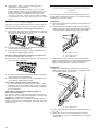
1. Part of metal ground strap must be cut out and removed.
A. Metal ground strap
B. Discard
C. Ground-link screw
2. Use a Phillips screwdriver to remove the ground-link screw
from the back of the range. Save the ground-link screw and
the end of the ground link under the screw.
3. Feed the power supply cord through the strain relief on the
cord/conduit plate on bottom of range. Allow enough slack
to easily attach the wiring to the terminal block.
A. Terminal block
B. Ground-link screw
C. UL listed strain relief
D. Power supply cord wires
A
B
(12.7 cm)
5"
3/8"
(1.0 cm)
3"
(7.6 cm)
3/8"
(1.0 cm)
A
B
C
A
B
D
C

11
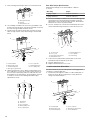
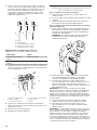
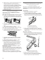
4. Use a Phillips screwdriver to connect the green ground wire
from the power supply cord to the range with the ground-
link screw and ground-link section. The ground wire must be
attached first.
5. Use 3/8" (9.5 mm) nut driver to connect the neutral (white)
wire to the center terminal block post with one of the 10–32
hex nuts.
A. 10–32 hex nut
B. Ground-link screw
C. Line 2 (red)
D. Green ground wire
E. Neutral (center) wire
F. Line 1 (black)
6. Connect line 2 (red) and line 1 (black) wires to the outer
terminal block posts with 10-32 hex nuts.
7. Securely tighten hex nuts.
NOTE: For power supply cord replacement, use only a
power cord rated at 250 volts minimum, 40 amps or 50 amps
that is marked for use with nominal 1³⁄8" (3.5 cm) diameter
connection opening, with ring terminals and marked for use
with ranges.
8. Tighten strain relief screws.
9. Replace terminal block access cover.
3-wire connection: Power Supply Cord
Use this method only if local codes permit connecting chassis
ground conductor to neutral wire of power supply cord.
1. Feed the power supply cord through the strain relief on the
cord/conduit plate on bottom of range. Allow enough slack
to easily attach the wiring to the terminal block.
A. Terminal block
B. Ground-link screw
C. UL listed strain relief
D. Power supply cord wires - large opening
2. Use 3/8" (9.5 mm) nut driver to connect the neutral (white)
wire to the center terminal block post with one of the 10–32
hex nuts.
A. 10–32 hex nut
B. Line 2 (red)
C. Ground-link screw
D. Neutral (white) wire
E. Line 1 (black)
3. Connect line 2 (red) and line 1 (black) wires to the outer
terminal block posts with 10-32 hex nuts.
4. Securely tighten hex nuts.
NOTE: For power supply cord replacement, use only a
power cord rated at 250 volts minimum, 40 amps or 50 amps
that is marked for use with nominal 1³⁄8" (3.5 cm) diameter
connection opening, with ring terminals and marked for use
with ranges.
5. Tighten strain relief screws.
6. Replace terminal block access cover.
Direct Wire Installation: Copper or Aluminum Wire
This range may be connected directly to the fuse disconnect or
circuit breaker box. Depending on your electrical supply, make
the required 3-wire or 4-wire connection.
1. Strip outer covering back 3" (7.6 cm) to expose wires. Strip
the insulation back 3/8" (9.5 mm) from the end of each wire.
2. Allow enough slack in the wire to easily attach the wiring
terminal block.
3. Complete electrical connection according to your type of
electrical supply (4-wire or 3-wire connection).
4-wire Connection: Direct Wire
Use this method for:
■New branch-circuit installations (1996 NEC)
■Mobile homes
■Recreational vehicles
■In an area where local codes prohibit grounding through the
neutral
A
B
C
D
E
A
B
C
F
D
E
A
B
D
C
3"
(7.6 cm)
3/8"
(1.0 cm)

12
1. Part of metal ground strap must be cut out and removed.
A. Metal ground strap
B. Discard
C. Ground-link screw
2. Use a Phillips screwdriver to remove the ground-link screw
from the back of the range. Save the ground-link screw and
the end of the ground link under the screw.
3. Pull the wires through the strain relief on bottom of range.
Allow enough slack to easily attach wiring to the terminal
block.
A. Terminal block
B. Ground-link screw
C. Cord/conduit plate
D. Bare (green) ground wire
E. Line 2 (red) wire
F. Neutral (white) wire
G. Line 1 (black) wire
4. Attach terminal lugs to line 1 (black), neutral (white), and
line 2 (red) wires. Loosen (do not remove) the setscrew on
the front of the terminal lug and insert exposed wire end
through bottom of terminal lugs. Securely tighten setscrew
to torque as shown in the following Bare Wire Torque
Specifications chart.
A. Terminal lug
B. Setscrew
C. Line 2 (red) wire
D. Neutral (white) wire
E. Line 1 (black) wire
Bare Wire Torque Specifications
Attaching terminal lugs to the terminal block - 20 lbs-in.
(2.3 N-m)
Wire Awg Torque
8 gauge copper 25 lbs-in. (2.8 N-m)
6 gauge aluminum 35 lbs-in. (4.0 N-m)
5. Use a hex or Phillips screwdriver to connect the bare (green)
ground wire to the range with the ground-link screw and
ground-link section. The ground wire must be attached first
and must not contact any other terminal.
6. Use 3/8" nut driver to connect the neutral (white) wire to the
center terminal block post with one of the 10–32 hex nuts.
A. 10–32 hex nut
B. Line 2 (red)
C. Bare (green) ground wire
D. Ground-link screw
E. Neutral (white) wire
F. Line 1 (black)
G. Terminal lug
7. Connect line 2 (red) and line 1 (black) wires to the outer
terminal block posts with 10-32 hex nuts.
8. Securely tighten hex nuts.
9. Replace terminal block access cover.
3-wire connection: Direct Wire
Use this method only if local codes permit connecting ground
conductor to neutral supply wire.
1. Pull the wires through the conduit on cord/conduit plate on
bottom of range. Allow enough slack to easily attach the
wiring to the terminal block.
A. Terminal block
B. Ground-link screw
C. Cord/conduit plate
D. Line 2 (red) wire
E. Bare (green) ground wire
F. Line 1 (black) wire
A
B
C
A
B
C
D
E
G
F
A
B
CDE
B
A
G
E
C
D
F
A
B
C
DE
F

13
2. Attach terminal lugs to line 2 (red), bare (green) ground, and
line 1 (black) wires. Loosen (do not remove) the setscrew
on the front of the terminal lug and insert exposed wire end
through bottom of terminal lugs. Securely tighten setscrew
to torque as shown in the following Bare Wire Torque
Specifications chart.
A. Terminal lug
B. Setscrew
C. Line 2 (red) wire
D. Bare (green) ground wire
E. Line 1 (black) wire
Bare Wire Torque Specifications
Attaching terminal lugs to the terminal block - 20 lbs-in.
(2.3 N-m)
Wire Awg Torque
8-gauge copper 25 lbs-in. (2.8 N-m)
6-gauge aluminum 35 lbs-in. (4.0 N-m)
3. Use 3/8" nut driver to connect the bare (green) ground wire
to the center terminal block post with one of the 10–32 hex
nuts.
A. 10–32 hex nut
B. Line 2 (red)
C. Ground-link screw
D. Bare (green) ground wire
E. Line 1 (black)
F. Terminal lug
4. Connect line 2 (red) and line 1 (black) wires to the outer
terminal block posts with 10-32 hex nuts.
5. Securely tighten hex nuts.
6. Replace terminal block access cover.
Verify Anti-Tip Bracket Is Installed
and Engaged
On Ranges Equipped with a Storage Drawer:
1. Remove the storage drawer. See the “Storage Drawer”
section.
2. Use a flashlight to look underneath the bottom of the range.
3. Visually check that the rear range foot is inserted into the slot
of the anti-tip bracket.
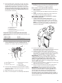
On Ranges Equipped with a Warming Drawer or Premium
Storage Drawer:
1. Place the outside of your foot against the bottom front of the
warming drawer or premium storage drawer, and grasp the
lower right or left side of the control panel as shown.
NOTE: If your countertop is mounted with a backsplash, it
may be necessary to grasp the range higher than is shown in
the illustration.
2. Slowly attempt to tilt the range forward.
If you encounter immediate resistance, the range foot is
engaged in the anti-tip bracket.
3. If the rear of the range lifts more than 1/2" (12.7 mm) off the
floor without resistance, stop tilting the range and lower it
gently back to the floor. The range foot is not engaged in the
anti-tip bracket.
IMPORTANT: If there is a snapping or popping sound when
lifting the range, the range may not be fully engaged in the
bracket. Check to see if there are obstructions keeping the range
from sliding to the wall or keeping the range foot from sliding
into the bracket. Verify that the bracket is held securely in place
by the mounting screws.
4. Slide the range forward, and verify that the anti-tip bracket is
securely attached to the floor or wall.
5. Slide range back so the rear range foot is inserted into the
slot of the anti-tip bracket.
IMPORTANT: If the back of the range is more than 2" (5.1 cm)
from the mounting wall, the rear range foot may not engage the
bracket. Slide the range forward and determine if there is an
obstruction between the range and the mounting wall. If you
need assistance or service, refer to the “Assistance or Service”
section of the Use and Care Guide, or the “Warranty” section of
the User Instructions, for contact information.
A
B
CDE
B
F
A
E
D
C

14
6. Repeat steps 1 and 2 to ensure that the range foot is
engaged in the anti-tip bracket.
If the rear of the range lifts more than 1/2" (12.7 mm) off
the floor without resistance, the anti-tip bracket may not be
installed correctly. Do not operate the range without anti-
tip bracket installed and engaged. Please reference the
“Assistance or Service” section of the Use and Care Guide,
or the “Warranty” section of the User Instructions, to contact
service.
Level Range
Determine if you have AquaLift® Technology or Steam Clean by
referring to the “Range Care” section of the User Instructions.
For Ranges with AquaLift® Technology or Steam Clean:
1. Place level on the oven bottom as indicated in one of the two
figures below depending on the size of the level. Check with
the level: side to side and front to back.
2. If range is not level, pull range forward until rear leveling leg
is removed from the anti-tip bracket.
3. Follow the directions in Style 1 or Style 2, depending on the
style of drawer supplied with the range.
For Ranges without AquaLift® Technology or Steam Clean:
1. Place a standard flat rack in the oven.
2. Place level on the rack and check levelness of the range, first
side to side; then front to back.
3. If range is not level, pull range forward until rear leveling leg
is removed from the anti-tip bracket.
4. Follow the directions in Style 1 or Style 2, depending on the
style of drawer supplied with the range.
Style 1: Ranges Equipped with a Storage Drawer:
Use a 1/4" (6.4 mm) drive ratchet, wrench or pliers to adjust
leveling legs up or down until the range is level. Push range
back into position. Check that rear leveling leg is engaged in
the anti-tip bracket.
Style 2: Ranges Equipped with a Warming Drawer or
Premium Storage Drawer:
Use a wrench or pliers to adjust leveling legs up or down until
the range is level. Push range back into position. Check that rear
leveling leg is engaged in the anti-tip bracket.
NOTE: Range must be level for satisfactory baking performance
and best cleaning results using AquaLift® Technology and Steam
Clean functions.
Warming Drawer or Premium Storage
Drawer
(on some models)
Remove all items from inside the warming drawer or premium
storage drawer, and allow the range to cool completely before
attempting to remove the drawer.
To Remove:
1. Open the warming drawer or premium storage drawer to its
fully open position.
2. Using a flat-blade screwdriver, gently loosen the warming
drawer or premium storage drawer from the glide alignment
notch and lift up the drawer alignment tab from the glide.
A. Flat-blade screwdriver
B. Drawer alignment tab
C. Drawer glide notch
3. Repeat Step 2 on the other side. The warming drawer or
premium storage drawer is no longer attached to the drawer
glides. Using both hands, pick up the warming drawer or
premium storage drawer to complete the removal.
To Replace:
1. Align the forward drawer notches with the notches in the
drawer glides on both sides. Place the rear alignment tabs
into the drawer glides on both sides.
A. Drawer alignment tab
B. Drawer glide notch
2. Push the warming drawer or premium storage drawer in all
the way.
3. Gently open and close the warming drawer or premium
storage drawer to ensure it is seated properly on the glides
on both sides.
A
B
C
A
B

15
Storage Drawer
(on some models)
The storage drawer can be removed. Before removing, make
sure drawer is cool and empty.
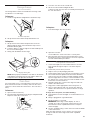
To Remove:
1. Pull the storage drawer straight back to the drawer stop.
A. Drawer stop notch
2. Lift up the front of the drawer and pull the drawer out.
To Replace:
1. Lift up the front of the drawer and place the rear of the
drawer inside the range so that the drawer stop notch is
behind the drawer glide.
2. Lower the drawer so that the edge of the slide rail drops into
the slot in the drawer glide.
3. Slowly push the drawer into the range.
A. Engage drawer glide.
NOTE: When properly installed, the rear slides on the bottom
of the drawer will engage the base rails and the drawer will
not tip when items are placed in the drawer.
Oven Door
For normal range use, it is not suggested to remove the oven
door. However, if removal is necessary, make sure the oven is
off and cool. Then, follow these instructions. The oven door is
heavy.
To Remove:
1. Open oven door all the way.
2. Pinch the hinge latch between two fingers and pull forward.
Repeat on other side of oven door.
A. Hinge latch
3. Close the oven door as far as it will shut.
4. Lift the oven door while holding both sides.
Continue to push the oven door closed and pull it away from
the oven door frame.
To Replace:
1. Insert both hanger arms into the door.
2. Open the oven door.
You should hear a “click” as the door is set into place.
3. Move the hinge levers back to the locked position. Check
that the door is free to open and close. If it is not, repeat the
removal and installation procedures.
Complete Installation
1. Check that all parts are now installed. If there is an extra
part, go back through the steps to see which step was
skipped.
2. Check that you have all of your tools.
3. Dispose of/recycle all packaging materials.
4. Check that the range is level. See the “Level Range” section.
5. Use a mild solution of liquid household cleaner and warm
water to remove waxy residue caused by shipping material.
Dry thoroughly with a soft cloth. For more information, read
the “Range Care” section of the Use and Care Guide or User
Instructions or User Instructions.
6. Read the “Range Use” section in the range Use and Care
Guide or User Instructions.
7. Plug power cord into appropriate outlet. Turn power on.
8. Turn on surface burners and oven. See the Use and Care
Guide or User Instructions for specific instruction on range
operation.
If range does not operate, check the following:
■Household fuse is intact and tight; or circuit breaker has not
tripped.
■Range is plugged into a grounded outlet.
■Electrical supply is connected.
IMPORTANT: If the range control displays an “F9” or
“F9, E0” error code, the electrical outlet in the home may
be miswired. Contact a qualified electrician to verify the
electrical supply.
■See the “Troubleshooting” section in the Use and Care Guide
or User Instructions.
When the range has been on for 5 minutes, check for heat.
If range is cold, turn off the range and contact a qualified
technician.
A
A
A

16
Moving the Range
When moving range, slide range onto cardboard or hardboard to
avoid damaging the floor covering.
If removing the range is necessary for cleaning or maintenance:
For power supply cord-connected ranges:
1. Slide range forward.
2. Unplug the power supply cord.
3. Complete cleaning or maintenance.
4. Plug in power supply cord.
5. Check that the anti-tip bracket is installed and engaged.
See the “Verify Anti-Tip Bracket Is Installed and Engaged”
section.
6. Check that range is level.
For direct-wired ranges:
1. Disconnect power.
2. Slide range forward.
3. Complete cleaning or maintenance.
4. Check that the anti-tip bracket is installed and engaged.
See the “Verify Anti-Tip Bracket Is Installed and Engaged”
section.
5. Check that range is level.
6. Reconnect power.
WARNING
Tip Over Hazard
A child or adult can tip the range and be killed.
Install anti-tip bracket to floor or wall per installation
instructions.
Slide range back so rear range foot is engaged in the
slot of the anti-tip bracket.
Re-engage anti-tip bracket if range is moved.
Do not operate range without anti-tip bracket installed
and engaged.
Failure to follow these instructions can result in death
or serious burns to children and adults.
WARNING
Electrical Shock Hazard
Disconnect power before servicing.
Replace all parts and panels before operating.
Failure to do so can result in death or electrical shock.

17
SÉCURITÉ DE LA CUISINIÈRE
Risque possible de décès ou de blessure grave si
Risque possible de décès ou de blessure grave
si vous ne suivez pas les instructions.
Tous les messages de sécurité vous diront quel est le danger potentiel et vous disent comment réduire le risque de
Votre sécurité et celle des autres est très importante.
Nous donnons de nombreux messages de sécurité importants dans ce manuel et sur votre appareil ménager.
Ce symbole d’alerte de sécurité vous signale les dangers potentiels de décès et de blessures graves
Tous les messages de sécurité suivront le symbole d’alerte de sécurité et le mot “DANGER” ou
“AVERTISSEMENT”. Ces mots signifient :
DANGER
AVERTISSEMENT
Assurez-vous de toujours lire tous les messages de sécurité et de vous y conformer.
à vous et à d’autres.
Voici le symbole d’alerte de sécurité.
vous ne suivez pas immédiatement les instructions.
blessure et ce qui peut se produire en cas de non-respect des instructions.
Risque de basculement
Un enfant ou une personne adulte peut faire basculer la cuisinière, ce qui peut causer un
décès.
Fixer la bride antibasculement au plancher ou au mur, conformément aux instructions
d'installation.
Faire glisser de nouveau la cuisinière de façon à ce que le pied arrière de la cuisinière se
trouve dans la fente de la bride antibasculement.
Réengager la bride antibasculement si la cuisinière a été déplacée.
Ne pas faire fonctionner la cuisinière si la bride antibasculement n'est pas installée et engagée.
Le non-respect de ces instructions peut causer un décès ou des brûlures graves aux enfants et
aux adultes.
Bride
antibasculement
Pour vérifier que la bride antibasculement est bien installée et engagée :
•Faire glisser la cuisinière vers l'avant.
•Vérifier que la bride antibasculement est bien fixée au plancher ou au mur.
•Faire de nouveau glisser la cuisinière vers l'arrière de sorte que le pied de la cuisinière
se trouve sous la bride antibasculement.
•Voir les instructions d'installation pour plus de détails.
Pied de
la cuisinière
AVERTISSEMENT

18
EXIGENCES D’INSTALLATION
Outils et pièces
Rassembler les outils et pièces nécessaires avant d’entreprendre
l’installation. Lire et observer les instructions fournies avec
chacun des outils de la liste ci-dessous.
Outils nécessaires
■Ruban à mesurer
■Tournevis à lame plate
■Tournevis cruciforme
■Niveau
■Marteau
■Perceuse manuelle ou
électrique
■Clé ou pince
■Marqueur ou crayon
Pièces fournies
Vérifier que toutes les pièces sont présentes.
■3 écrous hexagonaux de 10-32 (fixés au bornier)
■3 attaches de bornes
A. Bride antibasculement
B. Vis 12 x 15⁄8" (41 mm) (2 vis)
■La bride antibasculement doit être bien fixée au plancher ou
au mur. La profondeur du plancher peut nécessiter des vis
plus longues pour l’ancrage de la bride dans le plancher.
Pièces nécessaires
En cas d’utilisation d’un cordon d’alimentation électrique :
■Cordon d’alimentation (homologation UL) conçu pour
l’utilisation avec une cuisinière. Pour service 250 V minimum,
40 A ou 50 A, compatible avec une ouverture de diamètre
nominal de 1³⁄8" (3,5 cm) pour le raccordement, et avec
cosses rondes ou en fourche à pointes relevées à l’extrémité
de chaque conducteur.
■Un serre-câbles (homologation UL).
Consulter les codes locaux. Vérifier l’alimentation électrique
existante. Voir la section “Spécifications électriques”
correspondante.
Il est recommandé de faire réaliser tous les raccordements
électriques par un électricien qualifié agréé.
■Ruban adhésif de masquage
■Clé à cliquet de 1/4"
(6,4 mm)
■Tourne-écrou de 1/4"
(6,4 mm)
■Tourne-écrou de 3/8"
(9,5 mm) et 5/16" (8 mm)
■Foret de 1/8" (3,2 mm)
(pour planchers en bois)
■Cisaille de ferblantier ou
coupe-fils de gros diamètre
(pour couper la tresse
de mise à la terre le cas
échéant)
Exigences d’emplacement
IMPORTANT : Observer les dispositions de tous les codes et
règlements en vigueur.
■C’est à l’installateur qu’incombe la responsabilité de
respecter les distances de séparation spécifiées sur la
plaque signalétique. La plaque signalétique est située sur le
châssis derrière un coin supérieur de la porte ou d’un côté
du tiroir.
■Afin de supprimer le risque de brûlures ou d’incendie en
se penchant au-dessus des unités de surface chauffées,
le rangement en armoire au-dessus des unités de surface
doit être évité. Si des placards de rangement sont prévus,
le risque peut être réduit par l’installation d’une hotte de
cuisinière ou d’un ensemble hotte/micro-ondes dépassant
horizontalement de 5" (12,7 cm) au moins par rapport au bas
des placards.
■Respecter les dimensions indiquées pour les ouvertures à
découper dans les meubles. Ces dimensions constituent les
valeurs minimales des dégagements.
■La bride antibasculement doit être installée. Pour
l’installation de la bride antibasculement fournie avec
la cuisinière, voir la section “Installation de la bride
antibasculement”.
■Une source d’électricité avec liaison à la terre est nécessaire.
Voir la section “Spécifications électriques” correspondante.
IMPORTANT : Pour éviter d’endommager les placards, consulter
le constructeur de la maison ou le fabricant des placards pour
déterminer si les matériaux utilisés peuvent subir un changement
de couleur, une déstratification ou d’autres dommages. Ce four a
été conçu conformément aux exigences des normes UL et CSA
International et respecte les températures maximales permises
de 194 °F (90 °C) pour les placards en bois.
Résidence mobile – Spécifications additionnelles à
respecter lors de l’installation
L’installation de cette cuisinière doit être conforme aux
dispositions de la norme Manufactured Home Construction and
Safety Standard, Title 24 CFR, Part 3280 (anciennement Federal
Standard for Mobile Home Construction and Safety, Title 24,
HUD Part 280). Lorsque cette norme n’est pas applicable,
utiliser la norme Standard for Manufactured Home Installations,
ANSI A225.1/NFPA 501A ou respecter les dispositions des
codes locaux.
Autres critères à respecter pour une installation dans une
résidence mobile :
■Lorsque cette cuisinière est installée dans une résidence
mobile, elle doit être fixée selon les instructions contenues
dans le présent document.
■Pour une installation dans une résidence mobile, un câble ou
cordon d’alimentation à quatre conducteurs doit être utilisé.
Le câblage de l’appareil devra être révisé. Voir la section
“Raccordement électrique – É.-U. seulement”.
A
B

19
Dimensions du produit
REMARQUE : L’apparence du modèle peut être différente de l’image.
IMPORTANT : La cuisinière doit être d’aplomb après l’installation. Suivre les instructions de la section “Réglage de l’aplomb de la
cuisinière”. Il n’est pas recommandé d’utiliser la table de cuisson comme référence pour établir l’aplomb de la cuisinière.
*La cuisinière peut être surélevée d’environ 1" (2,5 cm) en ajustant les pieds de nivellement.
**L’avant de la porte et du tiroir peuvent s’avancer davantage en fonction du style du produit.
A
B
C
D
F
E
A. Profondeur maximale avec la poignée : 27 3/8" (69,5 cm)
B. Hauteur (max) avec les pieds de nivellement complètement relevés : 46 1/2" (118,1 cm)*
C. Hauteur (max) de la table de cuisson avec les pieds de nivellement complètement relevés :
36" (91,4 cm)*
D. Largeur : 29 7⁄8" (75,9 cm)
E. Profondeur de l’arrière de la cuisinière à l’avant de la table de cuisson : 25 5⁄16" (64,3 cm).**
F. Plaque signalétique (située sur le cadre derrière un coin supérieur de la porte ou de chaque
côté du tiroir)

20
Dimensions du placard
Les dimensions de l’espace entre les placards correspondent
à une installation entre des placards de 24" (61,0 cm) de
profondeur, avec plan de travail de 25" (64,0 cm) de profondeur
et de 36" (91,4 cm) de hauteur.
IMPORTANT : En cas d’installation d’une hotte ou d’un
ensemble hotte/micro-ondes au-dessus de la cuisinière, suivre
les instructions fournies avec la hotte ou l’ensemble hotte/micro-
ondes concernant les dimensions de dégagement à respecter
au-dessus de la surface de la table de cuisson.
Une cuisinière autoportante peut être installée sans aucun
dégagement à proximité de parois combustibles.
A. Profondeur max. du placard supérieur : 13" (33,0 cm).
B. Largeur min. de l’ouverture : 30" (76,2 cm)
C. Pour le dégagement minimum vers la partie supérieur e de
la table de cuisson, voir la REMARQUE*
D. Largeur min. de l’ouverture : 30
" (76,2 cm)
E. Prise : 8" (20,3 cm) à 22" (55,9 cm) de l’un des deux
placards, 5 ¹⁄2" (14,0 cm) max. du plancher
F. La porte ou charnièr e du placard ne doit pas dépasser à
l’intérieur de l’ouverture
* REMARQUE : Distance de séparation de 24" (61,0 cm) ou
plus lorsque le fond d’un placard de bois ou de métal est
recouvert d’une planche ignifugée d’au moins 1/4" (0,64 cm)
recouverte d’une feuille métallique d’épaisseur égale ou
supérieure à : acier calibre 28 MSG, acier inoxydable 0,015"
(0,4 mm), aluminium 0,024" (0,6 mm) ou cuivre 0,020"
(0,5 mm).
Distance de séparation minimale de 30" (76,2 cm) ou plus
entre le dessus de la table de cuisson et le fond d’un placard
de bois ou de métal non protégé.
Spécifications électriques – É.-U. seulement
Si l’on utilise un conducteur distinct de liaison à la terre
lorsque les codes le permettent, il est recommandé qu’un
électricien qualifié vérifie que la liaison à la terre et le calibre des
conducteurs sont conformes aux codes locaux.
Ne pas utiliser de rallonge.
S’assurer que le raccordement électrique est adéquat et
conforme au code national de l’électricité, ANSI/NFPA 70 –
dernière édition, et à tous les codes et règlements locaux en
vigueur.
Pour obtenir un exemplaire des normes des codes ci-dessus,
contacter :
National Fire Protection Association
1 Batterymarch Park
Quincy, MA 02169-7471
AVERTISSEMENT : Un raccordement inapproprié du
conducteur de mise à la terre de l’équipement peut causer
un risque de choc électrique. Vérifier avec un électricien ou
un technicien de dépannage qualifié en cas de doute quant à
la qualité de la liaison à la terre de l’appareil. Ne pas modifier
la prise du cordon d’alimentation. Si elle ne correspond pas
à la prise de sortie, faire installer une fiche appropriée par un
électricien qualifié.
Raccordement électrique
Pour installer la cuisinière de façon appropriée, il faut établir
le type de raccords électriques que l’on utilisera et suivre les
instructions de ce document.
■La cuisinière doit être alimentée par une source d’électricité
et une tension appropriées, comme spécifiée sur la plaque
signalétique. La plaque signalétique est située sur le châssis
derrière un coin supérieur de la porte ou d’un côté du tiroir.
Consulter les images du point “Dimensions du produit” de la
section “Exigences d’emplacement”.
■La borne du neutre de cette cuisinière est raccordée à la
caisse. Utiliser un cordon d’alimentation électrique (raccord
flexible) à 3 fils homologué UL, pour 40 ou 50 A (consulter
le tableau de la puissance nominale de la cuisinière). Si les
codes locaux interdisent le raccordement de la terre au
neutre, utiliser un cordon d’alimentation électrique à 4 fils
de 250 V, 40 ou 50 A en nominal et dont l’utilisation avec les
cuisinières a été testée.
Puissance
nominale de
la cuisinière*
Intensité nominale spécifiée
du cordon d’alimentation et
de la protection du circuit
120/240 V 120/208 V A
8,8 à 16,5 kW 7,8 à 12,5 kW 40 ou 50**
16,6 à
22,5 kW 12,6 à
18,5 kW 50
* La charge NEC calculée est inférieure à la charge totale
connectée indiquée sur la plaque signalétique.
** En cas de raccordement à un circuit de 50 A, utiliser un cordon
de 50 A nominaux avec son ensemble. Pour les ensembles
avec cordon de 50 A nominaux, utiliser des ensembles conçus
pour être utilisés avec une ouverture de raccord d’un diamètre
nominal de 1 ³⁄8" (34,9 cm).
■L’emploi d’un disjoncteur est recommandé.
■La cuisinière peut être raccordée directement au disjoncteur
(ou coupe-circuit avec fusible) par l’intermédiaire de
câble à conducteurs de cuivre ou aluminium, à blindage
métallique flexible ou à gaine non métallique. Voir la section
“Raccordement électrique – É.-U. seulement”.
■Prévoir 2 à 3 pi (61,0 cm à 91,4 cm) de mou pour le câble
afin de pouvoir déplacer la cuisinière en cas de réparation.
A
B
D
F
E
C
La page est en cours de chargement...
La page est en cours de chargement...
La page est en cours de chargement...
La page est en cours de chargement...
La page est en cours de chargement...
La page est en cours de chargement...
La page est en cours de chargement...
La page est en cours de chargement...
La page est en cours de chargement...
La page est en cours de chargement...
La page est en cours de chargement...
La page est en cours de chargement...
La page est en cours de chargement...
La page est en cours de chargement...
La page est en cours de chargement...
La page est en cours de chargement...
La page est en cours de chargement...
La page est en cours de chargement...
La page est en cours de chargement...
La page est en cours de chargement...
La page est en cours de chargement...
La page est en cours de chargement...
La page est en cours de chargement...
La page est en cours de chargement...
La page est en cours de chargement...
La page est en cours de chargement...
La page est en cours de chargement...
La page est en cours de chargement...
-
 1
1
-
 2
2
-
 3
3
-
 4
4
-
 5
5
-
 6
6
-
 7
7
-
 8
8
-
 9
9
-
 10
10
-
 11
11
-
 12
12
-
 13
13
-
 14
14
-
 15
15
-
 16
16
-
 17
17
-
 18
18
-
 19
19
-
 20
20
-
 21
21
-
 22
22
-
 23
23
-
 24
24
-
 25
25
-
 26
26
-
 27
27
-
 28
28
-
 29
29
-
 30
30
-
 31
31
-
 32
32
-
 33
33
-
 34
34
-
 35
35
-
 36
36
-
 37
37
-
 38
38
-
 39
39
-
 40
40
-
 41
41
-
 42
42
-
 43
43
-
 44
44
-
 45
45
-
 46
46
-
 47
47
-
 48
48


dans d''autres langues
- English: Whirlpool WFE975H0HV User manual
- español: Whirlpool WFE975H0HV Manual de usuario
- português: Whirlpool WFE975H0HV Manual do usuário