
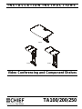
INSTALLATION INSTRUCTIONS
Instrucciones de instalación
Installationsanleitung
Instruções de Instalação
Istruzioni di installazione
Installatie-instructies
Instructions d´installation
TA100
TA200 TA250
Video Conferencing and Component Shelves
Spanish Product Description
German Product Description
Portuguese Product Description
Italian Product Description
Dutch Product Description
French Product Description
TA100/200/250

TA100/200/250 Installation Instructions
2
DISCLAIMER
Milestone AV Technologies and its affiliated corporations and
subsidiaries (collectively "Milestone"), intend to make this
manual accurate and complete. However, Milestone makes no
claim that the information contained herein covers all details,
conditions or variations, nor does it provide for every possible
contingency in connection with the installation or use of this
product. The information contained in this document is subject
to change without notice or obligation of any kind. Milestone
makes no representation of warranty, expressed or implied,
regarding the information contained herein. Milestone assumes
no responsibility for accuracy, completeness or sufficiency of
the information contained in this document.
Chief® is a registered trademark of Milestone AV Technologies.
All rights reserved.
IMPORTANT SAFETY INSTRUCTIONS!
WARNING: A WARNING alerts you to the possibility of
serious injury or death if you do not follow the instructions.
CAUTION: A CAUTION alerts you to the possibility of
damage or destruction of equipment if you do not follow the
corresponding instructions.
WARNING: Failure to read, thoroughly understand, and
follow all instructions can result in serious personal injury,
damage to equipment, or voiding of factory warranty! It is the
installer’s responsibility to make sure all components are
properly assembled and installed using the instructions
provided.
WARNING: Failure to provide adequate structural strength
for this component can result in serious personal injury or
damage to equipment! It is the installer’s responsibility to
make sure the structure to which this component is attached
can support five times the combined weight of all equipment.
Reinforce the structure as required before installing the
component.
WARNING: Exceeding the weight capacity can result in
serious personal injury or damage to equipment! It is the
installer’s responsibility to make sure the combined weight of
all equipment and accessories mounted on each TA100/200/
250 shelf does not exceed 10 lbs (4.54 kg) per shelf.
WARNING: RISK OF INJURY TO PERSONS! Do not use
this mounting system to support video equipment such as
televisions or computer monitors.
WARNING: Do not use this product outdoors.
--SAVE THESE INSTRUCTIONS--
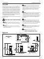
DIMENSIONS
17.25
DISTANCE TO C/L
OF TS3XXX SERIES
SWING ARMS
438
17.56
HIGHEST POSITION
WITH EXTENDER BRACKET
18.00
457.2
5.90
149.7
1.25
31.8
12.00
304.8
11.19
284.2
21.75
DISTANCE TO C/L
OF TS3XXX SERIES
SWING ARMS
552.3
22.06
DISTANCE TO C/L
OF TS5XXX SERIES
LOWEST POSITION
4.50
HEIGHT
ADHUSTMENT
114.3 15.00
SHELF CAN BE USED
EITHER ABOVE OR BELOW
TA100

Installation Instructions TA100/200/250
3
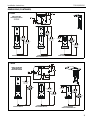
DIMENSIONS (CONTINUED)
22.16
DISTANCE TO C/L OF
TS5XXX SERIES
SWING ARMS
562.9
21.85
DISTANCE TO C/L OF
THE TS3XXX SERIES
HIGHEST EXTENSION
22.16
DISTANCE TO C/L OF
TS5XXX SERIES
SWING ARMS
562.9
21.85
DISTANCE TO C/L OF
THE TS3XXX SERIES
LOWEST EXTENSION
WITH EXTENDER BRACKET
4.50
HEIGHT
ADJUSTMENT
114.3
15.41
DISTANCE TO C/L OF
TS5XXX SERIES
HIGHEST EXTENSION
WITHOUT EXTENDER BRACKET
8.00
203.2
4.00
101.6
.28
7.1
4.00
101.6
1.25
31.8
.25
6.4
7.25
184.2
SHELF CAN BE USED
EITHER ABOVE OR BELOW
TA200
21.85
DISTANCE TO C/L OF
TS3XXX SERIES
SWING ARMS
555
22.16
HIGHEST EXTENSION
17.66
DISTANCE TO C/L OF
TS5XXX SERIES
SWING ARMS
448.6
17.35
DISTANCE TO C/L OF
TS3XXX SERIES
LOWEST EXTENSION
WITH EXTENDER BRACKET
4.50
HEIGHT
ADJUSTMENT
114.3
15.10
DISTANCE TO C/L OF
TS3XXX SERIES
HIGHEST EXTENSION
WITHOUT EXTENDER BRACKET
12.00
304.8
6.00
152.4
1.90
48.1
4.00
101.6
.28
7.1
1.25
31.8 .25
6.4
3.65
92.6
7.25
184.2
SHELF CAN BE USED
EITHER ABOVE OR
BELOW THE SCREEN
TA250

TA100/200/250 Installation Instructions
4
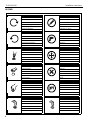
LEGEND
Tighten Fastener
Apretar elemento de fijación
Befestigungsteil festziehen
Apertar fixador
Serrare il fissaggio
Bevestiging vastdraaien
Serrez les fixations
Loosen Fastener
Aflojar elemento de fijación
Befestigungsteil lösen
Desapertar fixador
Allentare il fissaggio
Bevestiging losdraaien
Desserrez les fixations
Phillips Screwdriver
Destornillador Phillips
Kreuzschlitzschraubendreher
Chave de fendas Phillips
Cacciavite a stella
Kruiskopschroevendraaier
Tournevis à pointe cruciforme
Open-Ended Wrench
Llave de boca
Gabelschlüssel
Chave de bocas
Chiave a punte aperte
Steeksleutel
Clé à fourche
By Hand
A mano
Von Hand
Com a mão
A mano
Met de hand
À la main
Hex-Head Wrench
Llave de cabeza hexagonal
Sechskantschlüssel
Chave de cabeça sextavada
Chiave esagonale
Zeskantsleutel
Clé à tête hexagonale
Pencil Mark
Marcar con lápiz
Stiftmarkierung
Marcar com lápis
Segno a matita
Potloodmerkteken
Marquage au crayon
Drill Hole
Perforar
Bohrloch
Fazer furo
Praticare un foro
Gat boren
Percez un trou
Adjust
Ajustar
Einstellen
Ajustar
Regolare
Afstellen
Ajuster
Remove
Quitar
Entfernen
Remover
Rimuovere
Verwijderen
Retirez
Optional
Opcional
Optional
Opcional
Opzionale
Optie
En option
Security Wrench
Llave de seguridad
Sicherheitsschlüssel
Chave de segurança
Chiave di sicurezza
Veiligheidssleutel
Clé de sécurité

TA100/200/250 Installation Instructions
5
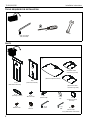
TOOLS REQUIRED FOR INSTALLATION
PARTS
5/32" (included)
1/8" (included)
#2
3/8"
A (1) B (1)
C (1)
[attachment bracket]
[extension bracket]
[TA100 component shelf]
[TA200 8" video
conferencing shelf]
[TA250 12" video
conferencing shelf]
D (1)
[backing bracket] E (4)
#10-24 x 3/8" F (6)
1/4-20 x 5/8" G (6)
1/4"
H (4) 5/32"
J (4) 1/8"
K (1) L (1)
#10-24 x 1/2" #10-24
M (8)
1" adhesive hook
and loop
N (1)*
1/4-20 x 3/8"
*only with TA200 and TA250

TA100/200/250 Installation Instructions
6
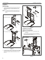
Installation
Shelf Assembly
1. Use three 1/4-20 x 5/8" button head cap screws (F) and
three 1/4" washers (G) to connect shelf (C) to either
extension bracket (B) or attachment bracket (A). (See
Figure 1)
NOTE: Use extension bracket (B) for larger displays or if
component needs to be mounted further from the
display.
Figure 1
2. If using extension bracket, use three 1/4-20 x 5/8" button
head cap screws (F) and three 1/4" washers (G) to attach
extension bracket (B) to attachment bracket (A). (See
Figure 2)
Figure 2
Installation to Faceplate
TS525 or iCF50 Installation
NOTE: Display does NOT have to be removed for shelf
installation.
1. Use four #10-24 x 3/8" button head cap screws (E) to
connect attachment bracket (A) to swing arm faceplate.
(See Figure 3) and (See Figure 4)
Figure 3
1
(F) x 3
(G) x 3
(B)
(C)
(TA200 shown)
1
(F) x 3
(G) x 3
(A)
(C)
With extension bracket
Without extension bracket
2
(F) x 3
(G) x 3
(A)
(D)
(B)
(TA200 shown)
(display not shown for clarity)
(upper installation)
(A)
(E) x 4
1

Installation Instructions TA100/200/250
7
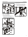
Figure 4
TS3XX or iCF30 Installation
1. If already installed, remove display from faceplate. See
swing arm installation instructions for details.
2. Use four #10-24 x 1/2" Phillips head cap screws (H) and
four #10-24 lock nuts (J) to connect attachment bracket (A)
to faceplate. (See Figure 5) and (See Figure 6)
Figure 5
Figure 6
3. Reinstall display to faceplate. See swing arm installation
instructions for details.
NOTE: If also installing side speaker brackets (TA300),
attachment bracket (A) should also be attached to
TA300 horizontal brackets for additional support. Use
hardware provided with TA300. (See Figure 7)
Figure 7
(display not shown for clarity)
(lower installation)
(E) x 4
1
(A)
(J) x 4
2
(H) x 4
(upper installation)
(display not shown
for clarity)
(lower installation)
(display not shown
for clarity)
2
(H) x 4
(J) x 4
(A)
(A)

TA100/200/250 Installation Instructions
8
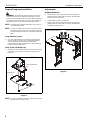
Camera/Component Installation
WARNING: Exceeding the weight capacity can result in
serious personal injury or damage to equipment! It is the
installer’s responsibility to make sure the combined weight of
all equipment and accessories mounted on the TA100/200/
250 shelves does not exceed 10 lbs (4.54 kg) per shelf.
NOTE: Mounting options will vary depending on the type of
camera being mounted.
NOTE: Camera or component can also be secured to mount
by threading cable ties or a PAC103 safety strap (not
included) through outside slots on shelf and around the
device.
Using Adhesive Squares
1. Use up to eight adhesive hook and loop squares (M) to
secure camera or component to shelf. Attach adhesive
squares to bottom of camera first and then attach
corresponding squares to shelf when the exact mounting
location has been determined.
Using Screw (TA200/250 only)
2. Install 1/4-20 x 3/8" Phillips pan machine screw (N) through
mounting slot and into hole on bottom of camera. (See
Figure 8)
Figure 8
NOTE: It is also acceptable to mount the camera directly to the
shelf without any screws or ties.
Adjustments
Height Adjustment
1. Loosen three 1/4-20 x 5/8" button head cap screws (F)
holding extension bracket (B) or shelf (C) to attachment
bracket (A). (See Figure 9)
2. Adjust height of shelf (C) as desired.
3. Tighten three 1/4-20 x 5/8" button head cap screws (F)
holding extension bracket (B) or shelf (C) to attachment
bracket (A). (See Figure 9)
Figure 9
camera (example)
2
(N)
(TA250 shown)
mounting slot
2
13
with extension bracket without extension bracket
2

Installation Instructions TA100/200/250
9

TA100/200/250 Installation Instructions
10

Installation Instructions TA100/200/250
11

TA100/200/250 Installation Instructions
USA/International A 6436 City West Parkway, Eden Prairie, MN 55344
P800.582.6480 / 952.225.6000
F877.894.6918 / 952.894.6918
Europe A Franklinstraat 14, 6003 DK Weert, Netherlands
P+31 (0) 495 580 852
F+31 (0) 495 580 845
Asia Pacific A Office No. 1 on 12/F, Shatin Galleria
18-24 Shan Mei Street
Fotan, Shatin, Hong Kong
P852 2145 4099
F852 2145 4477
Chief Manufacturing, a products division
of Milestone AV Technologies
8805-002018 Rev02
2012 Milestone AV Technologies, a
Duchossois Group Company
www.chiefmfg.com
07/12
-
 1
1
-
 2
2
-
 3
3
-
 4
4
-
 5
5
-
 6
6
-
 7
7
-
 8
8
-
 9
9
-
 10
10
-
 11
11
-
 12
12


dans d''autres langues
- English: Chief TA200 Installation guide
Documents connexes
-
Chief FCA500 Manuel utilisateur
-
-
-
-
-
-
-
-
-