
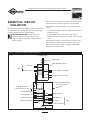
Installation &
Owner’s Manual
Guide d'Installation
et d'Utilisation
Manual de Instalación
y del Propietario
Questions? Help is just a moment away!
Preguntas? La ayuda es justa
un momento lejos!
Vous avez des questions? Vous n'avez pas
besoin d'aller loin pour trouver de l'aide!
Call: Transfer Switch Helpline
Llamada: Línea Directa de
Interruptor de Transferencia
Appelez: Ligne Directe de
Commutateur de Transfert
1-800-743-4115 M-F 8-5 CT
Web: www.briggspowerproducts.com
Models 01917-0 & 01918-0 Part No. 192636GS Rev. 2 (08/17/05)

2
Briggs & Stratton Power Products Automatic Transfer Switch
Installation and Owner’s Manual
TABLE OF CONTENTS
TABLE OF CONTENTS . . . . . . . . . . . . . . . . . . . . . . . . . . . 2
SAFETY RULES . . . . . . . . . . . . . . . . . . . . . . . . . . . . . . . . . . 3
INTRODUCTION. . . . . . . . . . . . . . . . . . . . . . . . . . . . . . . . 4
For the Home Owner: . . . . . . . . . . . . . . . . . . . . . . . . 4
For the Installing Dealer/Contractor: . . . . . . . . . . . . . 4
Owner Orientation . . . . . . . . . . . . . . . . . . . . . . . . . . . 4
Installer Responsibilities . . . . . . . . . . . . . . . . . . . . . . . . 5
Equipment Description. . . . . . . . . . . . . . . . . . . . . . . . . 5
INSTALLATION. . . . . . . . . . . . . . . . . . . . . . . . . . . . . . . . . . 5
Unpacking . . . . . . . . . . . . . . . . . . . . . . . . . . . . . . . . . . . 5
Delivery Inspection . . . . . . . . . . . . . . . . . . . . . . . . 5
Shipment Contents . . . . . . . . . . . . . . . . . . . . . . . . 5
ESSENTIAL CIRCUIT ISOLATION . . . . . . . . . . . . . . . . . . 6
Mounting Instructions . . . . . . . . . . . . . . . . . . . . . . . . . 7
Power Wiring Interconnections . . . . . . . . . . . . . . . . 7-8
SYSTEM OPERATION. . . . . . . . . . . . . . . . . . . . . . . . . . . . . 9
TESTING THE AUTOMATIC TRANSFER SWITCH . . . . 9
Automatic Sequence. . . . . . . . . . . . . . . . . . . . . . . . . . . 9
Utility Fail. . . . . . . . . . . . . . . . . . . . . . . . . . . . . . . . 9
Engine Warm-Up . . . . . . . . . . . . . . . . . . . . . . . . . . 9
Transfer . . . . . . . . . . . . . . . . . . . . . . . . . . . . . . . . . 9
Utility Pickup . . . . . . . . . . . . . . . . . . . . . . . . . . . . . 9
Retransfer . . . . . . . . . . . . . . . . . . . . . . . . . . . . . . . 9
Engine Cool Down . . . . . . . . . . . . . . . . . . . . . . . . 9
Specifications. . . . . . . . . . . . . . . . . . . . . . . . . . . . . . . . . 9
Model 01917 . . . . . . . . . . . . . . . . . . . . . . . . . . . . . 9
Model 01918 . . . . . . . . . . . . . . . . . . . . . . . . . . . . . 9
When Calling The Factory . . . . . . . . . . . . . . . . . . . . . . 9
TROUBLESHOOTING . . . . . . . . . . . . . . . . . . . . . . . . . . . 11
DIAGRAMS, EXPLODED VIEWS, PARTS LISTS . . . . . 12-15
NOTES . . . . . . . . . . . . . . . . . . . . . . . . . . . . . . . . . . 10 & 16
WARRANTY . . . . . . . . . . . . . . . . . . . . . . . . . . . . . . . . . . . 17
Copyright © 2005 Briggs & Stratton Power Products Group, LLC. All rights reserved. No part of this material may be
reproduced or transmitted in any form by any means without the express written permission of Briggs & Stratton Power
Products Group, LLC.

3
Briggs & Stratton Power Products Automatic Transfer Switch
Installation and Owner’s Manual
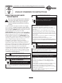
SAFETY RULES
This is the safety alert symbol. It is used to
alert you to potential personal injury
hazards. Obey all safety messages that follow
this symbol to avoid possible injury or death.
The safety alert symbol ( ) is used with a signal word
(DANGER, CAUTION,WARNING), a pictorial and/or a
safety message to alert you to hazards. DANGER indicates
a hazard which, if not avoided, will result in death or
serious injury. WARNING indicates a hazard which, if not
avoided, could result in death or serious injury.
CAUTION indicates a hazard which, if not avoided, might
result in minor or moderate injury. CAUTION, when
used without the alert symbol, indicates a situation that
could result in equipment damage. Follow safety messages
to avoid or reduce the risk of injury or death.
The manufacturer cannot possibly anticipate every possible
circumstance that might involve a hazard.The warnings in
this manual, and the tags and decals affixed to the unit are,
therefore, not all-inclusive. If you use a procedure, work
method or operating technique that the manufacturer does
not specifically recommend, you must satisfy yourself that it
is safe for you and others.You must also make sure that the
procedure, work method or operating technique that you
choose does not render the transfer switch unsafe.
SAVE THESE INSTRUCTIONS
• DO NOT touch bare wires or receptacles.
• DO NOT use transfer switch with worn, frayed, bare or
otherwise damaged wiring.
• DO NOT handle electrical cords while standing in water,
while barefoot, or while hands or feet are wet.
• If you must work around a unit while it is operating, stand on
an insulated dry surface to reduce shock hazard.
• DO NOT allow unqualified persons or children to operate or
service transfer switch.
• In case of an accident caused by electrical shock, immediately
shut down the source of electrical power and contact local
authorities. Avoid direct contact with the victim.
Failure to properly ground transfer switch can
result in electrocution.
WARNING
• Use transfer switch only for intended uses.
• If you have questions about intended use, ask dealer or
contact Briggs and Stratton Power Products.
• DO NOT expose transfer switch to excessive moisture, dust,
dirt, or corrosive vapors.
• Remain alert at all times while working on this equipment.
NEVER work on the equipment when you are physically or
mentally fatigued.
• If connected devices overheat, turn them off and turn off their
circuit breaker/fuse.
Improper treatment of transfer switch can damage it
and shorten its life.
CAUTION
• Despite the safe design of the transfer switch, operating this
equipment imprudently, neglecting its maintenance or being
careless can cause possible injury or death.
Transfer Switch contains high voltage that can
cause personal injury or death.
WARNING
• Failure to follow above warning could cause personal injury,
damage and/or malfunction of equipment.
Low voltage wire cannot be installed in same
conduit as power voltage wiring.
WARNING
Only qualified electricians should attempt installation
of this system, which must strictly comply with
applicable codes, standards and regulations.
WARNING

4
Briggs & Stratton Power Products Automatic Transfer Switch
Installation and Owner’s Manual
INTRODUCTION
Thank you for your purchase of this Briggs & Stratton
Power Products Automatic Transfer Switch.This product is
intended for use with Briggs & Stratton Home Standby
Generator sets ONLY.This is an optional home standby
system which provides an alternate source of electric
power and to serve loads such as a gas furnace,
refrigeration and communication systems that, when
stopped during any power outage, could cause discomfort,
or the like.This product DOES NOT qualify for emergency
standby as defined by NFPA 70 (NEC).
Briggs and Stratton Power Products (BSPP) has made every
effort to provide for a safe, streamlined and cost-effective
installation. Each installation is unique, it is impossible to
know of and advise of all conceivable procedures and
methods by which installation might be achieved.We do
not know all possible hazards and/or the results of each
method or procedure. For these reasons,
Only licensed electrical contractors
should install transfer switches.
Installations must strictly comply with all
applicable federal, state and local codes,
standards and regulations.
Your BSPP Transfer Switch is supplied with this combined
“Installation and Owner’s Manual”.This is an important
document and should be retained by the owner after the
installation has been completed.
Every effort has been expended to make sure that the
information in this manual is both accurate and current.
However, the manufacturer reserves the right to change,
alter or otherwise improve the system at any time without
prior notice.
For the Home Owner
To help you make informed choices and communicate
effectively with your installation contractor(s),
Read and understand the
Owner Orientation Section of this manual
BEFORE
contracting or starting
your transfer switch installation.
To arrange for proper installation, contact the store at
which you purchased your BSPP Transfer Switch, your
dealer, or your utility power provider.
The Transfer Switch Warranty is V
OID
unless the system is installed by a
licensed electrical professional.
For the Installing Dealer/Contractor
Check federal, state and local codes for questions on
installation.
If you need more information about the transfer switch,
call 1-800-743-4115, between 8:00 AM and 5:00 PM CT.
Owner Orientation
The illustrations are for typical circumstances and are
meant to familiarize you with the installation options
available with your transfer switch.
Local codes, appearance, and distances are the factors that
must be considered when negotiating with an installation
professional.As the distance from the existing electrical
service increases, compensation in wiring materials must be
allowed for.This is necessary to comply with local codes
and overcome electrical voltage drops.
The factors mentioned above will have a direct effect
on the overall price of your transfer switch installation.
NOTE: Your installer must check local codes AND obtain
permits before installing the system.
• Read and follow the instructions given in this manual.
• Follow a regular schedule in caring for and using your
transfer switch, as specified in the manual.

5
Briggs & Stratton Power Products Automatic Transfer Switch
Installation and Owner’s Manual
Installer Responsibilities
• Read and observe the safety rules.
• Read and follow the instructions given in this manual.
• Check federal, state and local codes.
• Ensure generator is not overloaded with selected loads.
Equipment Description
These new generation transfer switches are intended to
operate compatible electrical loads of normal residential
installations.The load is connected either to utility power
(normal) or home standby power (generator).The transfer
switch monitors utility and generator voltages and will
automatically connect to the appropriate source of power.
Major components of the transfer switch are 2 pole
contactor switches, control circuit board, fused utility
terminals and interconnecting wiring.
The transfer switch is coil-operated from utility or
generator inputs and contains suitable electrical interlock
switches to eliminate the possibility of connecting the
utility service to the generator output. It has ratings
capable of switching generator power into the residence.
The control module circuit board has active circuits sensing
utility and generator voltages. It creates a signal for the
generator start-up, switch transfer, retransfer when utility is
restored and generator cool down periods.The control
board also contains red and green lights indicating the
power sources available.
INSTALLATION
Unpacking
Delivery Inspection
After removing the carton, carefully inspect the transfer
switch components for any damage that may have occurred
during shipment.
IMPORTANT: If loss or damage is noted at time of
delivery, have the person(s) making delivery note all damage
on the freight bill and affix his signature under the
consignor's memo of loss or damage. If loss or damage is
noted after delivery, contact the carrier for claim
procedures. Freight damaged parts are not warranted.
Shipment Contents
• Automatic Power Transfer Switch
• Installation and Owner’s Manual

6
Briggs & Stratton Power Products Automatic Transfer Switch
Installation and Owner’s Manual
ESSENTIAL CIRCUIT
ISOLATION
Essential electrical loads are loads that will be powered by
the Home Generator System. Essential loads are grouped
together and wired into the transfer switch.
TO THE INSTALLER: Consult with Home
Generator System owner(s) to discuss their
“Selection of Essential Circuits”, described in the
owner’s manual.
Ensure that the total of the selected load circuits fed by this
transfer switch are within the generator's rated capacity.
The following requirements apply to this type of isolation
system:
• The Automatic Transfer Switch is installed after the main
distribution panel.
• The Automatic Transfer Switch has a load rating of
50 Amps.This is the maximum load rating of the essential
loads.
All wiring must conform to national, state and local codes.
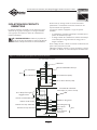
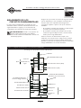
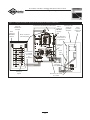
The illustration in Figure 1 depicts the Home Generator
System and assumes the utility is supplying 120/240 Volt,
single-phase electrical service.
Figure 1 — Typical System Diagram with Essential Circuits
To Utility Power
Watt Meter
Main Distribution Panel
To Air Conditioner (240V)
To Other Circuits (120V)
To Range
To Water Heater
240V
To Briggs & Stratton
Home Generator Unit
120V To Microwave
120 V To Bathroom
240V To Well Pump
120V To Sump Pump
Neutral
120V
To Furnace Blower
To Lights
To Refrigerator
120V To Freezer
Automatic Transfer Switch
(in normal position)

7
Briggs & Stratton Power Products Automatic Transfer Switch
Installation and Owner’s Manual
Mounting Guidelines
The Model 01917 Automatic Transfer Switch is enclosed in
a NEMA Type 1 enclosure suitable for indoor use only.
The Model 01918 Automatic Transfer Switch is enclosed in
a NEMA Type 3R enclosure suitable for indoor/outdoor
use.
Guidelines for mounting the Automatic Transfer Switch
include:
• Model 01918 Automatic Transfer Switch must be installed
with minimum NEMA 3R hardware for conduit
connections.
• Install the switch on a firm, sturdy supporting structure.
• To prevent switch contact distortion, level and plumb the
enclosure.This can be done by placing washers between
the switch enclosure and the mounting surface.
• NEVER install the switch where any corrosive substance
might drip onto the enclosure.
• Protect the switch at all times against excessive moisture,
dust, dirt, lint, construction grit and corrosive vapors.
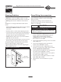
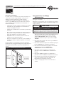
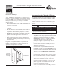
The typical installation of the Automatic Power Transfer
Switch is depicted in Figure 2. Discuss layout
suggestions/changes with the owner before beginning the
system installation process.
Power Wiring Interconnections
All wiring must be the proper size, properly supported, of
approved insulation qualities, and protected by NEC
approved conduit.
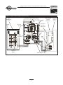
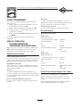
Complete the following connections between the
generator, transfer switch and main distribution panel
(Figure 3, on next page).
1. Connect utility power supply leads from a two pole
breaker installed in the main distribution panel to
transfer switch terminals marked “UTILITY
CONNECTION”. Use a 50 Amp circuit breaker.
Ensure breaker is turned OFF.
2. Connect main distribution panel ground to the transfer
switch “GND” bus.
3. Connect main distribution panel neutral lead to
transfer switch “NEUTRAL” terminal.
4. Connect generator power supply leads from the
generator’s control panel to transfer switch terminals
marked “GENERATOR CONNECTION”.
5. Connect generator Neutral from the control panel to
the transfer switch “NEUTRAL” terminal.
6. Connect generator “GND” from the control panel to
the transfer switch “GND” terminal.
7. Connect generator utility 240V terminals to transfer
switch utility 240V terminals.
8. Tighten all wire connections/fasteners to proper
torque.
• Failure to follow above warning could cause damage and/or
malfunction of equipment.
Per NEC code, low voltage wire cannot be installed in
same conduit as power voltage wiring.
CAUTION
Automatic
Transfer Switch
Main
Distribution
Panel
Figure 2 — Typical Switch Mounting

8
Briggs & Stratton Power Products Automatic Transfer Switch
Installation and Owner’s Manual
Generator
Neutral is
White wire
Utility 240V AC
GND lug
Wire
Nut
Two Pole
Breaker
Utility
Connection
Generator
Connection
Rear of
Control
Panel
Neutral
Bus
Neutral
Bus
Ground
Bus
Main
Distribution
Panel
Automatic Power Transfer Switch
Home Standby
System
Generator
Figure 3 — Typical Installation Diagram for Transfer Switch

9
Briggs & Stratton Power Products Automatic Transfer Switch
Installation and Owner’s Manual
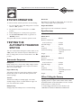
SYSTEM OPERATION
To select automatic transfer operation, do the following:
1. Set circuit breaker that sends utility power to transfer
switch to “On” position.
2. Set generator’s main circuit breaker to its “On”
position.
3. Install 15 Amp fuse in control panel on generator.
4. Set AUTO/OFF/MANUAL switch on generator to
“AUTO” position.
The system will now be in automatic operation mode.
TESTING THE
AUTOMATIC TRANSFER
SWITCH
Turn the circuit breaker feeding the transfer switch, to the
“Off” position.The automatic sequence will follow.To go
back to utility power, turn the circuit breaker to the “On”
position.
Automatic Sequence
Utility Fail
Utility voltage sensor senses when utility voltage is below
70 percent of nominal. Engine start sequence is initiated
after 6 second time delay.
Engine Warm-Up
Time delay to allow for engine warm-up before transfer
fixed at 20 seconds or 50 seconds with optional cold
weather package.
Transfer
Transfers from utility to standby supply occurs after
standby voltage is above set levels. Minimum engine run
time is 4 minutes after transfer.
Utility Pickup
Voltage pickup level is 80 percent of nominal voltage.
Retransfer
Retransfer from standby to utility supply 10 seconds after
utility voltage supply is above pickup level.
Engine Cool Down
Engine will run for 60 seconds after retransfer.
Specifications
UL® 1008 Listed Transfer Switch
Model 01917
Enclosure. . . . . . . . . . . . . . . . . . . NEMA 1
Maximum Load/Circuit:
from Load Center . . . . . . . . . . 50 Amps
Rated AC Voltage. . . . . . . . . . . . . 250 Volts
Poles . . . . . . . . . . . . . . . . . . . . . . 2
Frequency . . . . . . . . . . . . . . . . . . 50/60 Hz
Fault Current Rating . . . . . . . . . . 5,000 RMS Symmetrical
Amperes
Weight . . . . . . . . . . . . . . . . . . . . . 27 lbs.
Model 01918
Enclosure. . . . . . . . . . . . . . . . . . . NEMA 3R
Maximum Load/Circuit:
from Load Center . . . . . . . . . . 50 Amps
Rated AC Voltage. . . . . . . . . . . . . 250 Volts
Poles . . . . . . . . . . . . . . . . . . . . . . 2
Frequency . . . . . . . . . . . . . . . . . . 50/60 Hz
Fault Current Rating . . . . . . . . . . 5,000 RMS Symmetrical
Amperes
Weight . . . . . . . . . . . . . . . . . . . . . 34 lbs.
When Calling the Factory
Before contacting Briggs and Stratton Power Products
regarding service or repair of this transfer switch, obtain
the Model Number and Serial Number from the unit data
decal located on or inside the case.
To contact Briggs and Stratton Power Products call
1-800-743-4115, between 8:00 AM and 5:00 PM CT.

10
Briggs & Stratton Power Products Automatic Transfer Switch
Installation and Owner’s Manual
NOTES

11
Briggs & Stratton Power Products Automatic Transfer Switch
Installation and Owner’s Manual
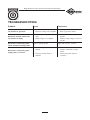
TROUBLESHOOTING
Problem Cause Correction
Automatic transfer switch does
not transfer to generator
1. Generator breaker open.
2. Generator voltage not acceptable.
1. Reset generator circuit breaker.
2. Refer to generator manual.
Automatic transfer switch does
not transfer to utility
1. Main distribution panel breaker
open.
2. Utility voltage not acceptable.
1. Reset main distribution panel
breaker.
2. Wait for utility voltage to return to
normal.
Generator is still running after
switch transfers to utility power
Engine cool down period.
Engine will stop after 1 minute.
Generator is still running after
utility power is restored
1. Minimum engine run time has not
elapsed.
2. Fuse(s) in transfer switch is
defective.
1. Wait five minutes for transfer
switch to retransfer to utility
power.
2. Check fuse(s) and replace if
necessary.

12
Briggs & Stratton Power Products Automatic Transfer Switch
Installation and Owner’s Manual
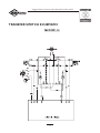
TRANSFER SWITCH SCHEMATIC

13
Briggs & Stratton Power Products Automatic Transfer Switch
Installation and Owner’s Manual
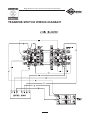
TRANSFER SWITCH WIRING DIAGRAM

14
Briggs & Stratton Power Products Automatic Transfer Switch
Installation and Owner’s Manual
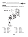
TRANSFER SWITCH EXPLODED VIEW & PARTS LIST
Item Part # Description
1 NSP LOADCENTER
2 192909GS BOARD, Control
3 192151GS HOLDER, Fuse
4 190984GS DECAL, Fuse
5 192597GS DECAL, Utility, 240 VAC
6 193626GS TAPTITE, #6 - 32 x 5/8"
7 B4854GS TERMINAL, SLS, 14-6 AWG
8 189916GS BAR, BUS, Copper
9 194205GS TAPTITE, #8 - 32 x 5/8"
10 185891GS RELAY, 50A
11 193239GS TAPTITE, #6-32 x 1/4"
Item Part # Description
12 B4857GS FUSE, 2A
13 190983GS DECAL,Torque
14 190982GS DECAL, Lug
15 192701GS SPACER, 5/16" OD
16 190992GS DECAL,Warning
17 192707GS DECAL, 50A,ATS
18 192708GS DECAL, Identification
19 190850GS DECAL,ATS, BSPP
20 B5106GS DECAL, Utility Connection
21 B5107GS DECAL, Gen. Connection
23 198161GS COVER, Load Center w/ Decals
MODEL 01917
NEMA 1

15
Briggs & Stratton Power Products Automatic Transfer Switch
Installation and Owner’s Manual
TRANSFER SWITCH EXPLODED VIEW & PARTS LIST
Item Part # Description
1 NSP LOADCENTER
2 192909GS BOARD, Control
3 192151GS HOLDER, Fuse
4 190984GS DECAL, Fuse
5 192597GS DECAL, Utility, 240VAC
6 193626GS TAPTITE, #6 - 32 x 5/8"
7 B4854GS TERMINAL, SLS, 14-6 AWG
8 189916GS BAR, BUS, Copper
9 194205GS TAPTITE, #8 - 32 x 5/8"
10 185891GS RELAY, 50A
11 193239GS TAPTITE, #6-32 x 1/4"
Item Part # Description
12 B4857GS FUSE, 2A
13 190983GS DECAL,Torque
14 190982GS DECAL, Lug
15 192701GS SPACER, 5/16" OD
16 190992GS DECAL,Warning
17 192713GS DECAL, 50A,ATS
18 192714GS DECAL, Identification
19 190850GS DECAL,ATS, BSPP
20 B5106GS DECAL, Utility Connection
21 B5107GS DECAL, Gen. Connection
MODEL 01918
NEMA 3R

16
Briggs & Stratton Power Products Automatic Transfer Switch
Installation and Owner’s Manual
NOTES

BRIGGS & STRATTON POWER PRODUCTS GROUP, LLC EQUIPMENT OWNER WARRANTY POLICY
LIMITED WARRANTY
Briggs & Stratton Power Products Group, LLC will repair or replace, free of charge, any part(s) of the equipment that is defective in material
or workmanship or both. Transportation charges on parts submitted for repair or replacement under this warranty must be borne by
purchaser. This warranty is effective for the time periods and subject to the conditions stated below. For warranty service, find the nearest
Authorized Service Dealer in our dealer locator map at www.briggspowerproducts.com.
THERE IS NO OTHER EXPRESS WARRANTY. IMPLIED WARRANTIES, INCLUDING THOSE OF MERCHANTABILITY AND FITNESS
FOR A PARTICULAR PURPOSE, ARE LIMITED TO ONE YEAR FROM PURCHASE, OR TO THE EXTENT PERMITTED BY LAW ANY
AND ALL IMPLIED WARRANTIES ARE EXCLUDED. LIABILITY FOR INCIDENTAL OR CONSEQUENTIAL DAMAGES ARE EXCLUDED
TO THE EXTENT EXCLUSION IS PERMITTED BY LAW. Some states or countries do not allow limitations on how long an implied warranty
lasts, and some states or countries do not allow the exclusion or limitation of incidental or consequential damages, so the above limitation
and exclusion may not apply to you. This warranty gives you specific legal rights and you may also have other rights which vary from state
to state or country to country.
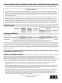
OUR EQUIPMENT*
OUTBOARD
MOTOR
PRESSURE
WASHER
WATER PUMP
(Not available in the
USA)
PORTABLE
GENERATOR
WELDER
LLeessss tthhaann 1100 KKWW 1100 KKWW oorr ggrreeaatteerr
TTrraannssffeerr sswwiittcchh
2 years
none
1 year
90 days
1 year
90 days
2 years
1 year
2 years
none
3 years or
1500 hours
none
3 years
none
WARRANTY PERIOD**
HOME STANDBY GENERATOR SYSTEM
Consumer Use
Commercial Use
* The engine and starting batteries are warranted solely by the manufacturers of those products.
** 2 years for all consumer products in the European Union. Parts only on 2nd year for consumer use of Portable Generator and
Home Standby Generator System - Less than 10 KW, outside of European Union.
The warranty period begins on the date of purchase by the first retail consumer or commercial end user, and continues for the period of time
stated in the table above. “Consumer use" means personal residential household use by a retail consumer. “Commercial use" means all other
uses, including use for commercial, income producing or rental purposes. Once equipment has experienced commercial use, it shall thereafter
be considered as commercial use for purposes of this warranty. Equipment used for prime power in place of utility are not applicable to
this warranty. Electric powered pressure washers used for commercial purposes are not warranted.
NO WARRANTY REGISTRATION IS NECESSARY TO OBTAIN WARRANTY ON BRIGGS & STRATTON PRODUCTS. SAVE YOUR
PROOF OF PURCHASE RECEIPT. IF YOU DO NOT PROVIDE PROOF OF THE INITIAL PURCHASE DATE AT THE TIME WARRANTY
SERVICE IS REQUESTED, THE MANUFACTURING DATE OF THE PRODUCT WILL BE USED TO DETERMINE THE WARRANTY
PERIOD.
ABOUT YOUR WARRANTY
We welcome warranty repair and apologize to you for being inconvenienced. Any Authorized Service Dealer may perform warranty repairs. Most
warranty repairs are handled routinely, but sometimes requests for warranty service may not be appropriate. For example, warranty service would not
apply if equipment damage occurred because of misuse, lack of routine maintenance, shipping, handling, warehousing or improper installation.
Similarly, the warranty is void if the manufacturing date or the serial number on the equipment has been removed or the equipment has been altered
or modified. During the warranty period, the Authorized Service Dealer, at its option, will repair or replace any part that, upon examination, is found to
be defective under normal use and service. This warranty will not cover the following repairs and equipment:
• Normal Wear: Outdoor Power Equipment, like all mechanical devices, needs periodic parts and service to perform well. This warranty does not
cover repair when normal use has exhausted the life of a part or the equipment.
• Installation and Maintenance: This warranty does not apply to equipment or parts that have been subjected to improper or unauthorized
installation or alteration and modification, misuse, negligence, accident, overloading, overspeeding, improper maintenance, repair or storage so as,
in our judgment, to adversely affect its performance and reliability. This warranty also does not cover normal maintenance such as adjustments,
fuel system cleaning and obstruction (due to chemical, dirt, carbon, lime, etc.).
• Other Exclusions: This warranty excludes wear items such as quick couplers, oil gauges, belts, o-rings, filters, pump packing, etc., pumps that
have been run without water supplied or damage or malfunctions resulting from accidents, abuse, modifications, alterations, or improper servicing
or freezing or chemical deterioration. Accessory parts such as guns, hoses, wands and nozzles are excluded from the product warranty. This
warranty excludes failures due to acts of God and other force majeure events beyond the manufacturers control. Also excluded is used,
reconditioned, and demonstration equipment; equipment used for prime power in place of utility power and equipment used in life support
applications.
BRIGGS & STRATTON POWER PRODUCTS GROUP, LLC
JEFFERSON, WI, USA
Effective September 1, 2004 replaces all undated Warranties and all Warranties dated before September 1, 2004

18
Commutateur de transfert automatique Briggs & Stratton Power Products
Guide d'installation et d'utilisation
TABLE DES MATIÈRES. . . . . . . . . . . . . . . . . . . . . . . . . . . . . . . . . 18
RÈGLES DE SÉCURITÉ . . . . . . . . . . . . . . . . . . . . . . . . . . . . . . . . 19
INTRODUCTION . . . . . . . . . . . . . . . . . . . . . . . . . . . . . . . . . . . . 20
Au Propriétaire Résidentiel . . . . . . . . . . . . . . . . . . . . . . . . . 20
Au Détaillant/à l'Entrepreneur Procédant à
l'Installation. . . . . . . . . . . . . . . . . . . . . . . . . . . . . . 20
Conseils au Propriétaire. . . . . . . . . . . . . . . . . . . . . . . . . . . . 20
Responsabilités de l'Installateur . . . . . . . . . . . . . . . . . . . . . . 20
Description de l'Équipement . . . . . . . . . . . . . . . . . . . . . . . . 21
INSTALLATION . . . . . . . . . . . . . . . . . . . . . . . . . . . . . . . . . . . . . . 21
Déballage . . . . . . . . . . . . . . . . . . . . . . . . . . . . . . . . . . . . . . . 21
Vérification de la Livraison. . . . . . . . . . . . . . . . . . . . . . 21
Contenu de la Boîte . . . . . . . . . . . . . . . . . . . . . . . . . . . 21
ISOLATION DES CIRCUITS ESSENTIELS . . . . . . . . . . . . . . . . . 22
Instructions d'Installation . . . . . . . . . . . . . . . . . . . . . . . . . . . 23
Interconnexions du Câblage d'Alimentation . . . . . . . . . 23-24
FONCTIONNEMENT . . . . . . . . . . . . . . . . . . . . . . . . . . . . . . . . . 25
MISE À L'ESSAI DU COMMUTATEUR DE TRANSFERT
AUTOMATIQUE . . . . . . . . . . . . . . . . . . . . . . . . . . . . . 25
Séquence Automatique. . . . . . . . . . . . . . . . . . . . . . . . . . . . . 25
Panne de l'alimentation de service . . . . . . . . . . . . . . . 25
Réchauffement du moteur . . . . . . . . . . . . . . . . . . . . . . 25
Transfert . . . . . . . . . . . . . . . . . . . . . . . . . . . . . . . . . . . 25
Prise en charge de l'alimentation de service. . . . . . . . 25
Retransfert . . . . . . . . . . . . . . . . . . . . . . . . . . . . . . . . . . 25
Refroidissement du moteur . . . . . . . . . . . . . . . . . . . . . 25
Caractéristiques . . . . . . . . . . . . . . . . . . . . . . . . . . . . . . . . . . 25
Commutateur de Transfert . . . . . . . . . . . . . . . . . . . . . 25
Modèle 01917. . . . . . . . . . . . . . . . . . . . . . . . . . . . . . . . 25
Modèle 01918. . . . . . . . . . . . . . . . . . . . . . . . . . . . . . . . 25
Si vous Devez Communiquer avec l'Usine . . . . . . . . . . . . . 25
REMARQUES. . . . . . . . . . . . . . . . . . . . . . . . . . . . . . . . . . . . 26 & 28
DÉPANNAGE . . . . . . . . . . . . . . . . . . . . . . . . . . . . . . . . . . . . . . . . 27
SCHÉMAS,VUES ÉCLATÉES, LISTES DES PIÈCES. . . . . . . . . 12-15
GARANTIE. . . . . . . . . . . . . . . . . . . . . . . . . . . . . . . . . . . . . . . . . . 29
TABLE DES MATIÈRES

19
Commutateur de transfert automatique Briggs & Stratton Power Products
Guide d'installation et d'utilisation
DIRECTIVES DE SÉCURITÉ
IMPORTANTES
Ceci est la sûreté le symbole vif. Il est utilisé pour
vous alerter aux dangers de blessure personnels
potentiels. Obéir tous messages de sûreté qui
suivent ce symbole éviter la blessure ou la mort
possibles.
Le symbole indiquant un message de sécurité est accompagné
d'un mot indicateur (DANGER,ATTENTION,AVERTISSEMENT),
d'un message illustré et/ou d'un message de sécurité visant à vous
avertir des dangers. DANGER indique un danger qui, s'il n'est pas
évité, provoquera des blessures graves, voire fatales.
AVERTISSEMENT indique un danger qui, s'il n'est pas évité,
peut provoquer des blessures graves, voire fatales. ATTENTION
indique un danger qui, s'il n'est pas évité, peut provoquer des
blessures mineures ou légères. Le mot ATTENTION, lorsqu'il
est utilisé sans le symbole d'alerte, indique une situation pouvant
endommager l'équipement. Suivez les messages de sécurité pour
éviter ou réduire les risques de blessures ou de mort.
Le fabriquant ne peut anticiper toutes les circonstances
potentielles pouvant comporter un danger. Par conséquent, les
avertissements contenus dans le présent manuel, ainsi que les
plaques et les décalques apposés sur l'unité n'englobent pas toutes
les possibilités. Si vous utilisez une procédure, une méthode de
travail ou une technique d'opération non spécifiquement
recommandée par le fabricant, vous devez vous assurer qu'elle ne
compromet pas votre sécurité ni celle des autres.Vous devez
également vous assurer que la procédure, la méthode de travail
ou la technique d'opération que vous choisissez ne rende pas la
commutateur de transfert dangereuse.
Seuls les électriciens qualifiés peuvent procéder à l'installation
de ce système, laquelle doit se conformer strictement aux
codes, aux normes et aux réglementations applicables.
AVERTISSEMENT
• NE touchez PAS les fils dénudés ou les boîtiers.
• N'utilisez PAS le commutateur de transfert avec des cordons
électriques usés, effilochés ou dénudés, ou abîmés de quelque sorte
que ce soit.
• NE manipulez PAS les cordons d'alimentation lorsque vous êtes
debout dans l'eau, pieds nus ou avec les mains ou les pieds humides.
• Si vous devez travaillez autour d'une unité alors qu'elle est en marche,
placez-vous sur une surface sèche isolée afin de réduire les risques de
choc électrique.
• NE laissez PAS des personnes non qualifiées ou des enfants se servir
ou réparer le commutateur de transfert.
• En cas d'accident causé par un choc électrique, procédez
immédiatement à la mise hors tension de l'alimentation électrique et
contacter des autorités locales. Évitez tout contact direct avec la
victime.
NE PAS relier le commutateur de transfert à la terre
risque de provoquer des électrocutions.
AVERTISSEMENT
• Ne vous servez du commutateur de transfert que pour les utilisations
prévues.
• Si vous avez des questions concernant les utilisations prévues,
demandez à votre distributeur ou contactez Briggs and Stratton
Power Products.
• N'exposez PAS le commutateur de transfert à une humidité excessive,
à de la poussière, à de la saleté ou à des vapeurs corrosives.
• Demeurez alerte en tout temps lorsque vous travaillez sur cet
équipement. NE travaillez JAMAIS sur l'équipement si vous êtes fatigué
physiquement ou mentalement.
• Si les appareils branchés surchauffent, éteignez-les et mettez leur
disjoncteur ou fusible hors tension.
Un traitement inapproprié du commutateur de transfert risque
de l'endommager et de raccourcir sa durée d'utilisation.
ATTENTION
• Le non-respect de cet avertissement pourrait entraîner des blessures
personnelles et l'endommagement ou le mauvais fonctionnement de
l'équipement.
Les fils de basse tension ne peuvent être installés
dans le même conduit que les fils d’alimentation.
AVERTISSEMENT
• En dépit de la conception sécuritaire du commutateur de transfert, le
fait d'opérer l'équipement de façon imprudente, de ne pas l'entretenir
ou d'être négligent peut causer des blessures et la mort.
Le commutateur de transfert contient une haute
tension qui peut causer des blessures personnelles ou
la mort.
AVERTISSEMENT
VEUILLEZ CONSERVER CES INSTRUCTIONS

20
Commutateur de transfert automatique Briggs & Stratton Power Products
Guide d'installation et d'utilisation
INTRODUCTION
Nous vous remercions d'avoir acheté ce commutateur de
transfert automatique de Briggs & Stratton Power Products
(BSPP). Ce commutateur de transfert convient UNIQUEMENT
aux génératrices de secours résidentielles Briggs & Stratton. Ce
produit est conçu pour être utilisé comme groupe électrogène
optionnel fournissant une source d'électricité alternative et pour
desservir des charges comme le chauffage, les systèmes de
réfrigération et les systèmes de communication qui, lorsqu'ils sont
arrêtés durant une panne d'électricité, peuvent causer des
inconforts ou autre. Ce produit ne se qualifie pas comme groupe
électrogène d'urgence tel que défini par la NFPA 70 (NEC).
La société Briggs & Stratton Power Products (BSPP) a tout fait
pour fournir un commutateur de transfert dont l'installation soit
sécuritaire, facile et économique. Comme chaque installation est
unique, il est impossible de connaître et de recommander une
marche à suivre présentant toutes les méthodes et consignes
d'installation possibles. Briggs et Stratton ignore également les
dangers et/ou les résultats potentiels de chaque méthode ou
procédure. C'est pourquoi,
Seuls des entrepreneurs en électricité qualifiés devraient
procéder à l'installation des commutateur de transfert.
Toute installation doit être conforme à tous codes de
sécurité applicables, ainsi qu'aux normes et à la
réglementation de l'industrie.
Votre commutateur de transfert BSPP est livré avec le présent
"Guide d'installation et d'utilisation". Ce guide est un document
important; conservez-le après avoir complété l'installation.
Tout a été fait pour s'assurer que les renseignements contenus
dans le présent guide soient exacts et à jour.Toutefois, le
fabriquant se réserve le droit de changer, de modifier ou encore
d'améliorer le système en tout temps, et ce, sans préavis.
Au Propriétaire Résidentiel
Afin de vous aider à faire des choix avisés et à communiquer
efficacement avec l'entrepreneur qui procédera à l'installation,
Veuillez lire avec soin la section Conseils au propriétaire
dans le présent guide avant de contracter un
entrepreneur ou de commencer l'installation de votre
commutateur de transfert.
Pour assurer une installation adéquate, veuillez contacter le
magasin qui vous a vendu votre commutateur de transfert Briggs
& Stratton Power Products, votre détaillant ou votre fournisseur
de services d'électricité.
Si l'installation du commutateur de transfert n'est pas
effectuée par des professionnels certifiés en
électricité, la garantie sera ANNULÉE
.
Au Détaillant ou à l'Entrepreneur
Procédant à l'Installation
Le présent guide contient tous les renseignements nécessaires
à l'installation adéquate du commutateur de transfert pour la
plupart des usages.
Si vous avez besoin de renseignements supplémentaires,
veuillez appeler au (800) 743-4115 de 8 h à 17 h HNC.
Conseils au Propriétaire
Les illustrations se rapportent à des cas typiques et ont pour but
de vous familiariser avec les différentes options d'installation de
votre commutateur de transfert dont vous disposez.
Au moment de négocier avec un installateur professionnel, il
faudra tenir compte des facteurs suivants : les codes de sécurité
locaux, l'apparence, le niveaux de bruits, et les distances.
Souvenez-vous que plus grandes sont les distances entre le groupe
électrogène et le service électrique existant ainsi que
l'alimentation, plus il faudra faire des compensations dans les
matériaux et le câblage. Ces modifications sont nécessaires pour
vous conformer aux codes de sécurité locaux et pour surmonter
les chutes de tension.
Les facteurs mentionnés ci-dessus auront une incidence
directe sur le prix total de l'installation de votre
commutateur de transfert.
REMARQUE: Votre installateur est tenu de vérifier les codes
locaux ET d'obtenir les permis requis avant de procéder à
l'installation du système.
• Vous devez lire et suivre les instructions indiquées dans le
manuel.
• Établissez un programme d'entretien, de soins et d'utilisation
régulier de votre commutateur de transfert, tel qu'indiqué
dans le manuel.
La page est en cours de chargement...
La page est en cours de chargement...
La page est en cours de chargement...
La page est en cours de chargement...
La page est en cours de chargement...
La page est en cours de chargement...
La page est en cours de chargement...
La page est en cours de chargement...
La page est en cours de chargement...
La page est en cours de chargement...
La page est en cours de chargement...
La page est en cours de chargement...
La page est en cours de chargement...
La page est en cours de chargement...
La page est en cours de chargement...
La page est en cours de chargement...
La page est en cours de chargement...
La page est en cours de chargement...
La page est en cours de chargement...
La page est en cours de chargement...
-
 1
1
-
 2
2
-
 3
3
-
 4
4
-
 5
5
-
 6
6
-
 7
7
-
 8
8
-
 9
9
-
 10
10
-
 11
11
-
 12
12
-
 13
13
-
 14
14
-
 15
15
-
 16
16
-
 17
17
-
 18
18
-
 19
19
-
 20
20
-
 21
21
-
 22
22
-
 23
23
-
 24
24
-
 25
25
-
 26
26
-
 27
27
-
 28
28
-
 29
29
-
 30
30
-
 31
31
-
 32
32
-
 33
33
-
 34
34
-
 35
35
-
 36
36
-
 37
37
-
 38
38
-
 39
39
-
 40
40


Briggs & Stratton 01918-0 Manuel utilisateur
- Taper
- Manuel utilisateur
- Ce manuel convient également à
dans d''autres langues
Documents connexes
-
Briggs & Stratton 01917-0 Le manuel du propriétaire
-
-
-
-
-
-
-
Briggs & Stratton 71002 Le manuel du propriétaire