DSBA3305 • Rév. 19/10/2020 • Evol. EV-20-85
6
FR
Modèles POSI-BBPR (GPS)
SNBA150000
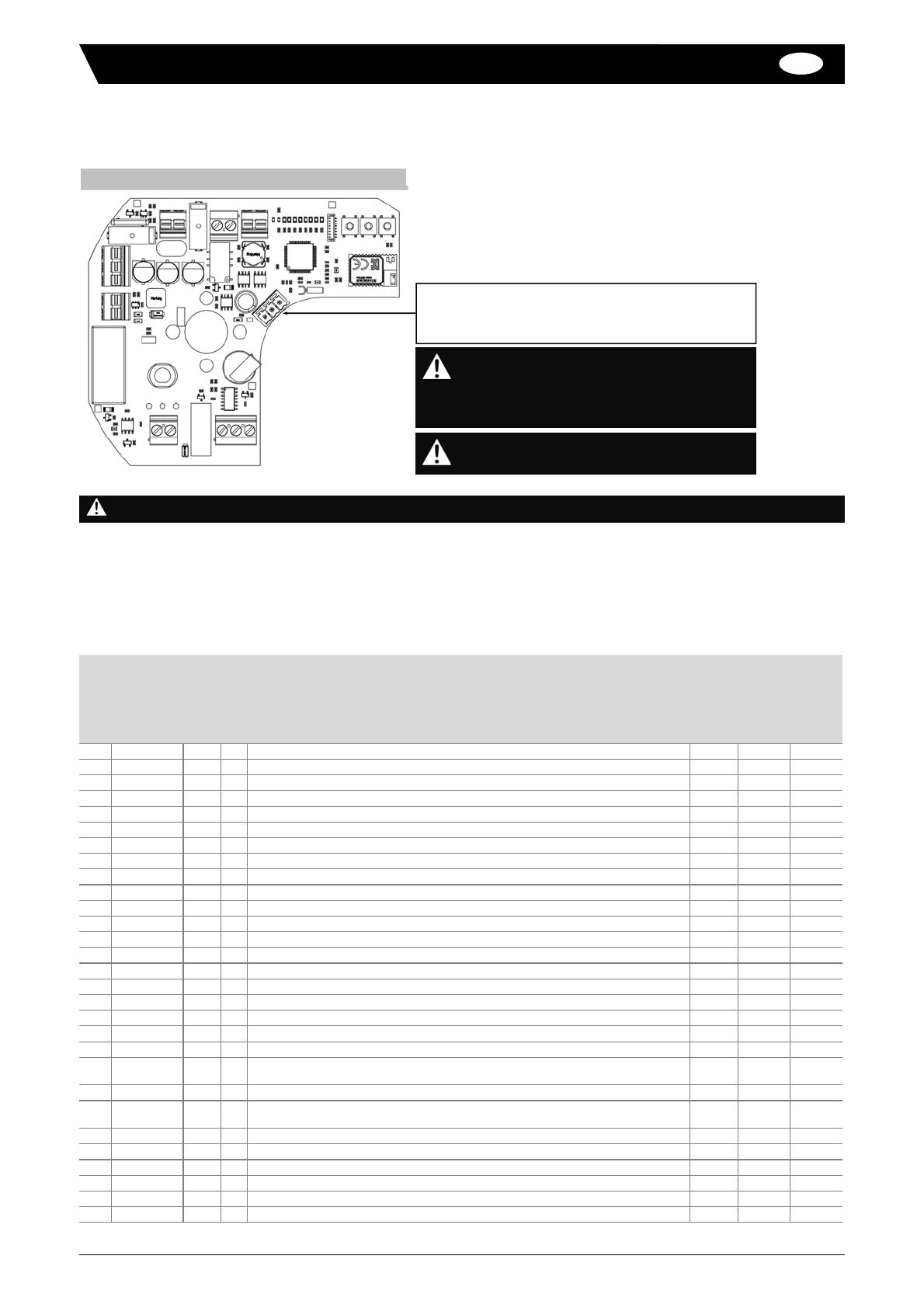
Raccordement électrique
Connecter le câble de communication MODBUS sur le bornier RS485 (
0-A-B
) de la carte GPS
Connecter le câble d’alimentation sur les bornes 1 et 3 du bornier d’alimentation (
Ca
) de la carte d’alimentation (voir page 4) :
1 : neutre (50/60 Hz) ou négatif (DC)
3 : phase (50/60 Hz) ou positif (DC)
Registre
Fonction
R/W
Bytes
Description
Valeur
min.
Valeur par
défaut
Valeur
max.
1 0x03 R 2 Version du logicilel 0 0 65535
9 0x03 / 0x10 R/W 2 Adresse de l’actionneur 1 247 247
12 0x03 R 2 Rampe de démarrage (unité : 0,1 s) 0 5 20
21 0x03 R 2 Retard de détection de surcouple (unité : 0,1 s) 0 10 20
22 0x03 R 2 Limiteur de couple (%) 10 100
27 0x03 R 2 Déblocage après surcouple (unité : 0,1 s) 0 10 20
30 0x03 R 2 Température de sécurité (°C) 40 70 150
34 0x03 R 2 Température minimum enregistrée -20 127
35 0x03 R 2 Température maximum enregistrée 0 150
36 0x03 R 2 Température actuelle (unité : 0,1 °C) -200 1270
42 0x03 / 0x10 R/W 2 BBPR position par défaut (“ouvert”= 1 ; “Inactif”= 4 ; “fermé”= 2) 1 2 4
50 0x03 / 0x10 R/W 2 Type de signal de consigne (“0_10 V”= 1 ; “4_20 mA”= 2) 1 2 2
51 0x03 / 0x10 R/W 2 Inversion du signal de consigne (“normal”= 1 ; “Inversé”= 2) 1 1 2
60 0x03 / 0x10 R/W 2 Type de signal de recopie (“0_10V”= 1 ; “4_20 mA”= 2) 1 2 2
61 0x03 / 0x10 R/W 2 Inversion du signal de recopie (“normal”= 1 ; “Inversé”= 2) 1 1 2
62 0x06 W 2 Consigne (unité : 0,1 %) (Mode manuel seulement) 0 1000
63 0x03 R 2 Recopie (unité : 0,1%) 0 1000
90 0x03 R 2 Statut du système BBPR (“non disponible”= 0 ; “disponible”=1) 0 1 1
91 0x03 R 2 Niveau de charge de la batterie (“HS”= 1 ; “En charge”= 2 ; “3 et 4”= Chargée) 1 4
92 0x03 R 2 Report défaut (“non activé”= 0 ; “activé”= 1) 0 0 1
100 0x03 / 0x06 R/W 2 Mode actuel (“manuel”= 0x01 ; “POSI”= 0x02 ; “Prog.”= 0x04 ;
“apprentissage”= 0x16 ; “BBPR”= 0x64) 1 2 64
102 0x03 R 2 Position (“ouverture”= 7 ; “fermeture”= 8 ; “stop”= 4 ; “surcoulple”= 10) 4 10
103 0x03 R 2 Position (“ouvert”= 0x01 ; “ouverture”= 0x17 ; “fermé”= 0x02 ;
“fermeture”= 0x18 ; “stop”= 0x04 ; “surcoulple”= 0x16) 1 18
120 0x03 R 2 Nombre de cycles 0 0 65535
122 0x03 R 2 Nombre d’erreurs 0 0 65535
123 0x03 R 2 Nombre de coupures électriques 0 0 65535
124 0x03 R 2 Temps de fonctionnement (heures) 0 65535
125 0x03 R 2 Temps de fonctionnement (minutes) 0 59
126 0x03 R 2 Temps de fonctionnement (secondes) 0 59
Connecteur RS485 (liaison série) pour communication
MODBUS-RTU
Pour le dernier actionneur de la ligne (voir
schéma p.3), il est nécessaire de connecter une
résistance de terminaison de 120 Ω (fournie)
entre les bornes A et B.
Pour que l’actionneur puisse être piloté, il doit
être en mode « manuel » (par défaut)
Pour toute information supplémentaire, se reporter au manuels des actionneurs
Table de registres


