
WHI
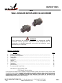
WALL HUGGER INVISIFLAME® GAS BURNER
TABLE OF CONTENTS
Subject Page
A. General Information ……………………………………………………….…..….……. 2
B. Receiving and Inspection ………………………………………….…….…...…….….. 2
C. Capacities ………….……………………………………………………………………. 3
D. Dimensions …………….………………………………………………………………... 7
E. Installation ……………………………………………………………………………….. 7
F. Ignition…………………………………………………………………………………….. 10
G. Initial SetUp………………………………………………………………………………. 11
H. Operation…………………………………………………………………………………. 14
I. Maintenance……………………………………………………………………………… 14
J. Recommended Spare Parts……………………………………………………………. 16
Attachments: ZMI Ionization Pilot
IC20 Butterfly Valve Actuator
INSTRUCTIONS
WARNING
These instructions are intended for use only by experienced, qualified
combustion start-up personnel. Adjustment of this equipment and its
components, by unqualified personnel, can result in fire, explosion, severe
personal injury, or even death.
These instructions are intended to serve as
guidelines covering the installation, operation, and maintenance of Hauck equipment. While
every attempt has been made to ensure completeness, unforeseen or unspecified applications, details, and variations may preclude
covering every possible contingency.
WARNING: TO PREVENT THE POSSIBILITY OF SERIOUS BODILY INJURY, DO NOT USE OR
OPERATE ANY EQUIPMENT OR COMPONENT WITH ANY PARTS REMOVED OR ANY PARTS NOT APPROVED BY THE
MANUFACTURER. Should further information be required or desired or should particular pr
oblems arise which are not covered
sufficiently for the purchaser’s purpose, contact Hauck Mfg. Co.
WHI-9
HAUCK MANUFACTURING CO.,
P.O. Box 90 Lebanon, PA 17042-0090 717-272-3051
6/11 www.hauckburner.com Fax: 717-273-9882

Page 2
WHI-9
A. GENERAL INFORMATION
The WHI burner utilizes an air-staged design for ultra low NOx emissions and low CO when firing
with low excess air in furnace environments with temperatures up to 2500°F (1,370°C). The
burner has two modes of operation, ‘firing’ mode required for low temperature startup or operation
below 1600°F (870°C), and Invisiflame® mode for ultra low NOx operation above 1600°F
(870°C). Transitioning between modes is accomplished via a switching valve which is sold
separately. The burner operates with cold or preheated air up to 900°F (480°C).
The WHI burners fire any clean industrial fuel gas. Capacities range from 2 to 6 MM Btu/Hr (580 –
1,760 kW) at 20.9"wc (5200 Pa) static air pressure. The burner is designed for applications
requiring even heat distribution with no flame impingement at all firing rates.
Turndown is approximately 10:1 on natural gas. Consult Hauck for mounting options and field
installation recommendations.
B. RECEIVING & INSPECTION
Upon receipt, check each item on the bill of lading and/or invoice to determine that all equipment
has been received. A careful examination of all parts should be made to ascertain if there has
been any damage in shipment.
WARNING
This equipment is potentially dangerous with the possibility of serious personal injury
and property damage. Hauck Manufacturing Company recommends the use of flame
supervisory equipment and fuel safety shutoff valves. Furthermore, Hauck urges rigid
adherence to National Fire Protection Association (NFPA) standards and insurance
underwriter’s requirements. Operation and regular preventative maintenance of this
equipment should be performed only by properly trained and qualified personnel.
Annual review and upgrading of safety equipment is recommended.
IMPORTANT
If the installation is delayed and the equipment is stored outside,
provide adequate protection as dictated by climate and period of
exposure. Special care should be given to all motors and bearings, if
applicable, to protect them from rain or excessive moisture.
WARNING
The WHI burner MUST be equipped with the Invisiflame control valve and actuator for
operation in furnaces < 1,600°F. Refer to the burner capacity sheets for operating air
pressure required, Stage 1 & 2 Static Air Pressure, when using the Invisiflame control
valve. If equipped without the Invisiflame control valve, the burner can only be fired >
1,600°F furnace temperature.

Page 3
WHI-9
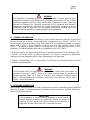
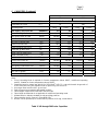
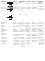
C. CAPACITIES
BURNER MODEL
140 240
BURNER SPECIFICATIONS – HIGH FIRE BURNER STATIC INLET AIR PRESSURE OF 20.9"WC
Combustion Air Temp. (°F) 60 900
Operating Mode
Firing Invisi-
Flame
Firing Invisi-
Flame
Max. Input @ 5% Excess Air (MMBtu/hr) 2.4
2.0
1.5
1.2
Max. Air Flow @ 20.9"wc (scfh) 24,000
19,500
14,840
11,760
Min. Input @ Max. Air Flow (Btu/hr) 191,000
N/A
Max. Excess Air (%) 1,230
N/A
Air Press. @ Burner Inlet ("wc) 22.5
22.5
22.5
22.5
Burner Gas Inlet Press. ("wc) 7.9
7.0
4.2
2.5
Flame Length @ Max. Input (ft) 0.75
N/A
.5
N/A
Flame Dia. @ Max. Input (ft) 3.5
N/A
2.75
N/A
Stage 1 & 2 Air Static Press. ("wc) 1.7
0.2
1.7
0.2
Stage 3 Air Static Press. ("wc) 7.6
7.7
7.6
7.7
BURNER SPECIFICATIONS – LOW FIRE
Input @ 5% Excess Air (Btu/hr)
151,600
151,600
151,600
151,600
Air Flow – Low Fire (scfh) 1,500
1,500
1,500
1,500
Min. Input @ Low Fire Air Flow (Btu/hr)
80,000
N/A
Max. Excess Air (%) 100
N/A
Min. Gas for Ignition (scfh) 80
80
80
80
Min. Gas for UV Signal (scfh) 80
N/A
80
N/A
Notes:
1. “Firing” Operating Mode is required for furnace temperature below 1600°F; Invisiflame® operating
mode is suitable for furnace temperature above 1600°F.
2. Capacities based on natural gas with HHV of 134 Btu/ft3, 0.59 S.G., and stoichiometric air:gas ratio
of 9.74:1 with burner firing into chamber under no pressure @ 5% excess air.
3. Air and gas flows based on 60°F @ sea level.
4. Static air pressure measured at designated locations.
5. Flame lengths measured from the end of the burner tile.
6. Flame length and diameter is not applicable in Invisiflame® operating mode..
7. All data based on industry standard air and gas piping practices.
8. Flame detection via UV scanner in Firing Mode only.
9. Burners can be operated up to a static inlet air pressure of 16 osig; consult Hauck.
Table 1. 140 through 240 Series Capacities

Page 4
WHI-9
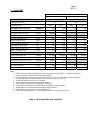
C. CAPACITIES (Continued)
BURNER MODEL
140 240
BURNER SPECIFICATIONS – HIGH FIRE BURNER STATIC INLET AIR PRESSURE OF 5,200 Pa
Combustion Air Temp. (°C) 15.5°C 482°C
Operating Mode
Firing Invisi-
Flame
Firing Invisi-
Flame
Max. Input @ 5% Excess Air (kW) 650
545
410
325
Max. Air Flow @ 5,200 Pa (nm3/hr) 640
520
400
315
Min. Input @ Max. Air Flow (kW) 56
N/A
Max. Excess Air (%) 1,230
N/A
Air Press. @ Burner Inlet (Pa) 5,600
5,600
5,600
5,600
Burner Gas Inlet Press. (Pa) 1,965
1,740
1,045
620
Flame Length @ Max. Input (mm) 230
N/A
150
N/A
Flame Dia. @ Max. Input (mm) 1,070
N/A
840
N/A
Stage 1 & 2 Air Static Press. (Pa) 420
50
420
50
Stage 3 Air Static Press. (Pa) 1,890
1,915
1,890
1,915
BURNER SPECIFICATIONS – LOW FIRE
Input @ 5% Excess Air (kW) 60
60
60
60
Air Flow – Low Fire (nm3/hr) 55
55
55
55
Min. Input @ Low Fire Air Flow (kW)
55
N/A
Max. Excess Air (%) 15
N/A
Min. Gas for Ignition (nm3/hr) 4.7
4.7
4.7
4.7
Min. Gas for UV Signal (nm3/hr) 4.7
N/A
4.7
N/A
Notes:
1. “Firing” Operating Mode is required for furnace temperatures below 870°C; Invisiflame® operating
mode is suitable for furnace temperatures above 870°C.
2. Capacities based on natural gas with LHV of 36.74 MJ/nm3, 0.59 S.G., and stoichiometric air:gas ratio
of 9.74:1 with burner firing into chamber under no pressure @ 5% excess air.
3. Air and gas flows based on 0°C @ sea level.
4. Static air pressure measured at designated locations.
5. Flame lengths measured from the end of the burner tile.
6. Flame length and diameter is not applicable in Invisiflame® operating mode.
7. All data based on industry standard air and gas piping practices.
8. Flame detection via UV scanner in Firing Mode only.
9. Burners can be operated up to a static inlet air pressure of 3450 Pa; consult Hauck.
Table 2. 140 through 240 Series Metric Capacities

Page 5
WHI-9
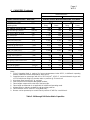
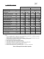
C. CAPACITIES (Continued)
BURNER MODEL
160 260
BURNER SPECIFICATIONS – HIGH FIRE BURNER STATIC INLET AIR PRESSURE OF 20.9"WC
Combustion Air Temp. (°F) 60 900
Operating Mode
Firing Invisi-
Flame
Firing Invisi-
Flame
Max. Input @ 5% Excess Air (MMBtu/hr) 4.9
4.5
3.0
2.8
Max. Air Flow @ 20.9"wc (scfh) 48,430
44,590
29,950
27,570
Min. Input @ Max. Air Flow (Btu/hr) 300,000
N/A
Max. Excess Air (%) 1,600
N/A
Air Press. @ Burner Inlet ("wc) 22.5
22.5
22.5
22.5
Burner Gas Inlet Press. ("wc) 28.6
23.3
13.6
10
Flame Length @ Max. Input (ft) 1
N/A
0.75
N/A
Flame Dia. @ Max. Input (ft) 6
N/A
4.75
N/A
Stage 1 & 2 Air Static Press. ("wc) 2.0
0.1
2.0
0.1
Stage 3 Air Static Press. ("wc) 20.9
20.9
20.9
20.9
BURNER SPECIFICATIONS – LOW FIRE
Input @ 5% Excess Air (Btu/hr)
300,000
300,000
300,000
300,000
Air Flow – Low Fire (scfh) 3,100
3,100
3,100
3,100
Min. Input @ Low Fire Air Flow (Btu/hr)
150,000
N/A
Max. Excess Air (%) 120
N/A
Min. Gas for Ignition (scfh) 145
145
145
145
Min. Gas for UV Signal (scfh) 145
N/A
145
N/A
Notes:
1. “Firing” Operating Mode is required for furnace temperatures below 1600°F; Invisiflame® operating
mode is suitable for furnace temperatures above 1600°F.
2. Capacities based on natural gas with HHV of 1034 Btu/ft3, 0.59 S.G., and stoichiometric air:gas ratio of
9.74:1 with burner firing into chamber under no pressure @ 5% excess air.
3. Air and gas flows based on 60°F @ sea level.
4. Static air pressure measured at designated locations.
5. Flame lengths measured from the end of the burner tile.
6. Flame length and diameter is not applicable in Invisiflame® operating mode.
7. All data based on industry standard air and gas piping practices.
8. Flame detection via UV scanner in Firing Mode only.
9. Burners can be operated up to a static inlet air pressure of 16 osig; consult Hauck.
Table 3. 160 through 260 Series Capacities

Page 6
WHI-9
C. CAPACITIES (Continued)
BURNER MODEL
160 260
BURNER SPECIFICATIONS – HIGH FIRE BURNER STATIC INLET AIR PRESSURE OF 5,200 Pa
Combustion Air Temp. (°C) 15.5°C 482°C
Operating Mode
Firing Invisi-
Flame
Firing Invisi-
Flame
Max. Input @ 5% Excess Air (kW) 1,275
1,170
780
730
Max. Air Flow @ 5,200 Pa (nm3/hr) 1,275
1,170
780
730
Min. Input @ Max. Air Flow (kW) 80
N/A
Max. Excess Air (%) 1,600
N/A
Air Press. @ Burner Inlet (Pa) 5,600
5,600
5,600
5,600
Burner Gas Inlet Press. (Pa) 7,115
5,800
3,380
2,490
Flame Length @ Max. Input (mm) 305
N/A
230
N/A
Flame Dia. @ Max. Input (mm) 1,830
N/A
1,450
N/A
Stage 1 & 2 Air Static Press. (Pa) 500
25
500
25
Stage 3 Air Static Press. (Pa) 5,200
5,200
5,200
5,200
BURNER SPECIFICATIONS – LOW FIRE
Input @ 5% Excess Air (kW) 80
80
80
80
Air Flow – Low Fire (nm3/hr) 80
80
80
80
Min. Input @ Low Fire Air Flow (kW)
40
N/A
Max. Excess Air (%) 120
N/A
Min. Gas for Ignition (nm3/hr) 4
4
4
4
Min. Gas for UV Signal (nm3/hr) 4
N/A
4
N/A
Notes:
1. “Firing” Operating Mode is required for furnace temperatures below 870°C; Invisiflame® operating
mode is suitable for furnace temperatures above 870°C.
2. Capacities based on natural gas with LHV of 36.74 MJ/nm3, 0.59 S.G., and stoichiometric air:gas ratio
of 9.74:1 with burner firing into chamber under no pressure @ 5% excess air.
3. Air and gas flows based on 0°C @ sea level.
4. Static air pressure measured at designated locations.
5. Flame lengths measured from the end of the burner tile.
6. Flame length and diameter is not applicable in Invisiflame® operating mode.
7. All data based on industry standard air and gas piping practices.
8. Flame detection via UV scanner in Firing Mode only.
9. Burners can be operated up to a static inlet air pressure of 3450 Pa; consult Hauck.
Table 4. 160 through 260 Series Metric Capacities

Page 7
WHI-9
D. DIMENSIONS
See appropriate Dimension sheet for detailed dimensional information.
E. INSTALLATION
Burner Mounting
1. Since WHI burners can fire in any position, they can be installed through the roof, walls, or
bottom of the furnace. Irregardless of position, the outlet end of the tile must be flush
with the inner wall surface. The inside furnace wall surface should be flat in the vicinity of
the WHI tile outlet to permit free expansion of the hot combustible gases.
2. The furnace shell plate must be provided with studs to match the tile mounting plate as shown
in Section D. Hauck WHI burners must be mounted on properly braced, rigid furnace
structures capable of supporting the burner and tile weight (see Table 5).
Table 5. WHI Burner and Tile Weights
3. Furnish an opening in the furnace shell 1/2" (13 mm) larger than the burner tile outside
dimension.
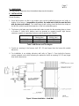
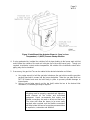
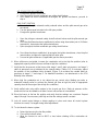
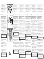
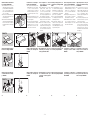
4. For installation in an existing refractory wall, refer to Figure 1. From inside the furnace,
remove rammed, cast or brick refractory as required to furnish an opening 1/2" (13 mm) larger
than the tile dimensions.
Figure 1. Burner Installation – Hard Wall
Burner Model Approx. Burner
Net Wt. (lbs.) Approx. Tile
Net Wt. (lbs.)
WHI-140/240 200 310
WHI-160/260 200 440
Y8111
(NOT TO SCALE)

Page 8
WHI-9
5. Wrap the outside of the tile with one or more layers of ceramic fiber rated for a higher
temperature than the furnace. Secure ceramic fiber with tape to retain the fiber during
installation of the tile.
6. Mount the self-supporting burner tile/burner assembly to the furnace shell plate using 5/8" (16
mm) studs positioned as shown on in Section D. Place the tile mounting flange gasket over
the studs followed by the burner tile assembly. Secure with lock washers and hex nuts.
Air & Fuel Connections
1. The burner air inlet connection can be located in any orientation, this is most easily achieved
by simply installing the entire tile/burner assembly in the desired position without dis-
assembling the burner from the tile.
2. Connect the air line to the burner inlet flange, install a matching gasket to minimize air
leakage. For the WHI__40 a gasket and flange are provided.
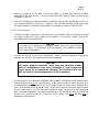
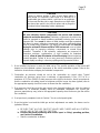
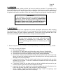
3. Provide power to the motorized Invisiflame valve actuator (see attached IC20 butterfly valve
actuator sheet) and verify the valve position is in the ‘open’ position as shown in Figure 2 for
low temperature furnace operation (< 1,600°F) of the burner, i.e. ‘firing’ mode. With the valve
open, air is allowed to flow to stages 1 and 2 of the burner, refer to the burner capacity tables
for the correct stage 1 and 2 air pressure in relation to stage 3 air pressure, check pressures
with a suitable manometer, and adjust the opening of the Invisiflame valve as required to
achieve the necessary pressure. Provide air to the burner and verify the flow prior to
attempting to light burners.
CAUTION
Be careful not to damage the Invisiflame control valve and actuator during
burner mounting. Do not attempt to lift the burner by the Invisiflame control
valve or associated piping.
CAUTION
The burner mounted Invisiflame control valve and motorized actuator
must be installed/wired in the correct orientation to insure proper/safe
burner startup for low temperature operation. The Invisiflame valve can
NOT be closed (0°) for low temperature (< 1,600°F) operation.

Page 9
WHI-9
Figure 2. Invisiflame Valve Actuator Shown in ‘Open’ or Low
Temperature (< 1,600°F) Furnace Startup Position
4. If using preheated air, insulate the outside of all air pipes leading to the burner main air inlet
and insulate the outside of the main air inlet pipe up to the main burner body. Though not
required, to minimize contact surface temperature, the outside of the Invisiflame control valve
piping may also be insulated.
5. If necessary, the gas inlet Tee can be rotated to the desired orientation as follows:
a. Use a pipe wrench to hold the gas tube in between the gas inlet tee and the gas tube
packing gland which screws into the burner backplate. Note the gas tube itself can
NOT be rotated and must be held firmly in place to prevent possible damage to
internal parts.
b. Using a second pipe wrench on the tee itself, rotate the tee to the desired inlet
orientation, re-seal with pipe dope if required.
IMPORTANT
All piping must be properly supported and aligned to
avoid stresses on the burner and associated
equipment. Hauck recommends that unions and
flexible connections be used on all air and fuel lines.
The unions will allow the burner to be more easily
serviced when required, and the flexible connections
will help isolate the burner from piping movement due
to expansion, contraction and vibration.
X8148
(NOT TO SCALE)

Page 10
WHI-9
6. Install and connect the gas line.
7. Install the spark igniter if applicable, down the center of the gas tee via the bushing provided.
Pipe ambient cooling air to the 1/2 NPT (DN 15) connection for continuous spark igniter
cooling flow. The cooling air connection should be supplied with minimum 20.9 "wc (5200 Pa)
of dry ambient purge air. If not using an ignition source, cooling air must be provided, at a
rate of approximately 1 cfm (0.027 nm3/m).
8. If applicable, install the pilot down the center of the gas tee via the bushing provided. Consult
the appropriate dimensional sheet and instructions that accompany the pilot for additional
information (ZMI-9).
9. If a UV scanner is used, install it in the correct accessory port located on the burner
backplate. Provide a minimum 20.9 "wc (5200 Pa) ambient dry air source for the UV scanner
air purge by connecting a cold air supply line to the 1/4 NPT (DN 6) bushing on the scanner
adapter using minimum 1/4" (6.3 mm) OD tubing or pipe and a suitable isolating valve.
10. Complete the mounting of pilot components and connection of air, gas, and air purge lines.
11. Inspect all bolted joints on the burner. Be sure all fasteners are tight.
F. IGNITION
WHI burners can be equipped with an air cooled spark igniter, IPE 50, or a Kromschroder ZMI
pilot. A 5000/6000 volt standard coil type ignition transformer can be utilized.
CAUTION
In order to ensure an adequate seal, it is important that the burner backplate
bolts be sufficiently tight. Before any attempt is made to start the burner,
check to ensure that the bolts are sufficiently tight and conduct a gas leak
test. Failure to check and ensure that a satisfactory seal exists by
conducting a leak test could result in the formation of a hazardous gas
leakage condition. Whenever burner internals are removed for cleaning or
replacement, be sure to tighten the backplate bolts and conduct a gas leak
test.
WARNING
Adjustment of this equipment, and its components, by unqualified
personnel, can result in fire, explosion, severe personal injury, or
even death.
NOTE
Manual ignition or torch lighting is not
recommended.

Page 11
WHI-9
For air cooled spark igniter set-up, perform the following:
1. Disconnect cooling air from spark igniter and remove spark igniter from burner.
2. Connect ignition wire to spark igniter electrode connection.
3. Energize the ignition transformer and verify that an adequate spark is produced between
the electrode tip and the outer tube.
4. De-energize ignition transformer.
5. If the spark is adequate, re-install spark igniter into burner. If the spark is weak or absent,
check integrity of spark wire insulators and possibility of short circuit behind electrode tip.
6. If spark is still absent, consult Hauck.
For gas pilot ignition see attached instructions.
G. INITIAL SETUP
WHI burners typically operate with automatic control systems. The burners are capable of
proportional control over their entire capacity range. In a typical system, ignition will be preceded
by a series of steps.
WARNING
When using a standard coil ignition transformer, provisions must
be made to eliminate the ignition spark falsely satisfying the
“flame on” UV scanner. Hauck designed flame supervisory panels
accomplish this by “timing out” the spark transformer after a short
(10 seconds for most applications) trial for ignition.
CAUTION
Initial adjustment and burner start-up should be
undertaken only by trained and experienced
personnel familiar with combustion systems,
control and safety circuitry and overall installation
procedures.
CAUTION
Ensure that all safety equipment and limits are
working properly before proceeding.
CAUTION
The ignition transformer can cause an electric shock. Use care
around the ignition cable. The igniter should be electrically
grounded and should NOT be handled while the transformer is
energized.

Page 12
WHI-9
1. Once installed, the burner is ready for initial set-up. The specific operation of the burner will
depend on the individual system components in the entire combustion system. Refer to the
instruction sheets that accompany the individual components.
2. Combustion air pressure should be set at the combustion air control valve. Typical
combustion air pressure range from a minimum of approximately 0.1"wc (25 Pa) to a
maximum of 22.5"wc (5600 Pa) static pressure at the inlet to the burner. Hauck recommends
that the combustion air setting remain at minimum until the burner has been ignited (refer to
the appropriate capacity sheet for burner air flow at low fire conditions).
3. Gas pressure should be set at the gas control valve (typically limiting gas valve for ambient
combustion air, or automatic butterfly valve for preheated combustion air). Actual gas
pressure required may vary (refer to the appropriate capacity sheet for burner gas flow at low
fire conditions).
4. If not previously completed, refer to Section F for air-cooled spark igniter.
5. Once the igniter is set and the initial gas and air adjustments are made, the burner can be
ignited as follows:
a. BE SURE THAT ALL FUEL SHUTOFF VALVES ARE CLOSED AND ALL CONTROL
VALVES ARE IN THE LOW FIRE POSITION.
b. Position the burner switching valve to the ‘open’ or ‘firing’ operating position,
see Section E Installation.
c. Start the combustion air blower.
CAUTION
Failure to achieve ignition of pilot or main flame within a
safe period (10 seconds) could result in a build-up of a
combustible gas mixture which could lead to an explosion.
In the event that the pilot or main flame does not light within
the above time period, shut off fuel valves and re-purge the
chamber before attempting further adjustment.
CAUTION
All cast refractory burner components are porous and therefore
subject to moisture absorption. Refractory components should not be
stored or exposed to damp conditions potentially reducing their normal
expected life. Care must be taken at initial startups and after extended
idle times to assure refractory components have been sufficiently dried
prior to normal firing conditions. It is highly recommended that low fire
drying for at least 6-8 hours at 50 to 100% excess air occur at initial
startups prior to exposing refractory components to normal firing
operation. Thereafter, if the refractory components are exposed to
excessive moisture, condensation, or high humidity for extended
periods, allow at least 30 minutes of low fire drying before beginning
normal operation. Failure to do so may cause any moisture present to
expand rapidly resulting in refractory spalling and/or premature failure.

Page 13
WHI-9
AIR-COOLED SPARK IGNITION
d. Energize the ignition transformer.
e. Open (energize) the main automatic gas safety shutoff valves.
f. Once flame has been established de-energize the ignition transformer, proceed to
step n.
GAS PILOT IGNITION
g. Ensure that the pilot automatic safety solenoid valves and the pilot manual gas valve
are closed.
h. Turn the pilot manual air valve to the full open position.
i. Energize the ignition transformer.
j. Open the pilot gas automatic safety shutoff solenoid valves and the pilot manual gas
valve.
k. Once the pilot flame has been established (confirm using observation port or UV flame
supervision), de-energize the ignition transformer.
l. Open (energize) the main automatic gas safety shutoff valves.
m. Once flame has been established, de-energize the ignition transformer, close the pilot
manual valve, and leave the manual pilot air valve open.
n. Proceed to ignite all burners (if applicable) per the above procedure.
6. When all burners are ignited, increase the combustion air to the high fire position (refer to
appropriate capacity sheet for burner air flow at high fire conditions).
7. Verify that the air pressure at the burner inlet, stage 1 and 2 static air pressure, and stage 3
static air pressures are as indicated in the capacity tables (Tables 1-4). If necessary, adjust
the position of the Invisiflame Valve Actuator (Figure 2) to achieve the needed static air
pressures at stage 1, 2 and stage 3. For detailed instructions, see attachment on the IC20
Butterfly Valve Actuator.
8. When high fire combustion air is set, adjust the gas control valve (limiting gas valve or
automatic butterfly valve) to achieve the desired gas flow at high fire (refer to appropriate
capacity sheet for burner gas flow at high fire conditions).
9. Verify air/fuel ratio using orifice meters in the air and gas lines. Static air pressure at the
burner air inlet can be related to air flows if an air orifice meter is not available.
10. Drive the burner to the low fire position and verify that the settings are consistent. Repeat
steps 6 through 9 as necessary until high and low fire settings remain constant.
11. Lock all control motor linkage or direct-couplings in place and return all control system
functions to normal, if changed during initial adjustments.
12. To shut down the burner system:
a. Return the burner to the low fire position.
b. Close all fuel shutoff valves.
c. Allow the furnace to cool to 800°F or less before shutting off the combustion air
blower.

Page 14
WHI-9
H. OPERATION
Once properly installed, ignited and fired, the burner is ready for operation. The operation of the
burner will depend on the specific items in the combustion control system and the application of
the burners. Refer to the instruction sheet that accompanies each item. The burner should always
be ignited under low fire conditions. When the burner is firing, the spark igniter should be shut off.
I. MAINTENANCE
Hauck WHI burners have been engineered to provide dependable performance while requiring
low maintenance. As with any product, it is very important to follow operating instructions and all
procedures carefully to obtain optimum performance. Please refer to the applicable WHI Parts
List to become familiar with the various burner components and assemblies.
1. Burner components which should be checked periodically and cleaned, if necessary, include:
Gas Body Assembly (All Models).
a. Disconnect the gas line.
b. Remove the IPE spark igniter or pilot from the center of burner (if applicable).
c. Remove the gas nozzle by screwing it counterclockwise from inside the furnace.
d. Remove the inner most set of eight hex nuts from the air body backplate.
e. Remove the outer most set of hex bolts holding the backplate to the main burner body
flange; pull away the backplate and gas tube assembly as one unit being careful not to
damage burner internal insulation.
f. Inspect internal parts. Clean the interior walls of gas body assembly and gas tube
assembly of any residue. Check the 4 radial holes located in the end of the gas tube
and clean if necessary.
g. If necessary, loosen the gas tube packing nut at the backplate and remove the gas
inlet tee to pull the gas tube out of the backplate assembly.
h. Inspect the four air holes located in the short pipe nipples attached to the plate on the
front of the gas tube, and clean of any residue or debri if necessary.
i. Check condition of internal refractory baffle and stage 1 and 2 air openings, semi
circles in refractory baffle, and clean if necessary.
IMPORTANT
If the refractory in the burner is exposed to excessive
moisture or extended periods of dampness, allow at least
30 minutes of low fire drying before beginning normal
operation. Failure to do so can cause moisture present
to expand rapidly, causing damage to the refractory.
CAUTION
Be sure burner internals have cooled sufficiently before
attempting to disassemble any components. Use care
when separating gasket surfaces to avoid damage to the
gaskets.

Page 15
WHI-9
j. Install a new burner backplate gasket if necessary, and reinsert gas tube and burner
backplate assembly. Ensure that the four stage 1 air holes located on the flat
plate attached to the end of the gas tube line up with the stage 1 air openings
(four innermost holes refractory baffle). The packing gland located on the rear of
the gas tube should be loosened slightly to ensure the gas tube assembly flat plate
located near the downstream end of the tube is firmly pressed into the back of the
burner refractory baffle, and also to rotate the gas tube slightly to correctly align the
stage 1 air holes (air holes in the gas tube plate match up to the air holes in the
refractory baffle). Retighten packing nut after correct alignment is attained and after
the burner backplate has already been securely tightened.
k. Reconnect the gas line.
Bypass Valve Seat (If applicable – WHI 260 Only).
a. Disconnect the bypass air valve from the bypass air line by removing the 4 bolts at the
bypass valve flanged connection.
b. Inspect the valve and valve seat, clean of any debris. Ensure that the valve disc
makes contact with the seat located in the valve body when in the ‘closed’ or
Invisiflame mode.
c. Install new fiberfrax gaskets between the valve body and flanges.
d. Tighten the 4 bolts with the valve centered in the bypass air line.
2. Replacement of Internal refractory Baffle
In certain situations, it may become necessary or desired to replace the internal baffle of the
burner. The baffle on the WHI burner is made of high temperature refractory. In order to
replace the internal baffle, use the following procedure:
a. Repeat step 1. a through e. above.
b. Pull the internal refractory baffle out through the burner internal air sleeve. To loosen
the baffle it may be necessary to push the baffle from inside the furnace.
c. Apply a thin layer (1/16 to 1/8”) of high temperature cement (Hauck recommends
Fiberfrax QF-150 or equivalent) to the baffle at each of the 3 rectangular shaped slots
and around the outside diameter of the baffle at the point of the angle change. Do not
put cement in or near the stage 2 air holes (semicircular shaped holes) of the baffle.
The cement will ensure a tight seal between the baffle and the cast alloy air sleeve
located in the front of the burner.
d. Slide the new baffle through the air tube being sure to align the 3 rectangular shaped
slots on the front side of the baffle with the 3 receiving tabs located on the burner
mounting flange. Be sure the baffle is properly aligned via the tabs and fully seats into
the locating tabs to insure a proper seal is made. Wipe any excess bonding cement
out of the stage 2 air holes if necessary.
e. Reinsert the burner gas tube assembly and burner backplate per step 1. j. above.
f. Reinstall all gas piping and check for gas leaks before restarting burner.
CAUTION
Failure to check and ensure that a satisfactory seal exists by
conducting a gas leak test could result in a hazardous condition.

Page 16
WHI-9
3. Replacement of Self-Supporting Refractory Tile
Refractory tiles should be checked for damage. Should it ever become necessary to replace
the burner refractory tile, use the following procedure:
a. Disconnect the main air and gas connections from the burner.
b. Remove flame scanning equipment and pilot or spark igniter from accessory ports to
prevent damage.
c. Support the burner weight before loosening burner mounting nuts.
d. Locate the burner to tile mounting nuts, the innermost nuts on the round tile or the 8
nuts located on a common bolt circle on the square tile version. Carefully support the
burner weight and remove the nuts and entire burner assembly.
e. Unbolt the tile mounting flange and remove the burner tile.
f. Remove the existing burner tile from the furnace wall and clean the tile port opening.
g. Inspect the refractory in the area surrounding the tile and repair any damage.
h. Replace the burner tile mounting gasket, if necessary.
i. Mount the new burner refractory tile per Section E ‘burner mounting’ steps 1 through 6
of these instructions.
j. Install a new burner mounting gasket and re-attach the burner assembly to the tile.
k. Reinstall air and gas lines and leak check per section E ‘air and fuel connections’
steps 2 through 11 of these Instructions.
J. RECOMMENDED SPARE PARTS LIST
Item Qty. Part Number Description
1 1 See Parts List Spark Igniter Assembly (If Applicable)
2 1 See Parts List UV Scanner
3 1 74105712 Actuator, Burner Switching Valve
Table 6. Recommended Spare Parts

- 1 -
D
GB
F
NL
I
E
D
GB
F
NL
I
E
D
GB
F
NL
I
E
D
GB
F
NL
I
E
D
GB
F
NL
I
E
D
GB
F
NL
I
E
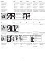
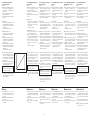
Ionisationszündbrenner
ZAI, ZMI, ZKIH
Betriebsanleitung
Bitte lesen und aufbewahren
Zeichenerklärung
, , , ... = Tätigkeit
= Hinweis
Alle in dieser Betriebsanleitung
aufgeführten Tätigkeiten dürfen
nur von autorisiertem Fach per-
sonal ausgeführt werden!
WARNING! Incorrect installation,
adjustment, modification, operation
or maintenance may cause injury or
material damage.
Read the instructions before use.
This unit must be installed in accord-
ance with the regulations in force.
Toutes les actions mentionnées
dans les présentes instructions
de service doivent être exécutées
par des spécialistes formés et au-
torisés uniquement !
ATTENTION ! Un montage, un ré-
glage, une modi fication, une utilisa-
tion ou un entretien in adaptés ris-
quent d’engendrer des dom mages
matériels ou corporels.
Lire les instructions avant utilisation.
Cet appareil doit être installé en res-
pectant les règlements en vigueur.
Alle in deze bedrijfshandleiding
vermelde werkzaamheden mo-
gen alleen door technici worden
uitgevoerd!
WAARSCHUWING! Ondeskundi-
ge inbouw, instelling, wijziging,
bediening of onder houds werk zaam-
heden kunnen per soonlijk letsel of
materiële schade veroor zaken.
Aanwijzingen voor het gebruik lezen.
Dit apparaat moet overeenkom-
stig de geldende regels worden
geïnstalleerd.
Tutte le operazioni indicate nelle
presenti istruzioni d’uso devono
essere eseguite soltanto dal pre-
posto esperto autorizzato.
ATTENZIONE! Se montaggio,
re go lazione, modifica, utilizzo o
manu tenzione non vengono ese guiti
correttamente, possono veri ficarsi
infortuni o danni.
Si prega di leggere le istruzioni prima
di utilizzare il prodotto che dovrà ve-
nire installato in base alle normative
vigenti.
¡Todas las actividades indicadas
en estas Instrucciones de utiliza-
ción, sólo deben realizarse por
una persona formada y autorizada!
¡ADVERTENCIA! La instalación,
ajuste, modificación, manejo o man-
tenimiento incorrecto puede ocasio-
nar daños personales o mate riales.
Leer las instrucciones antes de usar.
Este dispositivo debe ser instalado
observando las normativas en vigor.
03250560 01.06 Fx/ivd
7.1.1.2 Edition 11.10
Elster GmbH
Postfach 28 09
D-49018 Osnabrück
Ionisatie-aansteek-
branders
ZAI, ZMI, ZKIH
Bedieningsvoorschrift
Lezen en goed bewaren a.u.b.
Legenda
, , , ... = werkzaamheden
= aanwijzing
Brûleurs d’allumage à
ionisation
ZAI, ZMI, ZKIH
Instructions de service
À lire attentivement et à
conserver
Légendes
, , , ... = action
= remarque
Ionization pilot
burners
ZAI, ZMI, ZKIH
Operating instructions
Please read and keep in a safe
place
Explanation of symbols
, , , ... = Action
= Instruction
All the work set out in these
operating instructions may only
be completed by authorized
trained personnel!
Bruciatori pilota
a ionizzazione
ZAI, ZMI, ZKIH
Istruzioni d’uso
Si prega di leggere e conser-
vare
Spiegazione dei simboli
, , , ... = Operazione
= Avvertenza
Quemadores de encen-
dido controlados por
io nización ZAI, ZMI,
ZKIH
Instrucciones de
utilización
Se ruega que las lean y conser-
ven
Explicación de símbolos
, , , ... = Actividad
= Indicación
WARNUNG! Unsachgemäßer
Ein bau, Einstellung, Verän de rung,
Be die nung oder War tung kann
Ver letzungen oder Sachschäden
verursachen.
Anleitung vor dem Gebrauch lesen.
Dieses Gerät muss nach den gelten-
den Vorschriften installiert werden.
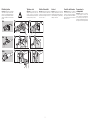
Inhaltsverzeichnis
Prüfen 2
Vorbereiten 3
Einbauen 4
Verdrahten 6
Dichtheit prüfen 7
In Betrieb nehmen 8
Wartung 9
Zubehör 10
Contents
Testing 2
Preparation 3
Installation 4
Wiring 6
Tightness test 7
Commissioning 8
Maintenance 9
Accessories 10
Sommaire
Vérifier 2
Préparation 3
Montage 4
Câblage 6
Vérifier l’étanchéité 7
Mise en service 8
Maintenance 9
Accessoires 10
Inhoudsopgave
Controleren 2
Voorbereiden 3
Inbouwen 4
Bedraden 6
Controle op lekkage 7
In bedrijf stellen 8
Onderhoud 9
Toebehoren 10
Indice
Verifica 2
Predisposizione 3
Montaggio 4
Cablaggio 6
Controllo della tenuta 7
Messa in servizio 8
Manutenzione 9
Accessori 10
Índice
Comprobar 2
Preparar 3
Montaje 4
Cableado 6
Comprobar la estanquidad 7
Puesta en funcionamiento 8
Mantenimiento 9
Accesorios 10

- 2 -
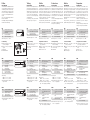
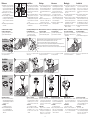
Prüfen
ZAI, ZMI, ZKIH
Ionisch überwachte Zündbrenner zum
sicheren Zünden von Gasbrennern in
Verbindung mit den Gasfeuerungs-
automaten BCU, IFS, IFD, PFD oder
PFS. Die Leistung des Zündbrenners
soll 2 bis 5 % des Hauptbrenners be-
tragen.
Auch als eigenständig betriebene
Brenner einsetzbar.
Für Erdgas, Stadtgas und Flüssiggas.
Andere Gase auf Anfrage.
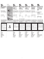
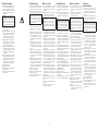
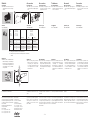
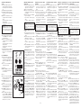
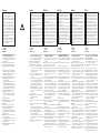
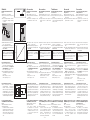
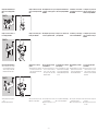
ZAI
ZAI Atmosphärischer Ionisa-
tionszündbrenner mit zwei
Elektroden
D-Osnabrück
Germany
84228010
ZAI R 3.03
R Rp-Innengewinde
TN NPT-Innengewinde
Leistung ca. 1,8 – 3 kW.
Lieferumfang
A Brenner mit Düse 1,3 mm
(0,051") für Erdgas
B Düse 0,7 mm (0,028") für Flüs-
siggas
C Kegelring
D Überwurfmutter
BD
C
A
ZMI
ZMI Ionisationszündbrenner mit
einer Elektrode D-49018 Osnabrück Germany
84230010
ZMI 16 B150R
Pmax. 1,5 kW
Gas N
.0535
16 – 25 Brennergröße
T T-Produkt
B
Gfür Erdgas
für Flüssiggas
150 – 600
Flammrohrlänge
R Rp-Innengewinde
N NPT-Innengewinde
Leistung:
ZMI 16: ca. 0,8 – 1,5 kW
ZMI 25: ca. 0,9 – 3,4 kW
Nennleistung P
max
, Gasart – siehe
Typenschild.
ZKIH
ZKIH Ionisationszündbrenner mit
zwangsweiser Luftzufuhr D-49018 Osnabrück Germany
84214010
ZKIH 150/100R
Pmax. 7 kW
Gas N, F, S
.0535
150 – 600
Brennerrohrlänge
/100 Flammrohrlänge
R Rp-Innengewinde
Nennleistung P
max
, Gasart – siehe
Typenschild.
Testing
ZAI, ZMI, ZKIH
Ionization-controlled pilot burners for
the safe ignition of gas burners in con-
junction with automatic burner control
units BCU, IFS, IFD, PFD or PFS. The
capacity of the pilot burner should be
2 to 5% of that of the main burner.
Can also be used as independently
operated burners.
For natural gas, town gas and LPG.
Other types of gas on request.
ZAI
ZAI
Thermo ionization pilot
burner with two electrodes
R Rp internal thread
TN NPT internal thread
Capacity approx. 1.8 – 3 kW.
Scope of delivery
A Burner with 1.3 mm (0.051")
nozzle for natural gas
B 0.7 mm (0.028") nozzle for LPG
C Cone olive
D Union nut
ZMI
ZMI
Ionization pilot burner with
one electrode
16 – 25 Burner size
T T-product
B
GFor natural gas
For LPG
150 – 600
Flame tube length
R Rp internal thread
N NPT internal thread
Capacity:
ZMI 16: approx. 0.8 – 1.5 kW.
ZMI 25: approx. 0.9 – 3.4 kW.
Rated capacity Pmax, gas type –
see type label.
ZKIH
ZKIH Ionization pilot burner with
forced air supply
150 – 600
Burner tube length
/100 Flame tube length
R Rp internal thread
Rated capacity Pmax, gas type –
see type label.
Vérifier
ZAI, ZMI, ZKIH
Brûleurs d’allumage à contrôle par
ionisation pour un allumage sûr des
brûleurs gaz en combinaison avec les
boîtiers de sécurité BCU, IFS, IFD,
PFD ou PFS. La puissance du brûleur
d’allumage doit être entre 2 et 5 %
de la puissance du brûleur principal.
Peuvent également être utilisés
comme brûleurs autonomes.
Pour gaz naturel, gaz de ville et GPL.
Autres types de gaz sur demande.
ZAI
ZAI
Brûleur pilote atmosphé-
rique à ionisation avec deux
électrodes
R Taraudage Rp
TN Taraudage NPT
Puissance env. 1,8 – 3 kW.
Programme de livraison
A Brûleur avec buse 1,3 mm (0,051")
pour gaz naturel
B Buse 0,7 mm (0,028") pour GPL
C Bague conique
D Écrou de raccord
ZMI
ZMI
Brûleur pilote à ionisation
avec une électrode
16 – 25 Taille du brûleur
T Produit T
B
GPour gaz naturel
Pour GPL
150 – 600
Longueur du tube de
flamme
R Taraudage Rp
N Taraudage NPT
Puissance :
ZMI 16 : env. 0,8 – 1,5 kW
ZMI 25 : env. 0,9 – 3,4 kW
Puissance nominale P
max
, type de
gaz – voir la plaque signalétique.
ZKIH
ZKIH Brûleur pilote à ionisation
avec alimentation en air
forcée
150 – 600
Longueur du tube de
flamme
/100 Longueur du tube de
flamme
R Taraudage Rp
Puissance nominale P
max
, type de
gaz – voir la plaque signalétique.
Controleren
ZAI, ZMI, ZKIH
Aansteekbranders met ionisatiebe-
waking voor het veilig ontsteken van
gasbranders in combinatie met de
branderautomaten BCU, IFS, IFD,
PFD of PFS. Het vermogen van de
aansteekbrander moet 2 tot 5% van
het vermogen van de hoofdbrander
bedragen.
Ook als zelfstandig gebruikte bran-
ders inzetbaar.
Voor aardgas, stadsgas en LPG. An-
dere gassen op aanvraag.
ZAI
ZAI
Atmosferische ionisatie-
aansteekbrander met twee
elektroden
R Binnendraad Rp
TN Binnendraad NPT
Vermogen: ca. 1,8 – 3 kW.
Leveringsomvang
A Brander met 1,3 mm (0,051") pijp-
stuk voor aardgas
B 0,7 mm (0,028") pijpstuk voor LPG
C Conische ring
D Wartelmoer
ZMI
ZMI
Ionisatie-aansteekbrander
met een elektrode
16 – 25 Brandergrootte
T T product
B
GVoor aardgas
Voor LPG
150 – 600
Lengte van de vlambuis
R Binnendraad Rp
N Binnendraad NPT
Vermogen:
ZMI 16: ca. 0,8 – 1,5 kW
ZMI 25: ca. 0,9 – 3,4 kW
Nominaal vermogen Pmax, gas-
soort – zie typeplaatje.
ZKIH
ZKIH Ionisatie-aansteekbrander
met geforceerde luchttoe-
voer
150 – 600
Lengte van de brander-
buis
/100 Lengte van de vlambuis
R Binnendraad Rp
Nominaal vermogen Pmax, gas-
soort – zie typeplaatje.
Verifica
ZAI, ZMI, ZKIH
Bruciatori pilota con controllo a io-
nizzazione per l’accensione sicura di
bruciatori a gas con apparecchiature
di controllo fiamma BCU, IFS, IFD,
PFD o PFS. La potenza del bruciatore
pilota deve essere tra il 2 e il 5 % del
bruciatore principale.
Utilizzabili anche come bruciatori
autonomi.
Per gas metano, gas di città e gas
liquido. Altri tipi di gas su richiesta.
ZAI
ZAI Bruciatore pilota atmosferi-
co a ionizzazione con due
elettrodi
R Filettatura femmina Rp
TN Filettatura femmina NPT
Potenza ca. 1,8 – 3 kW.
Corredo di fornitura
A Bruciatore con ugello 1,3 mm
(0,051") per metano
B Ugello 0,7 mm (0,028") per gas
liquido
C Giunto conico
D Dado ad ogiva
ZMI
ZMI
Bruciatore pilota a ionizza-
zione monoelettrodo
16 – 25 Dimensioni bruciatore
T Prodotto T
B
GPer metano
Per gas liquido
150 – 600
Lunghezza tubo guida-
fiamma
R Filettatura femmina Rp
N Filettatura femmina NPT
Potenza:
ZMI 16: ca. 0,8 – 1,5 kW
ZMI 25: ca. 0,9 – 3,4 kW
Portata nominale Pmax, tipo di
gas – vedi targhetta dati.
ZKIH
ZKIH Bruciatore pilota a ionizza-
zione ad aria soffiata
150 – 600
Lunghezza tubo bruciatore
/100 Lunghezza tubo guida-
fiamma
R Filettatura femmina Rp
Portata nominale Pmax, tipo di
gas – vedi targhetta dati.
Comprobar
ZAI, ZMI, ZKIH
Quemadores de encendido contro-
lados por ionización, para el encen-
dido seguro de quemadores de gas
en combinación con los controles de
quemador BCU, IFS, IFD, PFD o PFS.
La potencia del quemador de encen-
dido debe ser del 2 hasta el 5 % de
la del quemador principal.
También se pueden utilizar como
quemadores operados indepen-
dientemente.
Para gas natural, gas ciudad y GLP.
Otros tipos de gas bajo demanda.
ZAI
ZAI
Quemador atmosférico de
encendido por ionización
con dos electrodos
R Rosca interior Rp
TN Rosca interior NPT
Potencia aprox. 1,8 – 3 kW.
Componentes del suministro
A Quemador con tobera de 1,3 mm
(0,051") para gas natural
B Tobera de 0,7 mm (0,028") para
GLP
C Anillo cónico
D Tuerca de racor
ZMI
ZMI
Quemador de encendido
por ionización con un elec-
trodo
16 – 25 Tamaño del quemador
T Producto T
B
GPara gas natural
Para GLP
150 – 600
Longitud del tubo de llama
R Rosca interior Rp
N Rosca interior NPT
Potencia:
ZMI 16: aprox. 0,8 – 1,5 kW
ZMI 25: aprox. 0,9 – 3,4 kW
Potencia nominal Pmax, tipo de
gas – ver placa de características.
ZKIH
ZKIH Quemador de encendido
por ionización con alimen-
tación de aire forzada
150 – 600
Longitud del tubo del
quemador
/100 Longitud del tubo de
llama
R Rosca interior Rp
Potencia nominal Pmax, tipo de
gas – ver placa de características.

- 3 -
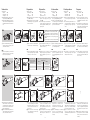
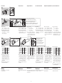
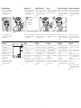
Vorbereiten
Gasarten:
Erdgas = N
Flüssiggas = F
Stadtgas = S
Alle Zündbrenner sind bei Liefe-
rung auf Erdgas N eingestellt.
Falls der Zündbrenner mit einer an-
deren Gasart als Erdgas betrieben
wird, Brenner für Gasart vorberei-
ten.
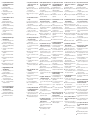
2
ZAI 34
0.7
7
65
B
B
Gasdüse ∅ 0,7 mm (0,028") für Flüssiggas.
Gas nozzle Ø 0.7 mm (0.028") for LPG.
Injecteur gaz Ø 0,7 mm (0,028") pour GPL.
Gaspijpstuk Ø 0,7 mm (0,028") voor LPG.
Ugello del gas Ø 0,7 mm (0,028") per gas
liquido.
Tobera de gas Ø 0,7 mm (0,028") para GLP.
Nach der Umstellung auf Flüssig-
gas die Luft neu einstellen (siehe
„In Betrieb nehmen“).
ZMI
Düsen-∅ prüfen, ob passend für
gewünschte Gasart. Passende
Düsen (siehe „Zubehör“).
2
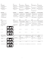
ZMI 3
Gasart/Gas type/
Type de gaz/Gas-
soort/Tipo di gas/
Tipo de gas
Düse/Nozzle/Buse/Pijpstuk/Ugello/Tobera
∅ [mm (inch)]
ZMI 16 ZMI 25
N0,94 (0,037) 1,40 (0,055)
F0,76 (0,029) 1,05 (0,041)
S1,30 (0,051) 1,78 (0,070)
2
ZKIH 3
IZ
45
+= N
+= F
= S
6789
Bei Betrieb mit Stadtgas S die
Halteschraube ohne den Düsen-
einsatz wieder einschrauben – den
Düseneinsatz nicht im Anschluss-
kasten aufbewahren.
Nach der Umstellung auf eine an-
dere Gasart die Luft neu einstellen
(siehe „In Betrieb nehmen“).
Voorbereiden
Gassoorten:
Aardgas = N
LPG = F
Stadsgas = S
Bij levering zijn alle aansteekbran-
ders op aardgas N ingesteld.
Indien de aansteekbrander met
een andere gassoort dan aardgas
wordt gebruikt, de brander op de
gassoort voorbereiden.
Na de omstelling op LPG de hoe-
veelheid lucht opnieuw instellen
(zie “In bedrijf stellen”).
ZMI
Pijpstukken-Ø controleren of dit
past voor de gewenste gassoort.
Passende pijpstukken (zie “Toebe-
horen”).
Bij gebruik met stadsgas S de
borgschroef er zonder het in-
zetstuk weer inschroeven – het
inzetstuk niet in de aansluitkast
bewaren.
Na de omstelling op een andere
gassoort de hoeveelheid lucht
opnieuw instellen (zie “In bedrijf
stellen”).
Préparation
Types de gaz :
Gaz naturel = N
GPL = F
Gaz de ville = S
À la livraison, tous les brûleurs
pilotes sont réglés pour le gaz
naturel N.
Si le brûleur pilote est utilisé avec
un autre type de gaz que du gaz
naturel, préparer le brûleur pour ce
type de gaz.
Après adaptation au GPL, procé-
der au réglage du débit d’air (voir
«Mise en service»).
ZMI
Vérifier que le Ø de la buse est
adapté au type de gaz souhaité.
Buses adéquates (voir « Acces-
soires »).
En cas d’emploi de gaz de ville S,
revisser la vis de fixation sans la
garniture de buse – ne pas conser-
ver la garniture de buse dans le
boîtier de jonction.
Après adaptation à un autre type
de gaz, procéder au réglage du
débit d’air (voir « Mise en ser-
vice»).
Preparation
Types of gas:
Natural gas = N
LPG = F
Town gas = S
All pilot burners are set for natural
gas N on delivery.
If the pilot burner is to be used with
a different type of gas, prepare the
burner for its use.
After conversion to LPG, adjust the
air volume (see “Commissioning”).
ZMI
Check if nozzle diameter is suitable
for the required gas type. Suitable
nozzles (see “Accessories”).
For operation with town gas S
screw the retaining screw back in
without the nozzle insert – do not
store the nozzle insert in the con-
nection box.
After conversion to another type
of gas, adjust the air volume (see
“Commissioning”).
Predisposizione
Tipi di gas:
Metano = N
Gas liquido = F
Gas di città = S
Alla consegna tutti i bruciatori pilo-
ta sono impostati su gas metano
N.
Se il bruciatore pilota funziona con
un tipo di gas diverso dal metano,
predisporlo per il tipo di gas spe-
cifico.
Dopo la conversione su gas liqui-
do, impostare di nuovo la quantità
di aria (vedi “Messa in servizio”).
ZMI
Controllare se il Ø dell’ugello è
adatto al tipo di gas scelto. Ugelli
adatti (vedi “Accessori”).
In caso di funzionamento con gas
di città S stringere di nuovo la vite
di fissaggio senza l’adattatore per
l’ugello – non conservare l’adatta-
tore nella scatola di raccordo.
Dopo la conversione su un altro
tipo di gas, impostare di nuovo
la quantità di aria (vedi “Messa in
servizio”).
Preparar
Tipos de gas:
Gas natural = N
GLP = F
Gas ciudad = S
Todos los quemadores de encen-
dido están ajustados para gas
natural N en el momento del su-
ministro.
Si el quemador de encendido tiene que
funcionar con un tipo de gas diferente
al gas natural, se deberá preparar el
quemador para ese tipo de gas.
Después de cambiar a GLP, ajus-
tar de nuevo la cantidad de aire
(ver “Puesta en funcionamiento”).
ZMI
Comprobar que el Ø de la tobera
es el adecuado para el tipo de gas
deseado. Toberas adecuadas (ver
“Accesorios”).
En caso de funcionar con gas ciu-
dad S, volver a atornillar el tornillo
de sujeción sin el suplemento de la
tobera – no guardar el suplemento
de la tobera en la caja de conexio-
nes.
Después de cambiar a otro tipo de
gas, ajustar de nuevo la cantidad
de aire (ver “Puesta en funciona-
miento”).

- 4 -
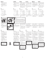
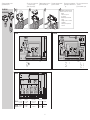
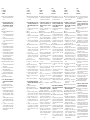
Einbauen
Zündbrenner so einbauen, dass
ein sicheres Zünden des Haupt-
brenners gewährleistet ist.
Wir empfehlen in die Gas- und
Luftzuleitung je einen Filter einzu-
bauen.
ZAI
Eingangsdruck:
Erdgas: 12 – 30 mbar
(4,8 – 12"WC),
Stadtgas: 6 – 20 mbar,
(2,4 – 8 "WC),
Flüssiggas: 30 – 50 mbar
(12 – 20 "WC).
Bei höherem Eingangsdruck Gas-
vordrossel einsetzen.
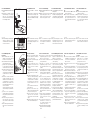
ZAI 1
Brenner an den zwei Löchern der Befestigungslasche
befestigen.
Attach the burner to the two holes on the fastening lug.
Fixer le brûleur au niveau des deux orifices de la patte de fixation.
De brander bevestigen aan de twee gaten van de bevestigingsstrip.
Fissare il bruciatore ai due fori della linguetta di fissaggio.
Fijar el quemador en los dos agujeros de la lengüeta de fijación.
Zündgasleitung mit 8×1 Kupferrohr
anschließen:
Beim Festschrauben der Über-
wurfmutter D auf die richtige Lage
des Kegelrings C achten – Kegel-
ring einfetten.
DC
≈ 2 mm
ZMI
Eingangsdruck:
Gas: 20 – 50 mbar (8 – 20 "WC),
Luft: 20 – 50 mbar (8 – 20 "WC).
Vor den Brenner Druckregler in die
Luft- und Gaszuleitung einbauen,
um den Luft- und Gasdruck ein-
stellen zu können.
Bei Betrieb mit Erdgas L, Stadtgas
und Flüssiggas sollte der einge-
stellte Luftdruck 20 – 30 % über
dem Gasdruck liegen.
Bei Betrieb mit anderen Gasarten
den Gasdruck entsprechend an-
passen.
ACHTUNG! Bei Einsatz als Zünd-
brenner müssen Gas- und Luftdruck
höher sein als die Anschlussdrücke
des Hauptbrenners.
Inbouwen
Aansteekbrander zo inbouwen
dat een veilige ontsteking van
de hoofdbrander gegarandeerd
wordt.
Wij raden u aan, in de gas- en
luchttoevoerleiding een filter in te
bouwen.
ZAI
Inlaatdruk:
Aardgas: 12 – 30 mbar,
(4,8 – 12"WC),
Stadsgas: 6 – 20 mbar,
(2,4 – 8 "WC),
LPG: 30 – 50 mbar
(12 – 20 "WC).
Bij hogere inlaatdrukken een gas-
restrictie-element voor de brander
inzetten.
De gasontstekingsleiding met 8×1
koperen buis aansluiten:
Bij het vastschroeven van de war-
telmoer D op de juiste positie van
de conische ring C letten – de co-
nische ring invetten.
ZMI
Inlaatdruk:
Gas: 20 – 50 mbar (8 – 20 "WC),
Lucht: 20 – 50 mbar (8 – 20 "WC).
Voor de brander drukregelaars in
de lucht- en gastoevoerleiding in-
bouwen om de lucht- en gasdruk
te kunnen instellen.
Bij gebruik met aardgas L, stads-
gas en LPG moet de ingestelde
luchtdruk 20 – 30% boven de
gasdruk liggen.
Bij gebruik met andere gassoorten
de gasdruk evenredig aanpassen.
ATTENTIE! Bij toepassing als aan-
steekbrander moeten de gas- en
luchtdruk hoger zijn dan de aan-
sluitdrukken van de hoofdbrander.
Montage
Procéder au montage du brûleur
pilote de façon à garantir un allu-
mage sûr du brûleur principal.
Nous recommandons l’installa-
tion d’un filtre dans la conduite
d’alimentation en gaz et dans la
conduite d’alimentation en air.
ZAI
Pression amont :
Gaz naturel : 12 – 30 mbar
(4,8 – 12 pouces CE),
Gaz de ville : 6 – 20 mbar
(2,4 – 8
pouces CE
),
GPL : 30 – 50 mbar
(12 – 20
pouces CE
).
En cas de pression amont plus éle-
vée, installer un obturateur primaire
de gaz.
Raccorder la conduite de gaz d’al-
lumage à l’aide d’un tube en cuivre
8×1 :
Lors du vissage de l’écrou de
raccord D, veiller à positionner
correctement la bague conique
C – graisser la bague conique.
ZMI
Pression amont :
Gaz : 20 – 50 mbar
(8 – 20 pouces CE),
Air : 20 – 50 mbar
(8 – 20 pouces CE).
Installer des régulateurs de pres-
sion dans les conduites d’alimen-
tation en gaz et air en amont du
brûleur afin de pouvoir régler la
pression d’air et de gaz.
En cas d’emploi de gaz naturel
L, de gaz de ville et de GPL, la
pression d’air réglée doit se situer
entre 20 et 30 % au-dessus de la
pression de gaz.
En cas d’emploi d’autres types de
gaz, adapter la pression de gaz en
conséquence.
ATTENTION ! En cas d’utilisation
comme brûleur pilote, les pres-
sions de gaz et d’air doivent être
plus élevées que les pressions de
raccordement du brûleur principal.
Installation
Install the pilot burner so that reli-
able ignition of the main burner is
guaranteed.
We recommend that a filter be
installed in the gas and air supply
line respectively.
ZAI
Inlet pressure:
Natural gas: 12 – 30 mbar
(4.8 – 12"WC),
Town gas: 6 – 20 mbar,
(2.4 – 8 "WC),
LPG: 30 – 50 mbar
(12 – 20 "WC).
In the case of higher inlet pres-
sures, insert a gas restrictor orifice.
Connect the pilot gas line with 8×1
copper tube:
When tightening union nut D, en-
sure that cone olive C is correctly
positioned – lubricate the cone
olive.
ZMI
Inlet pressure:
Gas: 20 – 50 mbar (8 – 20 "WC),
Air: 20 – 50 mbar (8 – 20 "WC).
Install pressure regulators in the
air and gas supply lines upstream
the burner so that the air and gas
pressures can be adjusted.
For operation with natural gas L,
town gas and LPG, the set air
pressure should be 20 – 30%
higher than the gas pressure.
For operation with other types of
gas, adjust the gas pressure cor-
respondingly.
IMPORTANT! If used as pilot burn-
er, the gas and air pressure must be
higher that the connection pressures
of the main burner.
Montaje
Montar el quemador de encendido
de manera que esté garantizado el
encendido seguro del quemador
principal.
Recomendamos instalar un filtro
en cada una de las líneas de ali-
mentación de gas y de aire.
ZAI
Presión de entrada:
Gas natural: 12 – 30 mbar
(4,8 – 12pulg. CA),
Gas ciudad: 6 – 20 mbar
(2,4 – 8 pulg. CA),
GLP: 30 – 50 mbar
(12 – 20 pulg. CA).
En caso de presión de entrada
más elevada, utilizar una estran-
gulación previa para gas.
Conectar la tubería de gas de en-
cendido con tubo de cobre 8×1:
Al apretar la tuerca de racor D
prestar atención a la correcta posi-
ción del anillo cónico C – engrasar
el anillo cónico.
ZMI
Presión de entrada:
Gas: 20 – 50 mbar (8 – 20 pulg. CA),
Aire: 20 – 50 mbar (8 – 20 pulg. CA).
Instalar reguladores de presión en
las líneas de alimentación de aire y
de gas, aguas arriba del quema-
dor, para poder ajustar la presión
del aire y del gas.
Si se opera con gas natural L, gas
ciudad o GLP, la presión de aire
ajustada deberá ser 20 – 30 %
mayor que la presión del gas.
Si se opera con otros tipos de ga-
ses, se deberá ajustar correspon-
dientemente la presión del gas.
¡ATENCIÓN! Cuando se utilice
como quemador de encendido, las
presiones del gas y del aire deben
ser mayores que las presiones de
conexión del quemador principal.
Montaggio
Montare il bruciatore pilota in mo-
do da garantire un’accensione
sicura del bruciatore principale.
Si consiglia di installare un filtro
sia nella conduttura del gas che
in quella dell’aria.
ZAI
Pressione di entrata:
metano: 12 – 30 mbar,
(4,8 – 12"WC),
gas di città: 6 – 20 mbar,
(2,4 – 8 "WC),
gas liquido: 30 – 50 mbar
(12 – 20 "WC).
In caso di pressione di entrata
elevata inserire un regolatore di
portata gas in entrata.
Collegare la conduttura del gas
pilota con tubo in rame 8×1:
Nel serrare il dado ad ogiva D,
prestare attenzione al corretto
posizionamento del giunto conico
C – ingrassare il giunto conico.
ZMI
Pressione di entrata:
gas: 20 – 50 mbar (8 – 20 "WC),
aria: 20 – 50 mbar (8 – 20 "WC).
Montare degli stabilizzatori di pres-
sione nella conduttura dell’aria e
del gas, a monte del bruciatore,
per poter regolare la pressione
dell’aria e del gas.
In caso di funzionamento con me-
tano L, gas di città e gas liquido,
la pressione dell’aria impostata
dovrebbe essere superiore del
20 – 30 % rispetto alla pressione
del gas.
In caso di funzionamento con altri
tipi di gas adeguare, di conse-
guenza, la pressione del gas.
ATTENZIONE! In caso di utilizzo
come bruciatore pilota, la pressione
del gas e dell’aria devono essere su-
periori alle pressioni di collegamento
del bruciatore principale.
La page charge ...
La page charge ...
La page charge ...
La page charge ...
La page charge ...
La page charge ...
La page charge ...
La page charge ...
La page charge ...
La page charge ...
La page charge ...
La page charge ...
La page charge ...
La page charge ...
La page charge ...
La page charge ...
La page charge ...
La page charge ...
La page charge ...
La page charge ...
La page charge ...
La page charge ...
La page charge ...
La page charge ...
La page charge ...
La page charge ...
La page charge ...
La page charge ...
La page charge ...
La page charge ...
-
 1
1
-
 2
2
-
 3
3
-
 4
4
-
 5
5
-
 6
6
-
 7
7
-
 8
8
-
 9
9
-
 10
10
-
 11
11
-
 12
12
-
 13
13
-
 14
14
-
 15
15
-
 16
16
-
 17
17
-
 18
18
-
 19
19
-
 20
20
-
 21
21
-
 22
22
-
 23
23
-
 24
24
-
 25
25
-
 26
26
-
 27
27
-
 28
28
-
 29
29
-
 30
30
-
 31
31
-
 32
32
-
 33
33
-
 34
34
-
 35
35
-
 36
36
-
 37
37
-
 38
38
-
 39
39
-
 40
40
-
 41
41
-
 42
42
-
 43
43
-
 44
44
-
 45
45
-
 46
46
-
 47
47
-
 48
48
-
 49
49
-
 50
50


dans d''autres langues
- italiano: Hauck WHI Istruzioni per l'uso
- English: Hauck WHI Operating instructions
- español: Hauck WHI Instrucciones de operación
- Nederlands: Hauck WHI Handleiding