
MODEL Variable speed
CORDLESS IMPACT WRENCH
MODÈLE
CLÉ À CHOC À BATTERIE
MODELO
LLAVE DE IMPACTO A BATERÍA
WR 12DM
•
WR 9DM
INSTRUCTIONS DE SECURITE ET MODE D’EMPLOI
AVERTISSEMENT
Une utilisation INCORRECTE OU DANGEREUSE de cet outil motorisé peut entraîner
la mort ou de sérieuses blessures corporelles!
Ce mode d’emploi contient d’importantes informations à propos de la sécurité de
ce produit. Prière de lire et de comprendre ce mode d’emploi AVANT d’utiliser
l’outil motorisé. Garder ce mode d’emploi à la disponibilité des autres utilisateurs
et propriétaires avant qu’ils utilisent l’outil motorisé. Ce mode d’emploi doit être
conservé dans un endroit sûr.
SAFETY INSTRUCTIONS AND INSTRUCTION MANUAL
WARNING
IMPROPER OR UNSAFE use of this power tool can result in death or serious bodily
injury!
This manual contains important information about product safety. Please read
and understand this manual BEFORE operating the power tool. Please keep this
manual available for other users and owners before they use the power tool. This
manual should be stored in safe place.
INSTRUCCIONES DE SEGURIDAD Y MANUAL DE INSTRUCCIONES
ADVERTENCIA
¡La utilización INAPROPIADA O PELIGROSA de esta herramienta eléctrica puede
resultar en lesiones de gravedad o la muerte!
Este manual contiene información importante sobre la seguridad del producto.
Lea y comprenda este manual ANTES de utilizar la herramienta eléctrica. Guarde
este manual para que puedan leerlo otras personas antes de utilizar la herramienta
eléctrica. Este manual debe ser guardado en un lugar seguro.

CONTENTS
English
Page
IMPORTANT SAFETY INFORMATION ............... 3
MEANINGS OF SIGNAL WORDS....................... 3
SAFETY .................................................................... 4
GENERAL SAFETY RULES – FOR ALL
BATTERY OPERATED TOOLS ..................... 4
SPECIFIC SAFETY RULES ................................... 6
IMPORTANT SAFETY INSTRUCTIONS FOR
USE OF THE CORDLESS IMPACT WRENCH ....
7
IMPORTANT SAFETY INSTRUCTIONS
FOR BATTERY CHARGER............................ 7
IMPORTANT SAFETY INSTRUCTIONS
FOR USE OF THE BATTERY AND
BATTERY CHARGER .................................... 9
FUNCTIONAL DESCRIPTION ................................ 10
MODEL ............................................................... 10
NAME OF PARTS .............................................. 10
TABLE DES MATIERES
ÍNDICE
Página
ESPECIFICACIONES ............................................ 67
MONTAJE Y OPERACIÓN....................................... 68
APLICACIONES ................................................... 68
MÉTODO DE EXTRACCIÓN E INSTALACIÓN
DE LA BATERÍA ............................................ 68
MÉTODO DE CARGA .......................................... 68
ANTES DE LA UTILIZACIÓN .............................. 71
OPERACIÓN ......................................................... 71
PRECAUCIONES OPERACIONALES .................. 73
MANTENIMIENTO E INSPECCIÓN ........................ 78
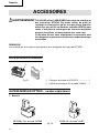
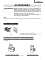
ACCESORIOS ........................................................... 81
ACCESORIOS ESTÁNDAR.................................. 81
ACCESORIOS OPCIONALES .............................. 81
Page
SPECIFICATIONS .............................................. 11
ASSEMBLY AND OPERATION ............................. 12
APPLICATIONS.................................................. 12
REMOVAL AND INSTALLATION METHOD
OF BATTERY .................................................. 12
CHARGING METHOD........................................ 12
BEFORE USE ..................................................... 15
OPERATION ....................................................... 15
OPERATIONAL CAUTIONS .............................. 16
MAINTENANCE AND INSPECTION ..................... 21
ACCESSORIES ....................................................... 23
STANDARD ACCESSORIES ............................. 23
OPTIONAL ACCESSORIES ............................... 23
Page
INFORMATIONS IMPORTANTES DE SÉCURITÉ
.. 29
SIGNIFICATION DES MOTS D’AVERTISSEMEN
T .... 29
SECURITE ................................................................ 30
REGLES GENERALE DE SECURITE – POUR TOUS
LES OUTILS FONCTIONNANT SUR BATTERIE ...
30
REGLES DE SECURITE SPECIFIQUES ............... 32
CONSIGNES DE SÉCURITÉ IMPORTANTES POUR
L'UTILISATION DU CLÉ À CHOC À BATTERIE
.....
33
CONSIGNES DE SÉCURITÉ IMPORTANTES
POUR L’UTILISATION DU CHARGEUR DE BATTERIE ...
34
CONSIGNES DE SÉCURITÉ IMPORTANTES POUR L’UTILISATION
DE LA BATTERIE ET DU CHARGEUR DE BATTERIE ...............
35
DESCRIPTION FONCTIONNELLE ........................... 37
MODELE ............................................................... 37
NOM DES PARTIES............................................. 37
Page
SPECIFICATIONS ................................................ 38
ASSEMBLAGE ET FONCTIONNEMENT ..........................
39
UTILISATIONS ..................................................... 39
MÉTHODE DE RETRAIT ET D’INSTALLATION
DE LA BATTERIE .......................................... 39
MÉTHODE DE RECHARGE ................................. 39
AVANT L’UTILISATION ...................................... 42
UTILISATION ....................................................... 42
PRÉCAUTIONS D'UTILISATION......................... 45
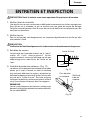
ENTRETIEN ET INSPECTION .................................. 49
ACCESOIRES ........................................................... 52
ACCESSOIRES STANDARD ............................... 52
ACCESSOIRES EN OPTION ................................ 52
Français
Español
Página
INFORMACIÓN IMPORTANTE SOBRE SEGURIDAD
.... 58
SIGNIFICADO DE LAS PALABRAS DE SEÑALIZACIÓN
.. 58
SEGURIDAD ............................................................. 59
NORMAS GENERALES DE SEGURIDAD – PARA TODAS
LAS HERRAMIENTAS ALIMENTADAS CON BATERÍA
.. 59
NORMAS ESPECÍFICOS DE SEGURIDAD ......... 61
INSTRUCCIONES IMPORTANTES PARA LA UTILIZACIÓN
DEL LLAVE DE IMPACTO A BATERÍA ..........................
62
INSTRUCCIONES IMPORTANTES DE SEGURIDAD
PARA EL CARGADOR DE BATERÍAS
................. 63
INSTRUCCIONES IMPORTANTES DE SEGURIDAD
PARA LA BATERÍA Y EL CARGADOR DE BATERÍAS
... 64
DESCRIPCIÓN FUNCIONAL .................................... 66
MODELO .............................................................. 66
NOMENCLATURA ............................................... 66

English
3
IMPORTANT SAFETY INFORMATION
Read and understand all of the safety precautions, warnings and operating instructions in
the Instruction Manual before operating or maintaining this power tool.
Most accidents that result from power tool operation and maintenance are caused by the
failure to observe basic safety rules or precautions. An accident can often be avoided by
recognizing a potentially hazardous situation before it occurs, and by observing appropriate
safety procedures.
Basic safety precautions are outlined in the “SAFETY” section of this Instruction Manual and
in the sections which contain the operation and maintenance instructions.
Hazards that must be avoided to prevent bodily injury or machine damage are identified by
WARNINGS on the power tool and in this Instruction Manual.
NEVER use this power tool in a manner that has not been specifically recommended by
HITACHI.
MEANINGS OF SIGNAL WORDS
WARNING indicates a potentially hazardous situations which, if ignored, could result in
death or serious injury.
CAUTION indicates a potentially hazardous situations which, if not avoided, may result in
minor or moderate injury, or may cause machine damage.
NOTE emphasizes essential information.

English
4
SAFETY
GENERAL SAFETY RULES – FOR ALL BATTERY OPERATED TOOLS
WARNING: Read and understand all instructions.
Failure to follow all instructions listed below, may result in electric shock,
fire and/or serious personal injury.
SAVE THESE INSTRUCTIONS
1. Work Area
(1) Keep your work area clean and well lit. Cluttered benches and dark areas invite
accidents.
(2) Do not operate power tools in explosive atmospheres, such as in the presence of
flammable liquids, gases, or dust. Power tools create sparks which may ignite the
dust of fumes.
(3) Keep bystanders children, and visitors away while operating a power tool.
Distractions can cause you to lose control.
2. Electrical Safety
(1) A battery operated tool with integral batteries or a separate battery pack must be
recharged only with the specified charger for the battery.
A charger that may be suitable for one type of battery may create a risk of fire when
used with another battery.
(2) Use battery operated tool only with specifically designed battery pack.
Use of any other batteries may create a risk of fire.
3. Personal Safety
(1) Stay alert, watch what you are doing and use common sense when operating a
power tool. Do not use tool while tired or under the influence of drugs, alcohol, or
medication. A moment of inattention while operating power tools may result in
serious personal injury.
(2) Dress properly. Do not wear loose clothing or jewelry. Contain long hair. Keep your
hair, clothing and gloves away from moving parts. Loose clothes, jewelry, or long hair
can be caught in moving parts.
(3) Avoid accidental starting. Be sure switch is off position before inserting battery.
Carrying tools with your finger on the switch or inserting the battery pack into a tool
with the switch on invites accidents.
(4) Remove adjusting keys or wrenches before turning the tool on. A wrench or a key that
is left attached to a rotating part of the tool may result in personal injury.
(5) Do not overreach. Keep proper footing and balance at all times. Proper footing and
balance enable better control of the tool in unexpected situations.
(6) Use safety equipment. Always wear eye protection. Dust mask, non-skid safety
shoes, hard hat, or hearing protection must be used for appropriate conditions.

English
5
4. Tool Use and Care
(1) Use clamps or other practical way to secure and support the workpiece to a stable
platform. Holding the work by hand or against your body is unstable and may lead to
loss of control.
(2) Do not force tool. Use the correct tool for your application. The correct tool will do
the job better and safer at the rate for which it is designed.
(3) Do not use tool if switch does not turn it on or off. Any tool that cannot be controlled
with the switch is dangerous and must be repaired.
(4) Disconnect battery pack from tool or place the switch in the locked or off position
before making any adjustments, changing accessories, or storing the tools. Such
preventive safety measures reduce the risk of starting the tool accidentally.
(5) Store idle tools out of reach of children and other untrained persons. Tools are
dangerous in the hands of untrained users.
(6) When battery pack is not in use, keep it away from other metal objects like: paper
clips, coins, keys, nails, screws, or other small metal objects that can make a
connection from one terminal to another.
Shorting the battery terminals together may cause sparks, burns, or a fire.
(7) Maintain tools with care. Keep cutting tools sharp and clean. Properly maintained
tools, with sharp cutting edges are less likely to bind and are easier to control.
(8) Check for misalignment or binding of moving parts, breakage of parts, and any other
condition that may affect the tools operation. If damaged, have the tool serviced
before using. Many accidents are caused by poorly maintained tools.
(9) Use only accessories that are recommended by the manufacturer for your model.
Accessories that may be suitable for one tool, may become hazardous when used on
another tool.
5. Service
(1) Tool service must be performed only by qualified repair personnel. Service or
maintenance performed by unqualified personnel could result in a risk of injury.
(2) When servicing a tool, use only identical replacement parts. Follow instructions in
the Maintenance section of this manual. Use of unauthorized parts or failure to follow
Maintenance Instruction may create a risk of electric shock or injury.
WARNING:
Some dust created by power sanding, sawing, grinding, drilling, and other construc-
tion activities contains chemicals known to the State of California to cause cancer,
birth defects or other reproductive harm. Some examples of these chemicals are:
● Lead from lead-based paints,
● Crystalline silica from bricks and cement and other masonry products, and
● Arsenic and chromium from chemically-treated lumber.
Your risk from these exposures varies, depending on how often you do this type
of work. To reduce your exposure to these chemicals: work in a well ventilated area,
and work with approved safety equipment, such as those dust masks that are specially
designed to filter out microscopic particles.

English
6
SPECIFIC SAFETY RULES
1. Hold tools by insulated gripping surfaces when performing an operation where the
cutting tool may contact hidden wiring. Contact with a “live” wire will make exposed
metal parts of the tool “live” and shock the operator.
2. Never touch moving parts.
Never place your hands, fingers or other body parts near the tool’s moving parts.
3. Never operate without all guards in place.
Never operate this tool without all guards or safety features in place and in proper
working order. If maintenance or servicing requires the removal of a guard or safety
feature, be sure to replace the guard or safety feature before resuming operation of the
tool.
4. Use right tool.
Don’t force small tool or attachment to do the job of a heavy-duty tool.
Don’t use tool for purpose not intended —for example— don’t use circular saw for cutting
tree limbs or logs.
5. Never use a power tool for applications other than those specified.
Never use a power tool for applications other than those specified in the Instruction
Manual.
6. Handle tool correctly.
Operate the tool according to the instructions provided herein. Do not drop or throw the
tool. Never allow the tool to be operated by children, individuals unfamiliar with its
operation or unauthorized personnel.
7. Definitions for symbols
V .... volts
---
— ............. direct current
n
o
............ no load speed
---/min ..... revolutions or reciprocation per minute
8. Keep all screws, bolts and covers tightly in place.
Keep all screws, bolts, and plates tightly mounted. Check their condition periodically.
9. Do not use power tools if the plastic housing or handle is cracked.
Cracks in the tool’s housing or handle can lead to electric shock. Such tools should not
be used until repaired.
10. Blades and accessories must be securely mounted to the tool.
Prevent potential injuries to youself or others. Blades, cutting implements and accesso-
ries which have been mounted to the tool should be secure and tight.
11. Never use a tool which is defective or operating abnormally.
If the tool appears to be operating unusually, making strange noises, or otherwise
appears defective, stop using it immediately and arrange for repairs by a Hitachi
authorized service center.
12. Carefully handle power tools.
Should a power tool be dropped or struck against hard materials inadvertently, it may be
deformed, cracked, or damaged.
13. Do not wipe plastic parts with solvent.
Solvents such as gasoline, thinner benzine, carbon tetrachloride, and alcohol may
damage and crack plastic parts. Do not wipe them with such solvents.
Wipe plastic parts with a soft cloth lightly dampened with soapy water and dry
thoroughly.

English
7
IMPORTANT SAFETY INSTRUCTIONS FOR USE OF THE
CORDLESS IMPACT WRENCH
WARNING: Death or serious bodily injury could result from improper or unsafe use
of the cordless impact wrench. To avoid these risks, follow these basic
safety instructions:
1. Never use this wrench handle for any application other than those in this manual.
2. When working in high places, always make sure that there is no one below before starting
to work.
3. Always wear eye and ear protection when you work.
4. Confirm whether the socket has any crack in it.
5. Attach the hex. socket securely onto the anvil. If the hex. socket is insufficiently secured,
it may drop out and cause an accident. For hex. socket attachment refer to “OPERATION”
on page 15.
6. Confirm the tightening torque by a torque wrenck before use in order to ascertain the
correct tightening torque to be used.
7. If a universal joint is used, be sure not to operate the unit in a no-load condition. Operatig
in this condition is dangerous. When the socket section spins around it may cause injury
to hands or bodies, or the resuluting intense vibration may cause the user to drop the tool.
8. Be careful that foreign matters do not block the holes located on both sides of the handle.
Also do not close the holes with a tape. The holes act an important role.
IMPORTANT SAFETY INSTRUCTIONS
FOR BATTERY CHARGER
1. This manual contains important safety and operating instructions for battery charger
Model UC14YF2.
2. Before using battery charger, read all instructions and cautionary markings on (1) battery
charger, (2) battery, and (3) product using battery.
3. To reduce risk of injury, charge HITACHI rechargeable battery type EB7, EB9, EB12, EB14
series. Other type of batteries may burst causing personal injury and damage.
4. Do not expose battery charger to rain or snow.
5. Use of an attachment not recommended or sold by the battery charger manufacturer may
result in a risk of fire, electric shock, or injury to persons.
6. To reduce risk of damage to electric plug and cord, pull by plug when disconnecting
battery charger.
7. Make sure cord is located so that it will not be stepped on, tripped over, or otherwise
subjected to damage or stress.
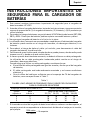
8. An extension cord should not be used unless absolutely necessary. Use of improper
extension cord could result in a risk of fire and electric shock.
If extension cord must be used make sure:

English
8
a. That blades of extension cord are the same number, size, and shape as those of plug
on battery charger:
b. That extension cord is properly wired and in good electrical condition; and
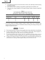
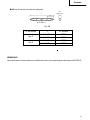
c. That wire size is large enough for AC ampere rating of battery charger as specified
in Table 1.
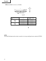
* If the input rating of a battery charger is given in watts rather than in amperes, the
corresponding ampere rating is to be determined by dividing the wattage rating by the
voltage rating–for example:
9. Do not operate battery charger with damaged cord or plug-replace them immediately.
10. Do not operate battery charger if it has received a sharp blow, been dropped, or
otherwise damaged in any way; take it to a qualified serviceman.
11. Do not disassemble battery charger; take it to a qualified serviceman when service or
repair is required. Incorrect reassembly may result in a risk of electric shock or fire.
12. To reduce risk of electric shock, unplug charger from receptacle before attempting any
maintenance or cleaning. Removing the battery will not reduce this risk.
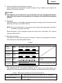
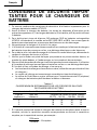
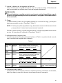
Table 1
RECOMMENDED MINIMUM AWG SIZE FOR
EXTENSION CORDS FOR BATTERY CHARGERS
AC Input Rating Amperes* AWG Size of Cord
Equal to or but less Length of Cord, Feet (Meter)
greater than than 25 (7.5) 50 (15) 100 (30) 150 (45)
0 2 18 18 18 16
2 3 18 18 16 14
3 4 18 18 16 14
1250watts
125 volts
= 10 amperes

English
9
IMPORTANT SAFETY INSTRUCTIONS FOR USE OF THE
BATTERY AND BATTERY CHARGER
You must charge the battery before you can use the cordless impact wrench. Before using
the model UC14YF2 battery charger, be sure to read all instructions and cautionary
statements on it, the battery and in this manual.
REMEMBER: USE ONLY HITACHI BATTERY TYPES EB7 SERIES, EB9 SERIES, EB12 SERIES,
EB14 SERIES. OTHER TYPES OF BATTERIES MAY BURST AND CAUSE INJURY!
Follow these instructions to avoid the risk of injury:
WARNING: Improper use of the battery or battery charger can lead to serious injury.
To avoid these injuries:
1. NEVER disassemble the battery.
2. NEVER incinerate the battery, even if it is damaged or is completely worn out. The
battery can explode in a fire.
3. NEVER short-circuit the battery.
4. NEVER insert any objects into the battery charger’s air vents. Electric shock or
damage to the battery charger may result.
5. NEVER charge outdoors. Keep the battery away from direct sunlight and use only
where there is low humidity and good ventilation.
6. NEVER charge when the temperature is below 32°F (0°C) or above 104°F (40°C).
7. NEVER connect two battery chargers together.
8. NEVER insert foreign objects into the hole for the battery or the battery charger.
9. NEVER use a booster transformer when charging.
10. NEVER use an engine generator or DC power to charge.
11. NEVER store the battery or battery charger in places where the temperature may
reach or exceed 104°F (40°C).
12. ALWAYS operate charger on standard household electrical power (120 volts). Using
the charger on any other voltage may overheat and damage the charger.
13. ALWAYS wait at least 15 minutes between charges to avoid overheating the charger.
14. ALWAYS disconnect the power cord from its receptacle when the charger is not in use.
SAVE THESE INSTRUCTIONS
AND
MAKE THEM AVAILABLE TO
OTHER USERS
AND
OWNERS OF THIS TOOL!

English
10
EB9BEB1220BL
MODEL
WR12DM: with charger (UC14YF2) and case
WR9DM: with charger (UC14YF2) and case
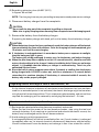
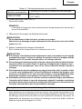
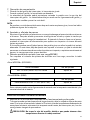
NAME OF PARTS
1. Cordless Impact Wrench
䡬 Battery
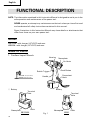
FUNCTIONAL DESCRIPTION
NOTE: The information contained in this Instruction Manual is designed to assist you in the
safe operation and maintenance of the power tool.
NEVER operate, or attempt any maintenance on the tool unless you have first read
and understood all safety instructions contained in this manual.
Some illustrations in this Instruction Manual may show details or attachments that
differ from those on your own power tool.
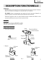
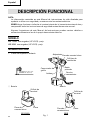
Fig. 1
Nameplate
Switch Trigger
Handle
Push Button
Housing
Air Vents
Convenient
Hook
Battery
Nameplate
Nameplate
Latch
Terminal
Hole
Latch
Terminal
Hole
WR12DM: 1/2" (12.7 mm)
WR9DM: 3/8" (9.5 mm)

English
11
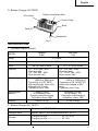
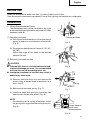
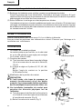
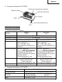
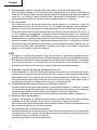
2. Battery Charger (UC14YF2)
SPECIFICATIONS
1. Cordless Impact Wrench
Input power source Single phase: AC120V, 60Hz
Charging time Approx. 60min. (At a temperature of 68°F (20°C))
Charger
Charging voltage .......................... DC 7.2–14.4V
Charging current........................... DC 1.9A
Weight 2.9 lbs (1.3kg)
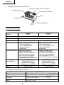
2. Battery Charger (UC 14YF2)
Fig. 2
Pilot Lamp
Cord
Battery Installation Hole
Caution Plate
Body
Nameplate
MODEL
WR9DM WR12DM
(9.6V) (12V)
Motor DC motor
No-load speed 0 – 2,300/min
Drive 3/8" (9.5 mm) square 1/2" (12.7 mm) square
Capacity 1/4" – 9/16" (M6 – M14) 1/4" – 5/8" (M6 – M16)
(Ordinary bolt) (Ordinary bolt)
1/4" – 3/8" (M6 – M10) 1/4" – 15/32" (M6 – M12)
(High tension bolt) (High tension bolt)
Tightening torque Maximum 780 in-lbs Maximum 1330 in-lbs
(88.2 N·m, 900 kgf·m) (150 N·m, 1530 kgf·m)
Tightening is 15/32" (M12) Tightening is 5/8" (M16) F10T,
high tension bolt, when fully when fully charged at 20°C
charged in 20°C temp. temp.
Tighttening time: 3 sec. Tightening time: 3 sec.
Rechargeable EB9B (2.0 Ah) EB1220BL (2.0 Ah)
battery Ni-Cd battery, 9.6V Ni-Cd battery, 12V
Charging and discharging Charging and discharging
Frequency: about 1000 Frequency: about 1000
Weight 3.0 lbs (1.4 kg) 3.5 lbs (1.6 kg)

English
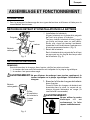
12
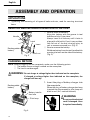
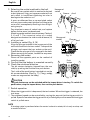
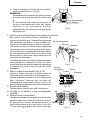
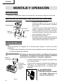
Handle
Insert
Latch
Rechargeable
battery
Fig. 3
Fig. 4
Pull out
ASSEMBLY AND OPERATION
APPLICATIONS
䡬 Tightening and loosening of all types of bolts and nuts, used for securing structural
items.
REMOVAL AND INSTALLATION METHOD OF BATTERY
䡬 How to install the battery.
Align the battery with the groove in tool
handle and slip it into place.
Always insert it all the way until it locks in
place with a little click, If not, it may acciden-
tally fall out of the tool, causing injury to
you or someone around you. (Fig. 3)
䡬 How to remove the battery.
Withdraw battery from the tool handle while
pressing the latch on the side of the battery.
(Fig. 3)
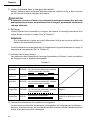
CHARGING METHOD
NOTE: Before plugging into the receptacle, make sure the following points.
䡬 The power source voltage is stated on the nameplate.
䡬 The cord is not damaged.
WARNING: Do not charge at voltage higher than indicated on the nameplate.
If charged at voltage higher than indicated on the nameplate, the
charger will burn up.
1. Insert the plug of battery charger into
the receptacle.
When the plug of battery charger has been
inserted into the receptacle, pilot lamp will
blink in red. (At 1-second intervals)
WARNING:
Do not use the electrical
cord if damaged. Have
it repaired immediately.
d
Battery installa-
tion hole
Pilot lamp
Rechargeable
battery

English
13
2. Insert the battery to the battery charger.
Insert the battery into the battery charger as shown in Fig. 4. Make sure it contacts the
bottom of the battery charger.
CAUTION:
● If the batteries are inserted in the reverse direction, not only recharging will become
impossible, but it may also cause problems in the charger such as a deformed recharging
terminal.
3. Charging
When the battery is connected to the battery charger, charging will commence and the
pilot lamp will light in red. (See Table 2)
NOTE: If the pilot lamp flikers in red, pull out the plug from the receptacle and check if
the battery is properly mounted.
When the battery is fully charged, the pilot lamp will blink in red slowly. (At 1-second
intervals) (See Table 2)
(1) Pilot lamp indication
The indications of the pilot lamp will be as shown in Table 2, according to the condition
of the charger or the rechargeable battery.
(2) Regarding the temperature of the rechargeable battery.
The temperatures for rechargeable batteries are as shown in the table below, and
batteries that have become hot should be cooled for a while before being recharged.
Table 2
Indications of the pilot lamp
Lights for 0.5 seconds. Does not light for
0.5 seconds. (off for 0.5 seconds)
Lights continuously
Lights for 0.5 seconds. Does not light for
0.5 seconds. (off for 0.5 seconds)
Lights for 0.1 seconds. Does not light for
0.1 seconds. (off for 0.1 seconds)
Lights continuously
Before
charging
While
charging
Charging
complete
Charging
impossible
Charging
impossible
Malfunction in the battery or the
charger
The battery temperature is high,
making recharging impossible.
Blinks
(RED)
Lights
(RED)
Blinks
(RED)
Flikers
(RED)
Lights
(GREEN)
Table 3 Recharging of batteries that have become hot
Temperatures at which the battery can be recharged
23°F—140°F
(–5°C—60°C)
Rechargeable batteries
EB9B, EB1220BL

English
14
(3) Regarding recharging time (At 68°F (20°C))
In approx. 60 minutes.
NOTE: The charging time may vary according to temperature and power source voltage.
4. Disconnect battery charger from the receptacle.
CAUTION:
Do not pull the plug out of the receptacle by pulling on the cord.
Make sure to grasp the plug when removing from receptacle to avoid damaging cord.
5. Remove the battery from the battery charger.
Supporting the battery charger with hand, pull out the battery from the battery charger.
CAUTION:
● When the battery charger has been continuosly used, the battery charger will be heated,
thus constituting the cause of the failures. Once the charging has been completed, give
15 minutes rest until the next charging.
● If the battery is rechraged when it is warm due to battery use or exposure to sunlight,
the pilot lamp may light in green.
The battery will not be recharged. In such a case, let the battery cool before charging.
● When the pilot lamp flikers rapidly in red (at 0.2–second intervals), check for and take
out any foreign objects in the charger’s battery installation hole. If there are no foreign
objects, it is probable that the battery or charger is malfunctioning. Take it to your
authorized Service Center.
● Since the built-in micro computer takes about 3 seconds to confirm that the battery
being charged with UC14YF2 is taken out, wait for a minimum of 3 seconds before
reinserting it to continue charging. If the battery is reinserted within 3 seconds, the
battery may not be properly charged.
Regarding electric discharge in case of new batteries, etc.
As the internal chemical substance of new batteries and batteries that have not been
used for an extended period is not activated, the electric discharge might be low when
using them the first and second time. This is a temporary phenomenon, and normal time
required for recharging will be restored by recharging the batteries 2 – 3 times.
How to make the batteries perform longer.
(1) Recharge the batteries before they become completely exhausted.
When you feel that the power of the tool becomes weaker, stop using the tool and
recharge its battery. If you continue to use the tool and exhaust the electric current, the
battery may be damaged and its life will become shorter.
(2) Avoid recharging at high temperatures.
A rechargeable battery will be hot immediately after use. If such a battery is recharged
immediately after use, its internal chemical substance will deteriorate, and the battery
life will be shortened. Leave the battery and recharge it after it has cooled for a while.

English
15
BEFORE USE
Check the work area to make sure that it is clear of debris and clutter.
Clear the area of unnecessary personnel. Ensure that lighting and ventilation is adequate.
OPERATION
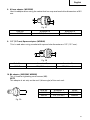
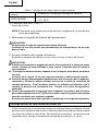
1. Using the convenient hook
The convenient hook can be installed on the right
or left side and the angle can be adjusted in 5 steps
between 0 and 80.
(1) Operating the hook
(a) Pull out the hook toward you in the direction of
arrow (A) and turn in the direction of arrow (B).
(Fig. 5)
(b) The angle can be adjusted in 5 steps (0°, 20°, 40°,
60°, 80°).
Adjust the angle of the hook to the desired
position for use.
(2) Switching the hook position
CAUTION:
● If the tool falls, there is a risk that malfunction and/
or physical damage can occur. It is recommended
that you also use fall-preventing wires, etc.
● Incomplete installation of the hook may result in
bodily injury when used.
(a) Securely hold the main unit and remove the
screw using a slotted head screwdriver or a
coin. (Fig. 6)
(b) Remove the hook and spring. (Fig. 7)
(c) Install the hook and spring on the other side
and securely fasten with screw. (Fig. 8)
NOTE:
Pay attention to the spring orientation. Install
the spring with larger diameter away from you.
(Fig. 8)
Fig. 6
Fig. 8
Fig. 7
Convenient Hook
Fig. 5
Spring
Larger diameter
faces away

English
16
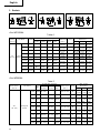
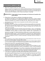
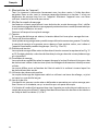
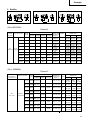
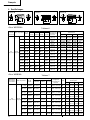
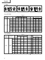
2. Selecting the socket matched to the bolt
Be sure to use a socket which is matched to the bolt
to be tightened. Using an improper socket will not
only result in insufficient tightening but also in
damage to the socket or nut.
A worn or deformed hex or square-holed socket
will not give an adequate tightness for fitting to the
nut or anvil, consequently resulting in loss of tight-
ening torque.
Pay attention to wear of socket hole, and replace
before further wear has developed.
Matching socket and bolt sizes are shown Tables 4,
5, 6 and 7. The numerical value of a socket
designation denotes the side-to-side distance (H)
of its hex. hole.
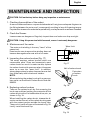
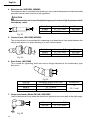
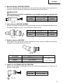
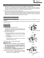
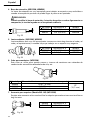
3. Installing a socket (Fig. 9, 10)
Align the plunger located in the square part of the
anvil with the hole in the hex. socket. Then push the
plunger, and mount the hex. socket on the anvil.
Check that the plunger is fully engaged in the hole.
When removing the socket, reverse the sequence.
4. Removing the socket
Please do the opposite point on the method of
installing socket.
5. Confirm that the battery is mounted correctly.
6. Check the rotational direction
The bit rotates clockwise (viewed from the rear
side) by pushing the R-side of the push button.
The L-side of the push button is pushed to turn the
bit counterclockwise. (See Fig. 11). (The
L
and
R
marks are engraved on the body.)
CAUTION
The push button can not be switched while the impact driver is turning. To switch the
push button, stop the impact driver, then set the push button.
7. Switch operation
䡬 When the trigger switch is depressed, the tool rotates. When the trigger is released, the
tool stops.
䡬 The rotational speed can be controlled by varying the amount that the trigger switch is
pulled. Speed is low when the trigger switch is pulled slightly and increases as the trigger
switch is pulled more.
NOTE
A buzzing noise is produced when the motor is about to rotate; this is only a noise, not
a machine failure.
Plunger
Anvil
Hole
Fig. 10
Hexagonal
socket
Fig. 11
R
L
Push
Push
Push
button
Fig. 9
Groove
Hexagonal
socket
Anvil

English
17
8. Tightening and loosening bolts
A hex socket matching the bolt or nut must first be selected. Then mount the socket on
the anvil, and grip the nut to be tightened with the hex socket. Holding the wrench in line
with the bolt, press the power switch to impact the nut for several seconds.
If the nut is only loosely fitted to the bolt, the bolt may turn wit the nut, therefore mistaking
proper tightening. In this case, stop impact on the nut and hold the bolt head with a
wrench before restarting impact, or manually tighten the bolt and nut to prevent them
slipping.
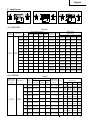
9. Number of bolt tightened possible
Please refer to the table below for the number of bolt tightened possible with one charge.
<For WR12DM> (EB1220BL)
<For WR9DM> (EB9B)
These values may vary slightly, according to surrounding temperature and battery
characteristics.
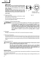
OPERATIONAL CAUTIONS
1. Resting the unit after continuous work
After use for continuous bolt-tightening work, rest the unit for 15 minutes or so when
replacing the battery. The temperature of the motor, switch, etc., will rise if the work is
started again immediately after battery replacement, eventually resulting in burnout.
CAUTION: Do not touch the hammer case, as it gets very hot during continuous
work.
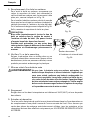
2. Cautions on use of the speed control switch
This switch has a built-in, electronic circuit which steplessly varies the rotation speed.
Consequently, when the switch trigger is pulled only slightly (low speed rotation) and the
motor is stopped while continuously driving in screws, the components of the electronic
circuit parts may overheat and be damaged.
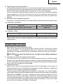
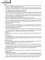
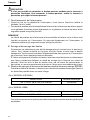
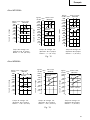
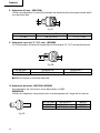
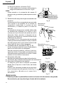
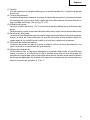
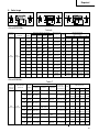
3. Tightening torque
Refer to Fig. 12 and 13 for the tightening torque of bolts (according to size), under the
conditions shown in Fig. 14. Please use this example as a general reference, as tightening
torque will vary according to tightening conditions.
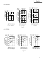
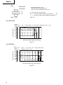
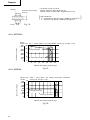
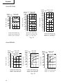
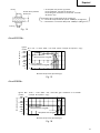
Tightening torque varies, depending on the battery’s charge level. Fig. 15 and 16 shows
an example of the relationship between tightening torque and the number of tightenings
(WR12DM and WR9DM). As shown, tightening torque gradually weakens with the
increase in the number of tightenings. In particular, as the torque decreases very close
to the complete discharge (“a” margin in graph), the unit’s impact weakens, the number
of time impacts declines and tightening torque drops off abruptly. If this occurs, check
torque level, then recharge the battery if necessary.
Bolt used No. of tightenings
5/8" × 2–5/32" (M16 × 55) F10T bolt Approx. 90
Bolt used No. of tightenings
Ordinary bolt 15/32" × 1–3/4" (M12 × 45) Approx. 90

English
18
NOTE
䡬 If a long striking time is used, screws will be strongly tightened. This may cause the screw
to break, or may damage the end of the bit.
䡬 If the unit is held at an angle to the screw being tightened, the head of the screw may be
damaged, or the specified torque may not be transmitted to the screw. Always keep the
unit and the screw being tightened in a straight line.
4. Use a tightening time suitable for the screw
The appropriate torque for a screw differs according to the material and size of the screw,
and the material being screwed etc., so please use a tightening time suitable for the
screw. In particular, if a long tightening time is used in the case of screws smaller than
5/16" (8 mm), there is a danger of the screw breaking, so please confirm the tightening
time and the tightening torque beforehand.
5. Work at a tightening torque suitable for the bolt under impact
The optimum tightening torque for nuts or bolts differs with material and size of the nuts
or bolts. An excessively large tightening torque for a small bolt may stretch or break the
bolt. The tightening torque increases in proportionate to the operaton time. Use the
correct operating time for the bolt.
6. Holding the tool
Hold the impact wrench firmly with both hands. In this case hold the wrench in line with the bolt.
It is not necessary to push the wrench very hard. Hold the wrench with a force just
sufficient to counteract the impact force.
7. Confirm the tightening torque
The following factors contribute to a reduction of the tightening torque. So confirm the
actual tightening torque needed by screwing up some bolts before the job with a hand
torque wrench. Factors affecting the tightening torque are as follows.
(1) Voltage
When the discharge margin is reached, voltage decreases and tightening torque is
lowered.
(2) Operating time
The tightening torque increases when the operating time increases. But the tightening
torque does not increase above a certain value even if the tool is driven for a long time.
(See Fig. 12 and 13)
(3) Diameter of bolt
The tightening torque differs with the diameter of the bolt as shown in Fig. 12 and 13.
Generally a larger diameter bolt requires larger tightening torque.
(4) Tightening conditions
The tightening torque differs according to the torque ratio; class, and length of bolts even
when bolts with the same size threads are used. The tightening torque also differs
according to the condition of the surface of workpiece through which the bolts are to be
tightened. When the bolt and nut turn together, torque is greatly reduced.
(5) Using optional parts
The tightening torque is reduced a little when an extension bar, universal joint or a long
socketis used.
(6) Clearance of the socket
A worn or deformed hex or a square-holed socket will not give an adequate tightness to
the fitting between the nut or anvil, consequently resulting in loss of tightening torque.
Using an improper socket which does not match to the bolt will result in an insufficient
tightening torque. Matching socket and bolt sizes are shown in Table 4, 5, 6 and 7.

English
19
1000
(868)
800
(694)
600
(521)
400
(347)
200
(174)
0
100
80
60
40
20
0
0
1 2 3
1000
(868)
800
(694)
600
(521)
400
(347)
200
(174)
0
100
80
60
40
20
0
0
1 2 3
1000
(868)
800
(694)
600
(521)
400
(347)
200
(174)
0
100
80
60
40
20
0
0
1 2 3
1000
(868)
800
(694)
600
(521)
400
(347)
200
(174)
0
0 1
2
3
100
80
60
40
20
0
1400
(1215)
1200
(1642)
1000
(868)
800
(694)
600
(521)
400
(347)
200
(174)
0
0 1
2
3
140
120
100
80
60
40
20
0
1600
(1389)
1400
(1215)
1200
(1042)
1000
(868)
800
(694)
600
(521)
400
(347)
200
(174)
0
0 1
2
3
160
140
120
100
80
60
40
20
0
Tightening time: sec
(Steel plate thickness
t = 1" (25 mm))
Fig. 12
Tightening time: sec
(Steel plate thickness
t = 1" (25 mm))
Tightening torque
Tightening torque
Tightening torque
High strenge bolt
High strenge bolt
High strenge
bolt
Ordinary bolt
Ordinary bolt
Ordinary bolt
kgf·cm
N·m
3/8"×1-5/32"
(in-lbs) (M10×30)
kgf·cm
N·m
15/32"×1-3/4"
(in-lbs) (M12×45)
kgf·cm
N·m
9/16"×1-15/16"
(in-lbs) (M14×50)
<For WR12DM>
Tightening time: sec
(Steel plate thickness
t = 3/8" (10 mm))
<For WR9DM>
Tightening time: sec
(Steel plate thickness
t = 3/8" (10 mm))
Tightening time: sec
(Steel plate thickness
t = 3/8" (10 mm))
Fig. 13
Tightening time: sec
(Steel plate thickness
t = 1" (25 mm))
Tightening torque
Tightening torque
Tightening torque
High strenge
bolt
High strenge bolt
High strenge bolt
Ordinary bolt
Ordinary bolt
Ordinary bolt
kgf·cm
N·m
3/8"×1-3/6"
(in-lbs) (M10×30)
kgf·cm
N·m
15/32"×1-3/4"
(in-lbs) (M12×45)
kgf·cm
N·m
5/16"×1-3/6"
(in-lbs) (M8×30)

English
20
1600
(1389)
1200
(1042)
800
(694)
400
(347)
0
0
20 40
60
80 100 120 140 160
160
120
80
40
0
a
1600
(1389)
1200
(1042)
800
(694)
400
(347)
0
0
20
40
60
80
100 120 140
160
120
80
40
0
a
Fig. 14
Bolt
Nut
Steel plate
thickness t
Explanation of strength grade:
4 — Yield point of bolt: 45,500 psi (32 kgf/mm
2
)
8 — Pulling strength of bolt: 56,900 psi (40 kgf/mm
2
)
*The following bolt is used.
Ordinary bolt: Strength grade 4.8
High tensile bolt: Hardness division 12.9
()
Number of tightenings (PCS)/charging
Fig. 15
Tightening torque
kgf·cm
N·m 5/8" × 2–5/32" (M16 × 55) F10T bolt (tightening time 3 sec)
(in-lbs)
<For WR12DM>
Number of tightenings (PCS)/charging
Fig. 16
Tightening torque
When full recharged
When complately discharged
<For WR9DM>
When full recharged
When complately discharged
kgf·cm
N·m 15/32" × 1–3/4" (M12 × 45) High tension bolt
(in-lbs)
(tightening time 3 sec)
La page est en cours de chargement...
La page est en cours de chargement...
La page est en cours de chargement...
La page est en cours de chargement...
La page est en cours de chargement...
La page est en cours de chargement...
La page est en cours de chargement...
La page est en cours de chargement...
La page est en cours de chargement...
La page est en cours de chargement...
La page est en cours de chargement...
La page est en cours de chargement...
La page est en cours de chargement...
La page est en cours de chargement...
La page est en cours de chargement...
La page est en cours de chargement...
La page est en cours de chargement...
La page est en cours de chargement...
La page est en cours de chargement...
La page est en cours de chargement...
La page est en cours de chargement...
La page est en cours de chargement...
La page est en cours de chargement...
La page est en cours de chargement...
La page est en cours de chargement...
La page est en cours de chargement...
La page est en cours de chargement...
La page est en cours de chargement...
La page est en cours de chargement...
La page est en cours de chargement...
La page est en cours de chargement...
La page est en cours de chargement...
La page est en cours de chargement...
La page est en cours de chargement...
La page est en cours de chargement...
La page est en cours de chargement...
La page est en cours de chargement...
La page est en cours de chargement...
La page est en cours de chargement...
La page est en cours de chargement...
La page est en cours de chargement...
La page est en cours de chargement...
La page est en cours de chargement...
La page est en cours de chargement...
La page est en cours de chargement...
La page est en cours de chargement...
La page est en cours de chargement...
La page est en cours de chargement...
La page est en cours de chargement...
La page est en cours de chargement...
La page est en cours de chargement...
La page est en cours de chargement...
La page est en cours de chargement...
La page est en cours de chargement...
La page est en cours de chargement...
La page est en cours de chargement...
La page est en cours de chargement...
La page est en cours de chargement...
La page est en cours de chargement...
La page est en cours de chargement...
La page est en cours de chargement...
La page est en cours de chargement...
La page est en cours de chargement...
La page est en cours de chargement...
La page est en cours de chargement...
La page est en cours de chargement...
La page est en cours de chargement...
La page est en cours de chargement...
-
 1
1
-
 2
2
-
 3
3
-
 4
4
-
 5
5
-
 6
6
-
 7
7
-
 8
8
-
 9
9
-
 10
10
-
 11
11
-
 12
12
-
 13
13
-
 14
14
-
 15
15
-
 16
16
-
 17
17
-
 18
18
-
 19
19
-
 20
20
-
 21
21
-
 22
22
-
 23
23
-
 24
24
-
 25
25
-
 26
26
-
 27
27
-
 28
28
-
 29
29
-
 30
30
-
 31
31
-
 32
32
-
 33
33
-
 34
34
-
 35
35
-
 36
36
-
 37
37
-
 38
38
-
 39
39
-
 40
40
-
 41
41
-
 42
42
-
 43
43
-
 44
44
-
 45
45
-
 46
46
-
 47
47
-
 48
48
-
 49
49
-
 50
50
-
 51
51
-
 52
52
-
 53
53
-
 54
54
-
 55
55
-
 56
56
-
 57
57
-
 58
58
-
 59
59
-
 60
60
-
 61
61
-
 62
62
-
 63
63
-
 64
64
-
 65
65
-
 66
66
-
 67
67
-
 68
68
-
 69
69
-
 70
70
-
 71
71
-
 72
72
-
 73
73
-
 74
74
-
 75
75
-
 76
76
-
 77
77
-
 78
78
-
 79
79
-
 80
80
-
 81
81
-
 82
82
-
 83
83
-
 84
84
-
 85
85
-
 86
86
-
 87
87
-
 88
88


Hitachi WR 9DM Safety Instructions And Instruction Manual
- Taper
- Safety Instructions And Instruction Manual
- Ce manuel convient également à
dans d''autres langues
- English: Hitachi WR 9DM
- español: Hitachi WR 9DM
Documents connexes
-
Hitachi WR 16SA S Safety And Instruction Manual
-
-
-
Hitachi WR 9DM Manuel utilisateur
-
-
Hitachi WH 12DM2 Manuel utilisateur
-
-
-
-