Kohler 99572-TLC-NA Guide d'installation
- Taper
- Guide d'installation

Installation and Care Guide
Lighted Mirror
K-99571-TL, K-99572-TL, K-99573-TL
Français, page“ Français-1”
Español, página“ Español-1”
1292979-2-A

IMPORTANT SAFETY INSTRUCTIONS
When using electrical products, basic precautions should always be followed, including the following:
Read all instructions before using or installing this product.
WARNING: Risk of electric shock. Grounding is required for the outlets within the power box.
Connect only to a circuit protected by a Class A Ground-Fault Circuit-Interrupter (GFCI)* which
protects against line-to-ground shock hazard. Use 120 V, 15 A service.
WARNING: Risk of electric shock. A qualified electrician must route all electrical wiring for the
product. Improper installation will create an electrical hazard and may not comply with local
building and electrical codes.
WARNING: Risk of electric shock. Turn the electricity off at the circuit breaker or fuse box before
moving, testing, cleaning, or repairing this product. When unplugged, the electric supply will no
longer be electrically live, which will eliminate the risk of electric shock.
CAUTION: Risk of electric shock. Risk of electric shock. Electrical wiring may need to be
relocated.
NOTICE: Follow all local building, electrical, and plumbing codes.
IMPORTANT! A dimmer switch is required. This product is compatible with most residential dimmers
intended for incandescent and dimmable LED bulbs. For optimal dimming performance, a programmable
digital fade dimmer intended for LED lighting with a minimum rating of 150 W is recommended.
*Outside North America, this device may be known as a Residual Current Device (RCD).
SAVE THESE INSTRUCTIONS
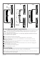
Specifications
Electrical Service
Light 120 V, 60 Hz, 0.8 A
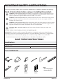
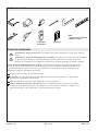
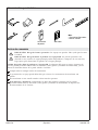
Tools and Materials
Stud
Finder
Dimmer
Switch
Plus:
• Wire Cutter/Stripper
• Assorted Drill Bits
1292979-2-A 2 Kohler Co.

Before You Begin
CAUTION: Risk of personal injury. Mirrors are heavy. Get assistance lifting the unit.
CAUTION: Risk of product or property damage. Swinging panels that are misaligned or set too
close to the main mirror can chip or break. If needed, make adjustments to properly align the
panels with the main mirror.
NOTICE: Risk of product or property damage. The location of the mirror is critical. Make sure the
swinging panels will clear all obstacles (such as a faucet or light fixture), and obstacles behind the finished
wall will not be damaged during the drilling process.
Observe all local building codes.
The appearance of your mirror may differ from the mirror illustrated. The installation instructions
still apply.
This installation is easiest when performed by two people.
For K-99572-TL and K-99573-TL: When determining the height of the product, verify the swinging
panels will clear all obstacles (such as a faucet or light fixture). A minimum distance of 3″ (76 mm)
is required.
Kohler Co. 3 1292979-2-A

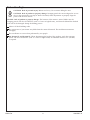
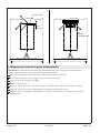
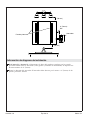
Roughing-In Information
For K-99572-TL and K-99573-TL: When determining the location of the mirror, verify the swinging
panels will clear all obstacles (such as a faucet or light fixture). A minimum distance of 3″ (76 mm)
is required.
Plan for the location of the dimmer switch. The switch should be located at least 3″ (76 mm) from
the unfolded swinging panels.
3" (76 mm)
Dimmer Switch
Swinging Panels
3" (76 mm)
Min
3" (76 mm)
1292979-2-A 4 Kohler Co.

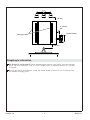
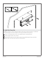
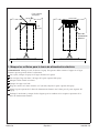
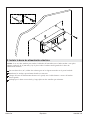
1. Mark the Power Bar Holes
IMPORTANT! Get assistance when positioning the mirror. One person should hold the mirror in place
while the other person marks the placement.
With help, position the mirror in the desired location on the wall.
Using a pencil, draw a line across the top of the mirror.
Mark the centerline on the line.
Set the mirror aside.
Make a mark on the centerline 2-1/2″ (64 mm) down from the top of the mirror.
Align the top of the power bar with the line for the top of the mirror.
Verify level and mark the two hole locations at the top corners of the power bar.
2-1/2"
(64 mm)
Top of Mirror
Power
Bar
Kohler Co. 5 1292979-2-A

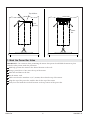
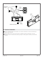
2. Route the Wiring
Drill a 3/4″ (19 mm) hole for the electrical wire location.
Route the electrical wiring from the dimmer switch through the hole in the finished wall.
The wiring should extend at least 6″ (152 mm) from the hole.
6"
(152 mm)
2-1/2"
(64 mm)
Ø 3/4"
1292979-2-A 6 Kohler Co.

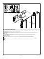
3. Install the Power Bar
NOTICE: If conduit is used for routing the dimmer switch wiring, attach the conduit to a 4″ (102 mm)
square electrical plate and secure the plate over the large central hole of the power bar.
Using a 3/16″ drill bit, drill two holes at the marked locations on the finished wall.
Insert the supplied anchors where needed.
Position the power bar on the wall, with the electrical wire pulled through the large central hole.
Verify the bar is level, then secure with two screws provided.
3/16"
Kohler Co. 7 1292979-2-A

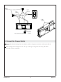
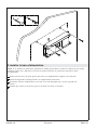
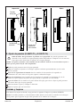
4. Connect the Dimmer Switch
Connect the electrical wiring from the dimmer switch to the proper connectors on the power bar as
shown.
Feed the light cables through the slots and tape to the top of the power bar to keep the cables
accessible for later connection.
Load
(Black)
Wire
Connectors
Line
(White)
Wire Connector
Ground
(Green)
Light
Cables
1292979-2-A 8 Kohler Co.

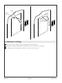
5. Position the Mirror
IMPORTANT! Get assistance when hanging the mirror.
IMPORTANT! For K-99572-TL and K-99573-TL: Never leave the swinging panels unsupported during
installation.
For K-99572-TL and K-99573-TL: To ease installation, fold the swinging panels against the main
mirror.
Align the ″J″ hooks on the mirror with the slots in the power bar.
Lower the ″J″ hooks into the slots. The mirror will initially lower approximately 1/4″ (6 mm).
Push the mirror toward the wall to further engage the ″J″ hooks into the slots.
"J" Hook
Kohler Co. 9 1292979-2-A

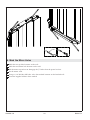
6. Mark the Mirror Holes
Mark the two top hole locations on the wall.
Mark the two bottom hole locations on the wall.
Lift the mirror up and out to disengage the ″J″ hooks from the power bar slots.
Set the mirror aside.
Using a 3/16″ drill bit, drill holes at the four marked locations on the finished wall.
Insert the supplied anchors where needed.
3/16"
1292979-2-A 10 Kohler Co.

7. Secure the Mirror
Reinstall the mirror to the power bar by engaging the ″J″ hooks with the slots. Refer to the ″Position
the Mirror″ section.
Secure the mirror to the finished wall with four screws provided.
Kohler Co. 11 1292979-2-A

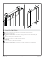
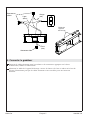
8. Connect the Light Cables
Connect the two light cables from the mirrors to the connectors from the power box.
Tuck the wires into the mirror.
For K-99572-TL and K-99573-TL: Verify that the swinging panels move freely without binding the
cables.
Turn on the electrical power to the dimmer switch.
Use the dimmer switch to test the lights for proper operation.
Install the Caps
Press the caps to the top and bottom of the mirror.
For K-99572-TL and K-99573-TL: Install the caps to the top and bottom of the swinging panels.
1292979-2-A 12 Kohler Co.

9. Panel Adjustment (K-99572-TL and K-99573-TL)
CAUTION: Risk of product or property damage. Swinging panels that are misaligned or set too
close to the main mirror can chip or break. If needed, make adjustments to properly align the
panels with the main mirror.
NOTICE: Alignment of the swinging panels is set at the factory. Adjustments should not be necessary
unless the panels have been replaced.
Fold the swinging panel against the main mirror.
Loosen the lock screws on the top and bottom hinge approximately 1/4 turn clockwise.
Tight Gap Adjustment: Turn the jack screws counterclockwise in 1/4 turn increments at the top
and bottom of the mirror.
Tilt Adjustment: Turn the jack screw counterclockwise in 1/4 turn increments at the top or bottom
of the mirror, whichever has the tighter gap.
Height Adjustment: Turn the screw at the bottom of the mirror to raise or lower the swinging panel
to the same height as the main mirror.
Slowly unfold the panel and check alignment.
Repeat the adjustments as needed.
Care and Cleaning
For best results, keep the following in mind when caring for your KOHLER product:
NOTE: Periodic care and maintenance should include checking all hinge screws on the door to make sure
they are tight and engaged in the hinge holes.
•
Do not let cleaners sit or soak on surfaces.
Gap
Tilt
Height
Adjust the
tighter gap.
Jack Screws
Lock
Screws
Kohler Co. 13 1292979-2-A

Care and Cleaning (cont.)
For detailed cleaning information and products to consider, visit www.kohler.com/clean. To order Care &
Cleaning information, call 1-800-456-4537.
Warranty
ONE-YEAR LIMITED WARRANTY
KOHLER plumbing products are warranted to be free of defects in material and workmanship for one year
from date of installation.
Kohler Co. will, at its election, repair, replace or make appropriate adjustment where Kohler Co. inspection
discloses any such defects occurring in normal usage within one (1) year after installation. Kohler Co. is not
responsible for removal or installation costs. Use of in-tank toilet cleaners will void the warranty.
To obtain warranty service contact Kohler Co. either through your Dealer, Plumbing Contractor, Home
Center or E-tailer, or by writing Kohler Co., Attn.: Customer Care Center, 444 Highland Drive, Kohler, WI
53044, USA, or by calling 1-800-4-KOHLER (1-800-456-4537) from within the USA and Canada, and
001-800-456-4537 from within Mexico, or visit www.kohler.com within the USA, www.ca.kohler.com from
within Canada, or www.mx.kohler.com in Mexico.
IMPLIED WARRANTIES INCLUDING THAT OF MERCHANTABILITY AND FITNESS FOR A
PARTICULAR PURPOSE ARE EXPRESSLY LIMITED IN DURATION TO THE DURATION OF THIS
WARRANTY. KOHLER CO. AND/OR SELLER DISCLAIM ANY LIABILITY FOR SPECIAL,
INCIDENTAL OR CONSEQUENTIAL DAMAGES. Some states/provinces do not allow limitations on how
long an implied warranty lasts, or the exclusion or limitation of special, incidental or consequential damages,
so these limitations and exclusions may not apply to you. This warranty gives you specific legal rights. You
may also have other rights which vary from state/province to state/province.
This is Kohler Co.’s exclusive written warranty.
1292979-2-A 14 Kohler Co.

Guide d’installation et d’entretien
Miroir lumineux
INSTRUCTIONS IMPORTANTES DE SÉCURITÉ
Lors de l’utilisation de produits électriques, toujours observer les précautions de base, notamment:
Lire toutes les instructions avant d’utiliser ou d’installer ce
produit.
AVERTISSEMENT: Risque de choc électrique. Une mise à la terre est requise pour les prises
comprises dans le boîtier électrique. Seulement raccorder à un circuit qui est protégé par un
disjoncteur de fuite de terre (GFCI)* de Classe A qui protège contre les risques d’électrocution de
tension phase-terre. Utiliser un service de 120 V, 15 A.
AVERTISSEMENT: Risque de choc électrique. Tout le câblage électrique pour le produit doit être
réalisé par un électricien qualifié. Une installation non adéquate crée un risque électrique et pourrait
ne pas être conforme aux codes de construction et d’électricité locaux.
AVERTISSEMENT: Risque de choc électrique. Couper l’électricité au niveau du disjoncteur ou du
boîtier de fusibles avant de déplacer, de tester, de nettoyer ou de réparer ce produit. Lorsqu’il est
débranché, l’alimentation électrique ne sera plus sous tension, ce qui éliminera le risque de choc
électrique.
ATTENTION: Risque de choc électrique. Risque de choc électrique. Il sera peut-être nécessaire de
déplacer le câblage électrique.
AVIS: Suivre tous les codes d’électricité, de plomberie et de bâtiment locaux.
IMPORTANT! Un gradateur est requis. Ce produit est compatible avec la plupart des gradateurs
résidentiels destinés à des ampoules à DEL incandescentes et à commande d’intensité. Pour obtenir une
performance de commande d’intensité optimale, un gradateur de fondu numérique destiné à un éclairage
à DEL avec une intensité nominale minimum de 150 W est recommandé.
* Hors de l’Amérique du Nord, ce dispositif peut être connu sous le nom de dispositif à courant résiduel
(RCD).
CONSERVER CES INSTRUCTIONS
Spécifications
Service électrique
Éclairage 120 V, 60 Hz, 0,8 A
Kohler Co. Français-1 1292979-2-A

Outils et matériel
Avant de commencer
ATTENTION: Risque de blessures. Les miroirs sont lourds. Demander de l’aide pour soulever
l’unité.
ATTENTION: Risque d’endommagement du produit. Les panneaux pivotants qui sont désalignés
ou qui sont placés trop près du miroir principal peuvent s’ébrécher ou se briser. Au besoin,
effectuer des ajustements pour aligner les panneaux sur le miroir principal de manière adéquate.
AVIS: Risque d’endommagement du produit. L’emplacement du miroir est de première importance.
S’assurer que les panneaux pivotants seront dégagés de tous les obstacles (comme un robinet ou un
appareil d’éclairage), et que les obstacles qui se trouvent à l’arrière du mur fini ne subiront pas de
dommages pendant la procédure de perçage.
Respecter tous les codes de construction locaux.
L’apparence de votre miroir pourrait être différente de celle du miroir illustré. Les instructions
d’installation s’appliquent tout de même.
Cette installation est exécutée le plus facilement par deux personnes.
Pour les modèles K-99572-TL et K-99573-TL: Lors de l’établissement de la hauteur du produit,
vérifier que les panneaux pivotants sont dégagés de tous les obstacles (comme un robinet ou un
appareil d’éclairage). Une distance de 3″ (76 mm) minimum est requise.
Localisateur
de montants
Gradateur
Plus:
• Coupe-fil/Outil à dénuder
• Mèches assorties
1292979-2-A Français-2 Kohler Co.

Information sur l’installation brute
Pour les modèles K-99572-TL et K-99573-TL: Lors de la détermination de l’emplacement du miroir,
vérifier que les panneaux pivotants sont dégagés de tous obstacles (comme un robinet ou un
appareil d’éclairage). Une distance de 3″ (76 mm) minimum est requise.
Prévoir l’emplacement pour le gradateur. Le gradateur doit être placé à une distance de 3″ (76 mm)
au moins des panneaux pivotants dépliés.
3" (76 mm)
Gradateur
3" (76 mm)
Min
3" (76 mm)
Panneaux pivotants
Kohler Co. Français-3 1292979-2-A

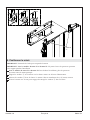
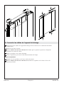
1. Marquer les trous de la barre d’alimentation
IMPORTANT! Demander de l’aide pour le positionnement du miroir. Une personne devrait tenir le
miroir en place tandis que l’autre personne marque l’emplacement.
Avec de l’aide, positionner le miroir dans l’emplacement souhaité sur le mur.
Utiliser un crayon pour tirer une ligne au travers du haut du miroir.
Tracer le repère de centrage sur la ligne.
Mettre le miroir de côté.
Tracer un repère sur le repère de centrage à 2-1/2″ (64 mm) vers le bas à partir du haut du miroir.
Aligner le dessus de la barre d’alimentation sur la ligne pour le haut du miroir.
Vérifier le niveau et marquer les emplacements des deux trous dans les coins supérieurs de la barre
d’alimentation.
2-1/2"
(64 mm)
Haut du miroir
Barre
d'alimentation
1292979-2-A Français-4 Kohler Co.

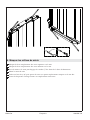
2. Acheminer le câblage
Percer un trou de 3/4 (19 mm) pour l’emplacement du fil électrique.
Acheminer le câblage électrique entre le gradateur à travers le trou dans le mur fini.
Le câblage doit se prolonger de 6″ (152 mm) au moins au-delà du trou.
6"
(152 mm)
2-1/2"
(64 mm)
Ø 3/4"
Kohler Co. Français-5 1292979-2-A

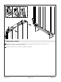
3. Installer la barre d’alimentation
AVIS: Si un conduit est utilisé pour acheminer le câblage du gradateur, attacher le conduit sur une plaque
électrique carrée de 4″ (102 mm) et sécuriser la plaque par-dessus le grand trou central de la barre
d’alimentation.
Utiliser un foret de 3/16″ pour percer deux trous aux emplacements marqués sur le mur fini.
Insérer les dispositifs d’ancrage fournis aux emplacements nécessaires.
Positionner la barre d’alimentation sur le mur, avec le fil électrique tiré à travers le grand trou
central.
Vérifier que la barre est de niveau, puis la sécuriser avec deux vis fournies.
3/16"
1292979-2-A Français-6 Kohler Co.
La page est en cours de chargement...
La page est en cours de chargement...
La page est en cours de chargement...
La page est en cours de chargement...
La page est en cours de chargement...
La page est en cours de chargement...
La page est en cours de chargement...
La page est en cours de chargement...
La page est en cours de chargement...
La page est en cours de chargement...
La page est en cours de chargement...
La page est en cours de chargement...
La page est en cours de chargement...
La page est en cours de chargement...
La page est en cours de chargement...
La page est en cours de chargement...
La page est en cours de chargement...
La page est en cours de chargement...
La page est en cours de chargement...
La page est en cours de chargement...
La page est en cours de chargement...
La page est en cours de chargement...
La page est en cours de chargement...
La page est en cours de chargement...
-
 1
1
-
 2
2
-
 3
3
-
 4
4
-
 5
5
-
 6
6
-
 7
7
-
 8
8
-
 9
9
-
 10
10
-
 11
11
-
 12
12
-
 13
13
-
 14
14
-
 15
15
-
 16
16
-
 17
17
-
 18
18
-
 19
19
-
 20
20
-
 21
21
-
 22
22
-
 23
23
-
 24
24
-
 25
25
-
 26
26
-
 27
27
-
 28
28
-
 29
29
-
 30
30
-
 31
31
-
 32
32
-
 33
33
-
 34
34
-
 35
35
-
 36
36
-
 37
37
-
 38
38
-
 39
39
-
 40
40
-
 41
41
-
 42
42
-
 43
43
-
 44
44


