

2
EN
Contents Full Ceramic Gravity Discharge Toilet
1 Explanation of Symbols and Safety
Instructions ............................ 3
1.1 Recognize Safety Information .............3
1.2 Understand Signal Words ................3
1.3 Supplemental Directives .................3
1.4 General Safety Messages ................3
2 Intended Use ........................... 4
3 General Information ..................... 4
3.1 Recommended Spare Parts ..............4
3.2 Wiring Diagram ........................4
4 Operation .............................. 5
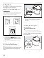
4.1 Using the Flush Touch Panel or Flush Switch .5
4.2 Using the Flush Handle ..................5
4.3 Using the Bidet Option ..................5
4.4 Understanding the Indicator Lights ........6
4.5 Changing the Flush Modes ..............6
4.6 Initializing the Toilet System ..............6
4.7 Using the Manual Override Function .......6
4.8 Using the Service Mode Function .........7
5 Maintenance ........................... 7
5.1 Cleaning the Toilet .....................7
5.2 Setting an Inspection Schedule ...........7
5.3 Preparing the Toilet for an Extended Period of
Non-Use ..............................7
5.4 Winterizing the Toilet ...................8
6 Troubleshooting ........................ 8
6.1 Troubleshooting Guide ..................9
7 Service Procedures ......................11
7.1 Aligning the Cam Switch/Flush Ball .......11
7.2 Removing the Toilet from the Floor .......12
7.3 Replacing the Flush Ball Seal ............12
7.4 Replacing the Flush Ball ................12
7.5 Replacing the Rotor Shaft ...............13
7.6 Replacing the Rotor Shaft Cam ...........13
7.7 Replacing the Motor Drive Arm ..........13
7.8 Replacing the Drive Linkage .............13
8 Disposal .............................. 14
LIMITED WARRANTY ...................... 14
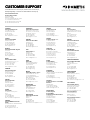
Customer Support. . . . . . . . . . . . . . . . . . . . . . . . . 28
Read these instructions carefully.
These instructions MUST stay with this product.
Contents

3
EN
Full Ceramic Gravity Discharge Toilet Explanation of Symbols and Safety Instructions
1 Explanation of Symbols and
Safety Instructions
This manual has safety information and instructions to
help you eliminate or reduce the risk of accidents
and injuries.
1.1 Recognize Safety Information
This is the safety alert symbol. It is used to alert
you to potential physical injury hazards. Obey all
safety messages that follow this symbol to avoid
possible injury or death.
1.2 Understand Signal Words
A signal word will identify safety messages and property
damage messages, and will indicate the degree or level
of hazard seriousness.
DANGER!
Indicates a hazardous situation that, if not avoided,
will result in death or serious injury.
WARNING
Indicates a hazardous situation that, if not avoided,
could result in death or serious injury.
CAUTION
Indicates a hazardous situation that, if not avoided,
could result in minor or moderate injury.
NOTICE: Used to address practices not related to
physical injury.
I
Indicates additional information that is not related
to physical injury.
1.3 Supplemental Directives
To reduce the risk of accidents and injuries, please
observe the following directives before proceeding to
operate or service this appliance:
• Read and follow all safety information and instructions
to avoid possible injury or death.
• Read and understand these instructions before
operation or servicing of this product.
• Any parts installed during servicing must comply with
all applicable local or national codes, including the
latest edition of the following standards:
U.S.A.
– ANSI/NFPA70, National Electrical Code (NEC)
– ANSI/NFPA 1192, Recreational Vehicles Code
– ABYC guidelines for marine installations
Canada
– CSA C22.1, Parts l & ll, Canadian Electrical Code
– CSA Z240 RV Series, Recreational Vehicles
1.4 General Safety Messages
WARNING: ELECTRICAL SHOCK, FIRE,
FLOOD, AND/OR EXPLOSION HAZARD.
Failure to obey the following warnings could
result in death or serious injury:
• Use only Dometic replacement parts and
components that are specifically approved for use
with the appliance.
• This product must be installed and serviced by a
qualified service technician.
• Do not modify this product in any way. Modifi cation
can be extremely hazardous.
• Before beginning maintenance or service on this
product, be sure that all electrical power to the unit
has been turned off, and for marine applications,
ensure that seacocks are in the closed or off position.
• For toilets in marine applications connected to any
through-the-hull fittings: always close seacocks when
the toilet is not in use (even if the boat is unattended
for a brief period).
• For marine applications, instruct all passengers on
how to safely close the valves when the toilet is not in
use.
• For toilets using fresh water for flushing, disconnect
any shoreside or municipal water connections when
the boat or RV is unattended for any length of time.
NOTICE: RISK OF PROPERTY DAMAGE. Failure to
follow the following notices may cause damage to the
toilet or toilet system:

4
EN
Intended Use Full Ceramic Gravity Discharge Toilet
• Only flush water, bodily wastes, and rapid-dissolving
toilet tissue.
• Do not overfill the holding tank, or serious damage
can occur to the sanitation system. Overfilling the
holding tank can rupture the holding tank or release
tank contents into the bilge or into the RV.
2 Intended Use
The 4300, 4400, and 6500 series toilets are designed
and intended for use only inside a boat or recreational
vehicle (hereinaer referred to as “RV”) for which it is
supplied.
Use these instructions to ensure correct operation of
the toilet. Dometic Corporation accepts no liability for
damage in the following cases:
• Faulty assembly or connection
• Damage to the product resulting from mechanical
influences and excess voltage
• Alterations to the product without expressed
permission from Dometic Corporation
• Use for purposes other than those described in the
operating manual
Dometic Corporation reserves the right to modify
appearances and specifications without notice.
3 General Information
This section provides reference information on the
components, wiring, and recommended spare parts to
keep in stock for the toilet.
I
The images used in this document are for reference
purposes only. Components and component
locations may vary according to specific product
models. Measurements may vary ±0.38 in.
(10 mm).
3.1 Recommended Spare Parts
When operating a boat or other vehicle in remote
areas, keep the following spare parts on hand to assure
continuous toilet system operation.
Name Part Number
Flush ball seal
See separately packaged
parts list for part number.
Flush ball
Electric water valve
Vacuum breaker assembly
I
To order spare parts, refer to "Customer Support"
on page 28 for contact information.
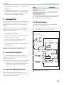
3.2 Wiring Diagram
Figure 1 provides an example of the 4300 and 4400
series toilets wiring specifications.
I
For the 6500 toilet series, refer to the separately
packaged parts list for wiring information.
Flush Switch
(Wall Mounted or Lever)
Water Valve
Cam Switch
2A Fuse or
Circuit Breaker
Motor
BlackBlack
Black
Black
Black
Black
Black
Red
D2
1
2
3
4
5
6
7
8
D1
+12
-12
Add
Water
Flush
Red
Red
3 Conductor
Cable
WhiteWhite
White
Red
Red
1 4300 and 4400 Series Wiring Diagram

5
EN
Full Ceramic Gravity Discharge Toilet General Information
4 Operation
This section has information to help you properly use the
basic features associated with the toilet.
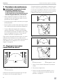
4.1 Using the Flush Touch Panel or
Flush Switch
This section describes how to properly fill the bowl with
water or flush the contents of the bowl, depending on
the type of control you have for the toilet.
OK TO
FLUSH
DO NOT
FLUSH
Dometic Flush Switch
(VFS - 6500 Series Only)
Dometic Flush Switch
(4400 Series Only)
Dometic Flush Touch Panel
(VFSHW - 6500 Series Only)
2 Flush Touch Panel and Flush Switch Operation
1. Press and hold the Add Water indicator to fill the
bowl. Release the indicator once the desired water
level is reached.
2. Press and release the Flush indicator to flush the
toilet.
4.2 Using the Flush Handle
I
4300 Series Only
This section describes how to properly fill the bowl with
water or flush the contents of the bowl, using a flush
handle.
3 4300 Series Flush Handle Operation
1. Li the flush handle to fill the bowl to the desired
water level.
2. Press the flush handle down, then release it to flush
the toilet.
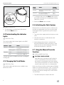
4.3 Using the Bidet Option
I
6500 Series Only
WARNING: FLOOD HAZARD.
Shut the bidet faucet off completely aer use.
Failure to obey this warning could result in death or
serious injury.
This section describes the proper operation of the bidet
function of the toilet.
4 6500 Series Wash Function
1. Turn the handle toward the front of the toilet to
activate the Wash function.

6
EN
General Information Full Ceramic Gravity Discharge Toilet
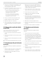
5 6500 Series Bidet Function
2. Turn the handle toward the back of the toilet to
activate the Bidet function.
4.4 Understanding the Indicator
Lights
I
6500 Series Only
This section explains the indicator lights for the 6500
series toilet control.
Indicator Light Status
Power on Steady green Electrical power to the toilet
is activated
Flashing green Flush mode is changing
Tank level Amber Holding tank is 75% full
Red Holding tank is 100% full
1
1
The flush actuation is disabled to prevent overfilling the
holding tank.
4.5 Changing the Flush Modes
I
6500 Series Only
This section explains the flush modes available for the
6500 series toilets.
Flush
mode
Action
Volume
per flush
Normal Adds water to the bowl aer
every flush
1 qt
(0.95 L)
Dry bowl Does not add water to the
bowl aer every flush
1 pt
(0.5 L)
1. To change modes, press the Flush switch or hold
the handle until the power-on light begins flashing
(about five seconds).
2. Release the Flush switch or handle.
4.6 Initializing the Toilet System
Before the first use of the toilet system, or before each
use aer an extended period of non-use, perform the
following procedure to get the toilet system ready for
operation:
1. Turn on the water supply and electrical power to the
toilet.
2. Flush the toilet once to confirm that the toilet
functions as expected.
3. Add holding tank deodorant or treatment into
the bowl and flush the toilet several times to add
additional water into the holding tank (follow the
deodorant manufacturer’s directions).
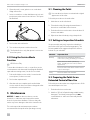
4.7 Using the Manual Override
Function
I
4300 and 4400 Series Only
CAUTION: FLOOD HAZARD.
Shut off the toilet system before performing any
service or maintenance tasks and do not leave
the vehicle for extended periods of time with the
toilet system circuit breaker on. Failure to obey this
caution could result in minor or moderate injury.
In the event of a power failure and emergency flushing is
required, to clean the toilet bowl or seals, or to perform
service or maintenance tasks that require keeping the
flush ball open without running water, use the manual
override feature.
1. Turn off the main power switch to the toilet.

7
EN
Full Ceramic Gravity Discharge Toilet Maintenance
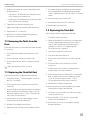
2. Open the small, round, plastic cover on the back
ledge of the toilet.
3. Insert a screwdriver or other thin blunt-end rod, and
push down on the manual override lever. This opens
the flush ball.
6 Manual Override Access
4. Perform the desired function.
5. Turn on the main power switch to the toilet.
I
The flush ball closes only aer power is restored to
the toilet system.
4.8 Using the Service Mode
Function
I
6500 Series Only
To clean the toilet bowl or seals, or to perform service
or maintenance tasks that require keeping the flush ball
open without running water, use the service switch.
1. Push and hold the service switch, located on the
control panel, for three seconds.
2. Perform the required tasks.
3. Aer the tasks are complete, push and hold the
service switch for three seconds to change the toilet
mode back to normal operation.
5 Maintenance
NOTICE: Do not use abrasive cleaners, caustic
chemicals, or lubricants and cleaners that contain
alcohols or petroleum distillates. Failure to obey this
notice may cause damage to the toilet’s internal seals.
This section provides maintenance procedures
recommended to keep the toilet operating correctly.
5.1 Cleaning the Toilet
I
Use non-abrasive cleaners to maintain the original
appearance of the toilet.
Follow this procedure to clean the toilet:
1. Add cleanser to the toilet bowl.
2. Clean the bowl by following the manufacturer’s
instructions on the label of the cleanser.
3. Flush the toilet in normal mode to clear the bowl of
cleanser and debris.
4. Wipe down the toilet body using a damp cloth.
5.2 Setting an Inspection Schedule
Set up a monthly and yearly inspection schedule to
ensure the toilet system is functioning properly. The
following table holds suggested inspection items to
include on your schedule.
Schedule Inspection Task
Monthly Inspect the toilet, plumbing, plumbing
connections, wiring, and wiring connections.
Open and close all of the plumbing
valves, including the seacocks (for marine
applications).
Check the inline water filters and the vented
loops for blockages.
Yearly Check the water valve inlet filter.
5.3 Preparing the Toilet for an
Extended Period of Non-Use
Follow this procedure when not using the boat or RV for
an extended period of time:
1. Flush the toilet in normal mode.
2. Add 4 oz (120 ml) of liquid biodegradable laundry
detergent. The laundry detergent should not
contain bleach or other environmentally harmful
substances.

8
EN
Troubleshooting Full Ceramic Gravity Discharge Toilet
I
If sea water is used for flushing:
– Turn off the power to the sea water pump.
– Pour fresh water directly into the bowl during the
flush cycle.
3. Flush the toilet five times to clear the bowl.
4. Turn off the water supply to the toilet.
5. Flush the toilet without water four times to clear the
remaining water from the system.
6. Turn off the power to the toilet.
7. Completely pump out the holding tank.
8. If the system will be subjected to freezing
temperatures, follow the above procedure, then
proceed to "5.4 Winterizing the Toilet" on page 8.
5.4 Winterizing the Toilet
WARNING: HEALTH HAZARD.
Do not use an automotive-type antifreeze in
fresh-water systems. Failure to obey this warning
could result in death or serious injury.
Before an extended period of non-use in a climate where
temperatures will fall below freezing, the toilet system
should be winterized for storage. Use the following
procedure for winterization of the system:
1. Thoroughly flush the system with fresh water.
2. Drain the potable tank.
3. Empty the holding tank.
4. Add potable-water antifreeze to the fresh-water tank.
I
The amount of antifreeze needed may vary,
depending on the installation.
5. Flush the potable-water antifreeze and water mixture
through the toilet and into the entire plumbing
system. Each installation is different, so amounts may
vary. User discretion is required to assure adequate
protection.
6. Turn off the power to the toilet.
7. Empty the holding tank of any remaining contents.
6 Troubleshooting
This section has information to help you identify and
remedy various functional issues associated with your
toilet. Refer to "7 Service Procedures" on page 11
for additional information. Any service procedures
referenced are intended for emergency purposes.
For additional details on an operational issue, potential
cause, or remedy, contact Customer Service. Refer to
"Customer Support" on page 28.

9
EN
Full Ceramic Gravity Discharge Toilet Troubleshooting
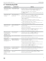
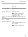
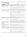
6.1 Troubleshooting Guide
Operational Issue Possible Cause Remedy
The toilet will not flush
and water will not enter
the toilet bowl.
The fuse is blown or the
circuit breaker is tripped.
• Check the toilet fuse or circuit breaker at the DC distribution panel.
• Check for loose/defective wiring between the power source and the
toilet (terminal block pins 5 and 8, for 4300 and 4400 series).
• Check for reverse polarity of the incoming power.
• For 4300 and 4400 series: check for a defective diode D1 at pin 5 of the
terminal block.
The toilet will not flush,
but water enters the
toilet bowl.
There is an electrical or
mechanical failure related to
the flush valve.
• Check for loose/defective wiring between the flush switch and the toilet
(terminal block pins 2 and 3, for 4300 and 4400 series).
• Check for a defective flush switch. Replace if necessary.
• Check for loose flush ball motor wires (terminal block pins 2 and 8, for
4300 and 4400 series).
• Check for a defective flush ball motor. Replace if necessary.
• Check for a motor drive arm failure. Replace if necessary. Refer to section
"7.7 Replacing the Motor Drive Arm" on page 13.
• Check for a drive linkage failure. Replace if necessary. Refer to section
"7.8 Replacing the Drive Linkage" on page 13.
The toilet flushes, but
water does not enter
the toilet bowl.
The water supply is blocked
or there is an electrical
failure.
• Check for a blockage in the water line to the toilet. Remove the line and
clear the blockage.
• Check for a clog in the filter screen at the water valve inlet. Remove the
water line and clear the debris.
• Check for loose or defective wiring between the water valve and toilet
(terminal block pins 1 and 8, for 4300 and 4400 series).
• Check for a defective water valve. Replace if necessary.
Water does not enter
the toilet bowl when
the flush handle or the
wall switch is in the
“Add Water” position.
There is an electrical
connection failure.
• Check for loose or defective wiring between the flush switch and toilet
(terminal block pins 1 and 3, for 4300 and 4400 series).
• Check for a defective flush switch. Replace if necessary.
The water will not shut
off and causes the toilet
bowl to overflow.
There is a water valve failure. • Check for debris in the water valve.
• Check for a defective water valve. Replace if necessary.
The flush ball
constantly cycles
between the open and
closed position.
There is a component
adjustment required or a
component is defective.
• Check the cam switch for adjustment. Refer to section "7.1 Aligning the
Cam Switch/Flush Ball" on page 11.
• Check for a defective cam switch. Replace if necessary.
• Check for defective drive linkage. Replace if necessary. Refer to section
"7.8 Replacing the Drive Linkage" on page 13.
• Check for shorted wiring between the flush switch and toilet (terminal
block pins 2 and 3, for 4300 and 4400 series).
• Check for a defective flush switch. Replace if necessary.
The flush ball opens
slowly or will not open
when the manual flush
lever is pressed.
A component adjustment
is required or there is a
defective component.
• Check for a defective flush spring assembly. Replace if necessary.
• Check for excessive drag between the flush ball and the flush ball seal.
Lubricate the flush ball and seal it with silicone spray.
The flush switch must
be held in the “Flush”
position to close the
flush ball.
There is a defective electrical
component.
• Check for loose or defective wiring (for 4300 and 4400 series, check
between the cam switch and terminal block pins 2, 3, and 6).
• Check for a defective cam switch.

10
EN
Troubleshooting Full Ceramic Gravity Discharge Toilet
Operational Issue Possible Cause Remedy
The flush ball does not
close completely.
A component adjustment
is required or there is a
defective component.
• Check the cam switch for adjustment. Refer to section "7.1 Aligning the
Cam Switch/Flush Ball" on page 11.
• Check for a defective cam switch. Replace if necessary.
• Check that the rotor sha cam is not loose or defective. If defective,
replace the rotor sha cam. Refer to section "7.6 Replacing the Rotor
Sha Cam" on page 13.
• Check for worn drive linkage. Replace if necessary. Refer to section "7.8
Replacing the Drive Linkage" on page 13.
A squeaky noise occurs
when the flush ball is
opening.
Lubrication of the
component(s) is required.
• Check the drive arm/drive linkage joint. Apply lubrication using silicone
grease, if necessary.
• Check if the flush ball and seal needs lubrication. Use silicone spray if
necessary.
Water will not stay in
the bowl and leaks
down through the flush
ball seal.
There is an incomplete seal
between the flush ball and
the rubber seal.
• Check the cam switch for adjustment. Refer to section "7.1 Aligning the
Cam Switch/Flush Ball" on page 11.
• Check if the mounting bolts that hold the base assembly to the ceramic
toilet needs tightening. Tighten to 20–25 in-lb (2.3–2.8 Nm) of torque.
Notice: Excessive tightening of the bolts can damage the toilet.
• Check to see if the flush ball seal is worn and needs replacement. Refer
to section "7.3 Replacing the Flush Ball Seal" on page 12.
• Check for a defective flush ball. Replace if necessary. Refer to section
"7.4 Replacing the Flush Ball" on page 12.
The toilet flushes in
both the “Add Water”
and the “Flush” switch
positions.
There is a defective electrical
component.
• For 4300 and 4400 series: check for a defective diode D2 on terminal
block pins 1 and 2. Replace if necessary.
Water will not enter the
toilet bowl during the
“Flush” cycle.
There is a defective electrical
component or the water may
be turned off.
• For 4300 and 4400 series: check for a defective diode D2 on terminal
block pins 1 and 2. Replace if necessary.
• Confirm the water is turned on and the water valve is open. Turn the
water on, and open the water valve, if applicable.
Water is leaking from
the toilet onto the floor.
There is a loose connection
or a defective component.
• Check for a loose water line connection. Tighten the connection, if
necessary.
• Check for a loose or defective vacuum breaker. Replace if necessary.
• Check for a defective water valve. Replace if necessary.
• Check for a defective ball seal.
• Check if the mounting bolts that hold the base assembly to the ceramic
toilet needs tightening. Tighten to 20–25 in-lb (2.3–2.8 Nm) of torque.
Notice: Excessive tightening of the bolts can damage the toilet.

11
EN
Full Ceramic Gravity Discharge Toilet Troubleshooting
7 Service Procedures
WARNING: ELECTRICAL SHOCK, FIRE,
FLOOD, AND/OR EXPLOSION HAZARD.
Failure to obey the following warnings could
result in death or serious injury:
• Use only Dometic replacement parts and
components that are specifically approved for use
with the appliance.
• This product must be installed and serviced by a
qualified service technician.
• Do not modify this product in any way. Modifi cation
can be extremely hazardous.
• Always disconnect the unit from power before
servicing. Confirm that all electrical power to the unit
has been turned off, and for marine applications,
ensure that seacocks are in the closed or off position.
This section has information to help you service the unit
components, if needed. These service procedures are
intended for emergency purposes. Contact "Customer
Support" on page 28.
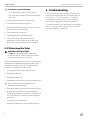
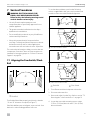
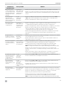
7.1 Aligning the Cam Switch/Flush
Ball
BA
q
7 Correct Cam Switch/Flush Ball Alignment
q
Flush Ball
The flush ball should be properly positioned so that the
“A” and “B” distances are equal (see Figure 7).
If the flush ball becomes misaligned, water can leak from
the bowl or other flushing problems will occur.
To resolve these problems, perform the following
actions as applicable to the over-travel or under-travel
condition of the cam switch/flush ball alignment.
q
w
8 Over-Travel Condition and Fix
q
w
9 Under-Travel Condition and Fix
q
Flush Ball
w
Cam Switch
1. Turn off water and electrical power to the toilet.
2. Disconnect the water line.
3. Remove the toilet from the floor. Refer to section "7.2
Removing the Toilet from the Floor" on page 12.
4. Loosen the cam switch mounting screws using a
3/32 in. (0.25 mm) hex tool and a 1/4 in. (6 mm)
box-end wrench.

12
EN
Troubleshooting Full Ceramic Gravity Discharge Toilet
5. Slide the cam switch up or down depending on the
flush ball position:
– Over-travel: The flush ball leans to the back of the
toilet. Slide the cam switch down.
– Under-travel: The flush ball leans to the front of the
toilet. Slide the cam switch up.
6. Tighten the cam switch mounting screws.
7. Apply electrical power and check the adjustment.
8. Repeat steps 4–7 as necessary.
9. Aer the cam switch and flush ball are properly
positioned, reinstall the toilet.
7.2 Removing the Toilet from the
Floor
Follow this procedure to remove the toilet when needed
for servicing:
1. Turn off the water and the electrical power to the
toilet.
2. Remove the water inlet hose from the toilet.
3. Remove the toilet from the floor and turn it upside-
down.
I
Make sure the power wires are secure.
7.3 Replacing the Flush Ball Seal
Follow this procedure to replace the flush ball seal:
1. Perform the steps in "7.2 Removing the Toilet from
the Floor" on page 12.
2. Disconnect the service switch wires at the in-line
connectors.
3. Remove the three nuts and flat washers securing the
base assembly to the toilet bowl, using a 1/4 in. (6
mm) drive ratchet wrench, 7/16 in. (13 mm) deep-
well socket, and an extension.
4. Pull the check valve out of the sealing grommet
located in the rear of the toilet bowl.
5. Li the base assembly from the toilet.
6. Replace the old seals with a new complete seal kit.
7. Reconnect the base assembly to the toilet with the
new mounting bolts (L-shaped) included with the
seal kit. Tighten the nuts to 20–25 in-lb (2.3–2.8 Nm)
torque.
8. Reconnect the service switch wires.
9. Reattach the water inlet hose to the toilet.
10. Reinstall the toilet to the floor.
7.4 Replacing the Flush Ball
Follow this procedure to replace the flush ball:
1. Turn off the water to the toilet.
2. Open the flush ball in service mode or using manual
override, depending on the toilet series. Refer to
section "4.8 Using the Service Mode Function"
on page 7 or section "4.7 Using the Manual
Override Function" on page 6.
3. Turn off electrical power to the toilet.
4. Disconnect the water inlet hose.
5. Remove the toilet from the floor and turn it upside-
down.
6. Disconnect the service switch wires at in-line
connectors.
7. Pull the check valve out of the sealing grommet
located in the rear of the toilet bowl.
8. Remove the three nuts and flat washers securing the
base assembly to the ceramic toilet bowl, using a
1/4 in. (6 mm) drive ratchet wrench, 7/16 in.
(13 mm) deep-well socket, and an extension.
9. Li the base assembly from the toilet.
10. Remove the bowl seal, the flush-ball seal, and the
retainer plate to expose the flush ball.
11. Loosen the set screw in the rotor sha cam, using a
1/8 in. (4 mm) hex tool.
12. Remove the #8 x 1/4 in. (6 mm) screw and flat
washer from the linkage slot.
13. Remove the four screws securing the mounting
bracket to the base.

13
EN
Full Ceramic Gravity Discharge Toilet Troubleshooting
14. Pull the mounting bracket and the rotor cam off the
base.
15. Rotate the flush ball forward and remove the flush-
ball retaining screw.
16. Replace the flush ball.
17. Reverse the disassembly procedure. Before
reassembling the entire toilet:
– Push the rotor cam all the way onto the rotor sha
and tighten the set screw.
– Lubricate the moving parts with silicone grease.
– Check the cam switch for adjustment. See "7.1
Aligning the Cam Switch/Flush Ball" on page 11.
7.5 Replacing the Rotor Sha
Follow this procedure to replace the rotor sha:
1. Follow the disassembly steps in "7.4 Replacing the
Flush Ball" on page 12.
2. Pull the rotor sha out from inside the base.
3. Lubricate the O-rings on the new sha using silicone
grease.
4. Align the flat section on the rotor sha with the flat
section in the cam.
5. Push the rotor sha cam fully onto the rotor-sha.
Tighten the set screw.
6. Lubricate all moving parts using silicone grease.
7. Reverse the disassembly procedure. Before
attaching the base to the toilet, check the cam switch
for adjustment. See "7.1 Aligning the Cam Switch/
Flush Ball" on page 11.
7.6 Replacing the Rotor Sha Cam
Follow this procedure to replace the rotor sha cam:
1. Follow disassembly steps under "7.4 Replacing the
Flush Ball" on page 12.
2. Remove the linkage pin clip and pin.
3. Attach the new rotor sha cam to the linkage, using
the pin and clip.
4. Lubricate all moving parts using silicone grease.
5. Reverse the disassembly procedure.
6. Reverse the disassembly procedure. Before
attaching the base to the toilet, check the cam switch
for adjustment. See "7.1 Aligning the Cam Switch/
Flush Ball" on page 11.
7.7 Replacing the Motor Drive Arm
Follow this procedure to replace the motor drive arm:
1. Follow the disassembly steps in "7.4 Replacing the
Flush Ball" on page 12.
2. Remove the four motor-mounting screws.
3. Remove the motor from the mounting bracket.
4. Loosen the drive-arm set screw using a 3/32 in.
(0.25 mm) hex tool.
5. Remove the old drive-arm.
6. Install the new drive arm and push it on the motor
sha as far as possible.
7. Tighten the set screw.
8. Lubricate all moving parts using silicone grease.
9. Reverse the disassembly procedure. Before
attaching the base to the toilet, check the cam switch
for adjustment. See "7.1 Aligning the Cam Switch/
Flush Ball" on page 11.
7.8 Replacing the Drive Linkage
Follow this procedure to replace the drive linkage:
1. Follow the disassembly steps in "7.4 Replacing the
Flush Ball" on page 12.
2. Remove the linkage pin clip and pin at the rotor sha
cam.
3. Remove the flush spring retaining screw and washer
from the retaining post.
4. Remove the flush spring from the old linkage.
5. Insert the flush spring to the new linkage
6. Reattach the spring to the retaining post.

14
EN
Disposal Full Ceramic Gravity Discharge Toilet
7. Attach the linkage to the rotor sha cam using the
pin and clip.
8. Lubricate all moving parts using silicone grease.
9. Reverse the disassembly procedure.
8 Disposal
M
Place the packaging material in the appropriate
recycling waste bins, whenever possible. Consult
a local recycling center or specialist dealer for
details about how to dispose of the product in
accordance with all applicable national and local
regulations.
LIMITED WARRANTY
LIMITED WARRANTY AVAILABLE AT WWW.DOMETIC.
COM/WARRANTY.
IF YOU HAVE QUESTIONS, OR TO OBTAIN A COPY
OF THE LIMITED WARRANTY FREE OF CHARGE,
CONTACT:
DOMETIC CORPORATION
SANITATION CUSTOMER SUPPORT CENTER
13128 STATE ROUTE 226
BIG PRAIRIE, OHIO, USA 44611
1-800-321-9886

15
FR
Cuvette de toilette par gravité encéramique Contenu
1 Explication des symboles etconsignes de
sécurité ............................... 16
1.1 Reconnaître les consignes desécurité .....16
1.2 Comprendre les mots-indicateurs ........16
1.3 Directives supplémentaires ..............16
1.4 Messages de sécurité d’ordre général .....16
2 Indication ............................. 17
3 Informations générales ................. 17
3.1 Pièces détachées recommandées ........17
3.2 Diagramme de câblage. . . . . . . . . . . . . . . . . 17
4 Mode d’emploi ........................ 18
4.1 Utilisation du panneau tactile ou de
l’interrupteur de chasse ................18
4.2 Utilisation de la poignée dechasse .......18
4.3 Utilisation de l’option bidet .............18
4.4 Interprétation des voyants ..............19
4.5 Changement de mode de chasse ........19
4.6 Initialisation de la cuvette detoilette ......19
4.7 Utilisation de la fonction de prise en main ..19
4.8 Utilisation de la fonction
Mode Maintenance ...................20
5 Maintenance ..........................20
5.1 Nettoyage de la cuvette detoilette .......20
5.2 Définition d’un calendrier d’inspection ....20
5.3 Préparation de la cuvette de toilette à une
longue période d’inutilisation ...........21
5.4 Préparation hivernale de
la cuvette de toilette ...................21
6 Dépannage ........................... 21
6.1 Guide de dépannage ..................22
7 Procédures de maintenance .............24
7.1 Alignement interrupteur à
came/boule de chasse .................24
7.2 Dépose de la cuvette
de toilette du plancher .................25
7.3 Remplacement du joint de boule de chasse ..
25
7.4 Remplacement de la boule dechasse .....25
7.5 Remplacement de l’arbre du rotor ........26
7.6 Remplacement de la came
de l’arbre du rotor .....................26
7.7 Remplacement du bras d’entraînement
du moteur ...........................26
7.8 Remplacement de
la tringlerie d’entraînement ..............27
8 Élimination ............................ 27
GARANTIE LIMITÉE ........................ 27
Customer Support. . . . . . . . . . . . . . . . . . . . . . . . . 28
Lire attentivement ces instructions. Ces instructions
DOIVENT rester avec ce produit.
Contenu

16
FR
Explication des symboles etconsignes de sécurité Cuvette de toilette par gravité encéramique
1 Explication des symboles
etconsignes de sécurité
Ce manuel contient des consignes de sécurité et des
instructions pour aider l’utilisateur à éliminer ou réduire
le risque d’accidents et de blessures.
1.1 Reconnaître les consignes
desécurité
C’est le symbole d’alerte à la sécurité. Il signale
des risques de blessures physiques. Obéir à tous les
messages de sécurité qui suivent ce symbole pour
éviter les risques de blessures ou de mort.
1.2 Comprendre les mots-indicateurs
Un mot-indicateur identifie les messages de sécurité
et les messages liés aux dégâts matériels, et signale le
degré ou niveau de gravité du danger.
DANGER!
Indique une situation dangereuse qui, si elle n’est
pas évitée, causera la mort ou des blessures graves.
AVERTISSEMENT
Indique une situation dangereuse qui, si elle n’est pas
évitée, peut causer la mort ou des blessures graves.
ATTENTION
Indique une situation dangereuse qui, si elle n’est
pas évitée, peut causer des blessures légères ou
modérées.
NOTICE: Utilisé pour signaler des pratiques non liées
àune blessure physique.
I
Fournit des renseignements additionnels sans
rapport avec des blessures physiques.
1.3 Directives supplémentaires
Pour réduire le risque d’accidents et de blessures,
observer les directives suivantes avant de continuer
àutiliser ou entretenir cet appareil:
• Lire et comprendre toutes les consignes de sécurité
et les instructions pour éviter tout risque de blessure
ou danger de mort.
• Lire et comprendre ces instructions avant d’utiliser ou
d’entretenir ce produit.
• Toute pièce installée en cours de maintenance doit
être conforme à tous les codes locaux ou nationaux
applicables, y compris la toute dernière édition des
normes suivantes:
États-Unis
– ANSI/NFPA70, Code national de l’électricité (CNE)
– ANSI/NFPA 1192, Code des véhicules récréatifs
– Directives ABYC pour les installations marines
Canada
– CSA C22.1, Parties l et ll, Code canadien de
l’électricité
– CSA Z240 RV Series, véhicules récréatifs
1.4 Messages de sécurité d’ordre
général
AVERTISSEMENT: RISQUE DE DÉCHARGE
ÉLECTRIQUE, DE DÉPART DE FEU,
D’INONDATION ET/OU D’EXPLOSION.
Lenon-respect de ces avertissements pourrait
entraîner de graves blessures, voire la mort:
• Utiliser uniquement des pièces et composants de
rechange Dometic spécifiquement approuvés pour
une utilisation avec cet appareil.
• Ce produit doit être installé et entretenu par un agent
technique qualifié.
• Ne pas modifier ce produit d’une quelconque
manière. Une modifi cation peut être extrêmement
dangereuse.
• Avant de commencer une procédure de maintenance
ou d’entretien sur ce produit, s’assurer que
l’alimentation électrique de l’appareil est entièrement
coupée et, pour les applications marines, que les
robinets sont en position fermée ou arrêt.
• Pour les cuvettes de toilette dans les applications
marines raccordées à tout raccord à travers la coque:
toujours fermer les robinets lorsque la cuvette de
toilette n’est pas utilisée (même si le bateau est laissé
sans surveillance pendant une courte période).
• Pour les applications marines, montrer à tous les
passagers comment fermer les vannes en toute
sécurité lorsque la cuvette de toilette n’est pas utilisée.
• Pour les cuvettes de toilette utilisant de l’eau douce
pour la chasse, déconnecter tous les raccordements
à un réseau d’eau sur les côtes ou municipal lorsque
le bateau ou le VR est laissé sans surveillance pendant
une durée quelconque.

17
FR
Cuvette de toilette par gravité encéramique Indication
NOTICE: RISQUE DE DÉGÂTS MATÉRIELS. Respecter
les consignes suivantes, sinon il y aurait risque de
dommages à la cuvette de toilette ou au système:
• Chasser seulement de l’eau, des déchets corporels et
du papier hygiénique à dissolution rapide.
• Ne pas trop remplir la cuve de rétention; cela
pourrait causer des dommages importants au
système sanitaire. Le remplissage excessif de la cuve
de rétention risque de la rompre ou de libérer son
contenu dans la cale ou le VR.
2 Indication
Les cuvettes de toilette séries 4300, 4400 et 6500 sont
conçues pour une utilisation à l’intérieur d’un bateau
ou d’un véhicule récréatif (ci-après appelé «VR») pour
lequel elles sont fournies.
Suivre ces instructions pour garantir le fonctionnement
correct de la cuvette de toilette. Dometic Corporation
n’endosse aucune responsabilité en cas de dommages
dans les cas suivants:
• Assemblage ou branchement incorrect
• Endommagement du produit résultant des influences
mécaniques et d’une tension excessive
• Altérations du produit sans la permission expresse de
Dometic Corporation.
• Utilisation à d’autres fins que celles décrites dans le
manuel d’utilisation
Dometic Corporation se réserve le droit de modifier
l’apparence et les caractéristiques techniques de
l’appareil sans préavis.
3 Informations générales
Cette section apporte des informations de référence
sur les composants, le câblage et les pièces détachées
recommandées à avoir en stock pour la cuvette de toilette.
I
Les images utilisées dans ce document sont
uniquement fournies à titre de référence. Les
composants et leur emplacement peuvent varier
selon le modèle. Les mesures peuvent varier de
±0,38 po (10 mm).
3.1 Pièces détachées recommandées
Lorsqu’un bateau ou un autre véhicule est utilisé dans
des lieux reculés, avoir les pièces détachées suivantes
sous la main pour garantir le fonctionnement continu de
la cuvette de toilette.
Nom Numéro de pièce
Joint de boule de chasse
Pour le numéro de référence,
voir la liste des pièces
emballée séparément.
Boule de chasse
Robinet d’eau à commande
électrique
Bride-vide
I
Pour commander des pièces de rechange, voir
«Customer Support» à la page28 pour les
coordonnées.
3.2 Diagramme de câblage
La Figure 1 montre un exemple des spécifications de
câblage des cuvettes de toilette 4300 et 4400.
I
Pour la série 6500, se référer à la liste des pièces
emballée séparément pour les informations de câblage.
Interrupteur de chasse
(mural ou poignée)
Robinet d’eau
Interrupteur
à came
Fusible ou
coupe-circuit 2A
Moteur
NoirNoir
Noir
Noir
Noir
Noir
Noir
Rouge
D2
1
2
3
4
5
6
7
8
D1
+12
-12
Ajouter
de l’eau
Chasse
Rouge
Rouge
3 Câble
trifilaire
BlancBlanc
Blanc
Rouge
Rouge
1 Diagramme de câblage des séries 4300 et 4400

18
FR
Informations générales Cuvette de toilette par gravité encéramique
4 Mode d’emploi
Cette section contient des informations qui vous
permettront d’utiliser correctement les fonctions de base
associées à la cuvette de toilette.
4.1 Utilisation du panneau tactile ou
de l’interrupteur de chasse
Cette section décrit comment remplir correctement la
cuvette d’eau ou en évacuer le contenu, selon le type de
commande dont vous disposez.
OK TO
FLUSH
DO NOT
FLUSH
Interrupteur de chasse Dometic
(VFS - série 6500 seulement)
Interrupteur de chasse Dometic
(série 4400 seulement)
Panneau tactile de chasse Domectic
(VFSHW - série 6500 seulement)
2 Mode d’emploi du panneau tactile ou de l’interrupteur de chasse
1. Appuyer sur le voyant Add Water pour remplir la
cuvette. Relâcher le voyant une fois le niveau d’eau
souhaité atteint.
2. Appuyer brièvement sur le voyant Flush pour tirer
lachasse.
4.2 Utilisation de la poignée
dechasse
I
Série 4300 seulement
Cette section décrit comment remplir correctement
lacuvette d’eau ou en chasser le contenu, en utilisant
lapoignée de chasse.
3 Mode d’emploi de la poignée de chasse de la série 4300
1. Soulever la poignée de chasse pour remplir la
cuvette jusqu’au niveau d’eau souhaité.
2. Appuyer sur la poignée de chasse, puis la relâcher
pour vider la cuvette.
4.3 Utilisation de l’option bidet
I
Série 6500 seulement
AVERTISSEMENT : RISQUE D’INONDATION.
Fermer complètement le robinet du bidet après
utilisation. Le non-respect de cet avertissement
pourrait entraîner de graves blessures, voire la mort.
Cette section décrit le mode d’emploi correct de la
fonction bidet de la cuvette de toilette.
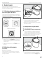
4 Fonction lavage de la série 6500
1. Tourner la poignée vers l’avant de la cuvette de
toilette pour activer la fonction de lavage (Wash).

19
FR
Cuvette de toilette par gravité encéramique Informations générales
5 Fonction bidet de la série 6500
2. Tourner la poignée vers l’arrière de la cuvette de
toilette pour activer la fonction Bidet.
4.4 Interprétation des voyants
I
Série 6500 seulement
Cette section explique les voyants de la commande de
cuvette de toilette série 6500.
Voyant Lampe État
Mise sous
tension
Vert continu L’alimentation électrique
de la cuvette de toilette
estactivée
Vert clignotant Le mode de chasse est en
cours de changement
Niveau
dans la
cuve
Ambre La cuve de rétention est
pleine à 75%
Rouge La cuve de rétention est
pleine à 100%
1
1
L’activation de la chasse est empêchée pour éviter le
remplissage excessif de la cuve de rétention.
4.5 Changement de mode de chasse
I
Série 6500 seulement
Cette section explique les modes de chasse disponibles
pour les cuvettes de toilette série 6500.
Mode de
chasse
Action
Volume par
chasse
Normal Ajoute de l’eau dans la cuvette
après chaque chasse
1 pte (0,95 l)
Cuvette
sèche
N’ajoute pas d’eau dans la
cuvette après chaque chasse
1 chopine
(0,5 l)
1. Pour changer de mode, appuyer sur l’interrupteur
Flush ou appuyer sur la poignée de chasse jusqu’à
ce que le voyant de mise sous tension commence à
clignoter (cinq secondes environ).
2. Relâcher l’interrupteur Flush ou la poignée de
chasse.
4.6 Initialisation de la cuvette
detoilette
Avant la première utilisation du système, ou avant
chaque utilisation après une période d’inutilisation
prolongée, procéder comme suit pour préparer la
cuvette de toilette au fonctionnement:
1. Ouvrir l’arrivée d’eau et rétablir l’électricité à la
cuvette de toilette.
2. Tirer la chasse une fois pour confirmer le
fonctionnement correct de la cuvette de toilette.
3. Ajouter un désodorisant ou un produit de traitement
de la cuve de rétention dans la cuvette et tirer
plusieurs fois la chasse pour ajouter de l’eau dans
la cuve de rétention (suivre le mode d’emploi du
fabricant du désodorisant).
4.7 Utilisation de la fonction de
prise en main
I
Séries 4300 et 4400 seulement
ATTENTION : RISQUE D’INONDATION.
Arrêter le système de cuvette de toilette avant
d’effectuer tout entretien ou toute maintenance
et ne pas laisser le véhicule pendant de longues
périodes avec le coupe-circuit du système de
cuvette de toilette activé. Le non-respect de cette
mise en garde pourrait entraîner des blessures
légères ou modérées.

20
FR
Maintenance Cuvette de toilette par gravité encéramique
Lors d’une panne de courant, si la chasse doit être tirée
d’urgence pour nettoyer la cuvette de toilette ou les joints
ou effectuer une procédure d’entretien ou de maintenance
exigeant le maintien de la boule de chasse ouverte sans
faire couler l’eau, utiliser la fonction de prise en main.
1. Mettre la cuvette de toilette hors tension
àl’interrupteur général.
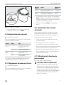
2. Ouvrir le petit couvercle rond en plastique sur le
rebord arrière de la cuvette de toilette.
3. Insérer un tournevis ou une autre tige fine à extrémité
non pointue et appuyer sur le levier de prise en
main. Ceci permet d’ouvrir la boule de chasse.
6 Accès à la fonction de prise en main
4. Effectuer la fonction souhaitée.
5. Mettre la cuvette de toilette sous tension à
l’interrupteur général.
I
La boule de chasse se ferme seulement après le
rétablissement de l’alimentation au système de
cuvette de toilette.
4.8 Utilisation de la fonction Mode
Maintenance
I
Série 6500 seulement
Pour nettoyer la cuvette de toilette ou les joints, ou pour
effectuer des tâches d’entretien ou de maintenance
exigeant de maintenir la boule de chasse ouverte sans
faire couler l’eau, utiliser l’interrupteur Service.
1. Appuyer trois secondes sur l’interrupteur Service,
surle panneau de commande.
2. Effectuer les tâches requises.
3. Une fois les tâches terminées, appuyer sur
l’interrupteur Service pendant trois secondes
pour remettre la cuvette de toilette en mode
defonctionnement normal.
5 Maintenance
NOTICE: Ne pas utiliser de nettoyants abrasifs, de
produits chimiques caustiques ou de lubrifiants et
nettoyants qui contiennent de l’alcool ou des distillats
de pétrole. Respecter cette consigne, sinon il y a risque
d’endommager les joints internes de la cuvette de toilette.
Cette section fournit les procédures d’entretien
recommandées pour maintenir la cuvette de toilette
enétat de fonctionnement correct.
5.1 Nettoyage de la cuvette
detoilette
I
Utiliser des nettoyants non abrasifs pour maintenir
l’aspect initial de la cuvette de toilette.
Suivre cette procédure pour nettoyer la cuvette de toilette:
1. Ajouter du nettoyant à la cuvette de toilette.
2. Nettoyer la cuvette en suivant les instructions du
fabricant sur l’étiquette du nettoyant.
3. Tirer la chasse en mode normal pour vider la cuvette.
4. Passer un chiffon humide sur le corps de la cuvette
de toilette.
5.2 Définition d’un calendrier
d’inspection
Définir un calendrier d’inspection mensuel et annuel
pour garantir le fonctionnement correct du système de
cuvette de toilette. Le tableau suivant contient les points
d’inspection suggérés à inclure au calendrier.
Calendrier Tâche d’inspection
Une fois
parmois
Inspecter la cuvette, la plomberie, les
raccords de plomberie, le câblage et les
branchements de câble.
Ouvrir et fermer toutes les vannes, y compris
les robinets (pour les applications marines).
Vérifier si les filtres à eau intégrés et les
boucles de ventilation ne sont pas bouchés.
Une fois
paran
Vérifier le filtre d’arrivée du robinet d’eau.
La page est en cours de chargement...
La page est en cours de chargement...
La page est en cours de chargement...
La page est en cours de chargement...
La page est en cours de chargement...
La page est en cours de chargement...
La page est en cours de chargement...
La page est en cours de chargement...
-
 1
1
-
 2
2
-
 3
3
-
 4
4
-
 5
5
-
 6
6
-
 7
7
-
 8
8
-
 9
9
-
 10
10
-
 11
11
-
 12
12
-
 13
13
-
 14
14
-
 15
15
-
 16
16
-
 17
17
-
 18
18
-
 19
19
-
 20
20
-
 21
21
-
 22
22
-
 23
23
-
 24
24
-
 25
25
-
 26
26
-
 27
27
-
 28
28


Dometic 4300 4400 6500 Toilets Mode d'emploi
- Taper
- Mode d'emploi
- Ce manuel convient également à
dans d''autres langues
Documents connexes
-
Dometic 4500, 4600, 4700, 4800 Mode d'emploi
-
-
-
-
-
-
-
-
-
Dometic 970, 972, 974, 974MSD975, 975MSD, 976 Mode d'emploi