SportsArt E845-16 Le manuel du propriétaire
- Taper
- Le manuel du propriétaire

1
E845-16 OWNER’S MANUAL CONTENTS
SENZA SERIES DISCLAIMER TERMS ............................................... 2
1. INTRODUCTION .............................................................................. 3
2. SAFETY PRECAUTIONS ................................................................ 4
3. LIST OF PARTS ............................................................................... 9
4. ASSEMBLE THE PRODUCT .......................................................... 11
STEP 1 Install the Frame .................................................................... 11
STEP 2 Install the Glide Rail ............................................................... 16
STEP 3 Install the Pedestal Covers .................................................... 17
STEP 4 Install the Foot Pedals .......................................................... 18
STEP 5 Move the Product into Place ................................................. 20
STEP 6 Level the Product ................................................................... 21
STEP 7 Install the Power Cord ........................................................... 22
STEP 8 TV Terminal and Network ...................................................... 23
STEP 9 Install the TV Cable ............................................................... 24
STEP 10 Beware of Moving Parts ...................................................... 25
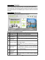
5. UNDERSTAND THE E845 16” SENZA CONSOLE ....................... 26
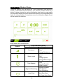
DISPLAY Overview ............................................................................... 26
DISPLAY Keys ...................................................................................... 26
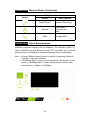
DISPLAY Windows ................................................................................ 26
6. OPERATE THE PRODUCT ............................................................... 27
OPERATION Safety Operating Area ..................................................... 27
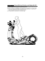
OPERATION Proper Workout Position and Safety Get Off ................... 28
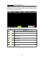
OPERATION Overview .......................................................................... 29
OPERATION Start Screen .................................................................... 29
OPERATION Start Your (GO) Workout .................................................. 30
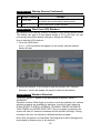
OPERATION Workout Selection ............................................................ 30
OPERATION Workout Programs ........................................................... 31
OPERATION Workout Status ................................................................ 32
OPERATION Select Entertainment ....................................................... 33
OPERATION View Entertainment ......................................................... 35
OPERATION Workout Summary ........................................................... 35
OPERATION Idle Mode ........................................................................ 35
OPERATION Energy Smart Function ................................................... 35
OPERATION Precautions ...................................................................... 35
7. ABOUT HEART RATE DETECTION .................................................. 36
HEART RATE Telemetry ........................................................................ 36
HEART RATE Contact ........................................................................... 36
8. GUIDELINES FOR EXERCISE ......................................................... 37
9. MAINTENANCE ................................................................................ 38
MAINTENANCE Safety Precautions ..................................................... 38
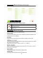
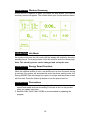
MAINTENANCE Error Messages .......................................................... 38
MAINTENANCE How to Replace a Fuse .............................................. 39
MAINTENANCE Lubrication Procedure ................................................ 40
MAINTENANCE Cleaning the Glide Rails ............................................ 42

E845-16 OWNER’S MANUAL CONTENTS
MAINTENANCE Schedule .................................................................... 43
MAINTENANCE Task List ..................................................................... 44
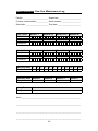
MAINTENANCE One-Year Maintenance Log ....................................... 45
10. ACCESSORIES ............................................................................ 46
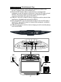
ACCESSORIES Entertainment Cap ..................................................... 47
11. APPENDIXES ................................................................................. 48
APPENDIXES Specications ............................................................... 48
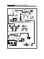
APPENDIXES Electronics Block Diagram ........................................... 49

2
SENZA SERIES DISCLAIMER TERMS
A. Internet function:
A1. This machine provides only a web page browsing method for web page
and video browsing.
A2. For web page videos, we support only Youku and YouTube.
Note: Some videos may not be viewed due to restrictions resulting from
country policies, internal server rewalls, or video formats, etc.
B. IPTV:
This function is not available yet.
C. USB Video:
This function is not available yet.
D. Bluetooth functions:
D1. Bluetooth Music (AVRCP V1.5)
Due to the many varieties of, and rapid changes in, mobile phone models,
failure of a mobile phone to connect indicates that we currently do not
support that phone.
D2. Bluetooth BLE 4.0 Heart Rate Strap
We only support POLAR-compliant Bluetooth BLE 4.0 Heart Rate Straps.
E. TV:
E1. This machine only supports viewing local free TV.
E2. This machine may be affected by the local environment, climate,
equipment, etc., which may cause poor quality in reception and denition.
F. This machine does not support the installation of third-party APPs, which
may affect its operating stability.
G. If any difference in content is found between this manual and the machine,
please contact the local distributor for an electronic manual.
H. USB charger
Supports charging of GOOGLE-certied Android mobile phones, and
Apple iPhone, iPad, iPad air, and iPad mini.
L. CSAFE
This function is not available yet..

3
1. INTRODUCTION
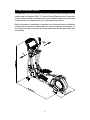
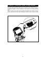
Congratulations on your purchase of one of the nest exercise products on the
market today, the SportsArt E845 16” Senza Console Elliptical trainer. Constructed
of high quality materials and designed for years of reliable usage, this product was
made to become an integral part of your commercial tness venue.
Before this product is assembled or operated, we recommend that you familiarize
yourself with this manual. Understanding the correct assembly and operation of
this product will help ensure that exercisers obtain their tness goals safely and
successfully.
L
R

4
2. SAFETY PRECAUTIONS
Your SportsArt elliptical trainer was designed and built for optimum safety. However
certain precautions apply whenever you use your elliptical trainer.
Please read the entire manual before assembly and operation. Also, please note the
following safety precautions:
● Please read the instructions carefully and install the elliptical trainer as instructed.
● Assemble and operate the elliptical trainer on a solid, level surface. DO NOT use
outdoors or near water.
● Never allow children 12 or younger on or near the elliptical trainer.
● Check the elliptical trainer before every use. Make sure all parts are assembled,
and all fasteners are tightened. DO NOT use the elliptical trainer if the unit is
disassembled in any way.
● Keep your hands away from moving parts.
● Wear proper workout clothing; DO NOT wear loose clothing. DO NOT wear
shoes with leather soles or high heels. Tie all long hair back. DO NOT go barefoot
on this product.
● Be careful when mounting and dismounting the unit.
● The elliptical trainer may or may not stop immediately if an object becomes caught
or impedes normal motion.
● Do not use accessories or parts that are not specically recommended by the
manufacturer (SportsArt). Such parts might cause injuries or cause the unit to fail
and void the warranty. We will not be responsible for any safety issue that arises
due to the misuse of accessories or parts. At the same time, we will terminate the
warranty terms of this equipment.
● Close supervision is necessary when this elliptical trainer is used by, on, or near
children 12 or younger, invalids, or disabled persons.
● Use this elliptical trainer only for its intended use as described in this manual.
● Never operate this elliptical trainer if it has been damaged in any way. If it is not
working properly, or has been dropped or damaged, contact your dealer.
● Keep all air ventilation areas free of blockage.
● Never drop or insert any object into any opening.
● DO NOT operate where aerosol (spray) products are being used or where oxygen
is being administered.
● The general user weight limit for this elliptical trainer is 205kg (450lb). Note that
at resistance level 40 this product meets standards for users of up to 150kg (330lb).

5
2. SAFETY PRECAUTIONS (CONTINUED)
● This elliptical trainer is not intended for use by persons (including children
12 or younger,) with reduced physical, sensory or mental capabilities, or lack
of experience and knowledge, unless they have been given supervision or
instruction concerning use of this elliptical trainer by a person responsible
for their safety.
● Children 12 or younger should be supervised to ensure that they do not
play with the elliptical trainer.
● Maintenance and repair must be performed by trained service personnel
only. Improper maintenance would not only damage the machine, but also
may present a danger to the exerciser.
● Warning that any of the adjustment devices that could interfere with the
user’s movement should not be left projecting.
Caution
If you feel any pain or abnormal sensation, STOP YOUR WORKOUT and
consult your physician immediately. Work within your recommended exer-
cise level. DO NOT work to exhaustion.
Before beginning any exercise program, you should consult with your doc-
tor. It is recommended that you undergo a complete physical examination.
Note: This equipment has been tested and found to comply with the limits
for a Class A digital device, pursuant to part 15 of the FCC Rules. These
limits are designed to provide reasonable protection against harmful in-
terference in a residential installation. This equipment generates, uses,
and can radiate radio frequency energy and, if not installed and used in
accordance with the instructions, may cause harmful interference to radio
communications. However, there is no guarantee that interference will not
occur in a particular installation. If the user desires to correct such interfer-
ence, it is at the user’s own expense.
Warning
Heart rate monitoring systems may be inaccurate. Over exercise may
result in serious injury or death. If you feel faint, stop exercise immediately
and consult a medical physician.

6
2. SAFETY PRECAUTIONS (CONTINUED)
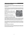
If you are a French speaking person in North America, please place the
following label contained in the owner’s manual on the console as shown.
Customers outside of North America will not receive this French warning
label.
(Note: If there are any other warning labels contained in the owner’s manual,
please place them on the clearly displayed location on the console as well.)

7
2. CONSIGNES DE SÉCURITÉ IMPORTANTES
• Votre vélo SportsArt a été conçu et fabriqué an d’assurer une sécurité
optimale. Cependant certaines précautions s’appliquent chaque fois que
vous utilisez votre vélo de course.
• Lisez entièrement le manuel avant l’assemblage et l’utilisation. Veuillez
aussi noter les consignes de sécurité suivantes:
• Veuillez lire attentivement les instructions et installer le vélo de course
selon les instructions.
• Assemblez et faites fonctionner le vélo sur une surface solide et plane;
NE PAS l’utiliser à l’extérieur ou près de l’eau.
• En aucun cas, ne laissez des enfants à proximité ou sur le vélo.
• Vériez le vélo de course avant chaque utilisation. Assurez-vous que
toutes les pièces sont assemblées, et que tous les éléments de xation
sont serrés. NE PAS utiliser le vélo de course si l’appareil est démonté de
quelque façon.
• Gardez vos mains loin des pièces mobiles.
• Portez des vêtements d’entraînement appropriés; NE PORTEZ PAS de
vêtements amples. NE PORTEZ PAS de chaussures à semelles en cuir
ou à talons hauts. Attachez les cheveux longs. Ne marchez pas pieds nus
sur l’appareil.
• Soyez prudent lors du montage et démontage de l’appareil.
• Le vélo peut s’arrêter ou ne s’arrêter pas immédiatement si quelque
chose obstacle le mouvement.
• NE PAS utiliser d’accessoire non spéciquement recommandé par le
fabricant.
Car cela pourraient provoquer des blessures ou entraîner une
panne de l’appareil.
• Une surveillance étroite est nécessaire quand le vélo est utilisé par ou à
proximité d’enfants, de malades ou de personnes handicapées.
• Utilisez le vélo de course uniquement pour l’usage prévu dans ce man-
uel.
• N’utilisez jamais le vélo de course s’il a été endommagé de quelque
façon que ce soit. S’il ne fonctionne pas correctement, ou s’il est tombé ou
endommagé, contactez votre vendeur.
• Veillez à ce qu’aucun orice de ventilation ne soit obstrué.
• Ne faites jamais tomber ou n’insérez jamais d’objet dans les orices.
• NE PAS l’utiliser là où des produits aérosols (vaporisés) sont utilisés ou
lorsque de l’oxygène est administré.
• La limite de poids de l’utilisateur pour cet vélo est de 205 Kgs (450 lbs).
Remarquez que la résistance de 40 convient jusqu’à 150kgs (330 lbs).
• NE PAS transporter le vélo de course par le cordon d’alimentation et
n’utilisez pas le cordon comme poignée.
• Maintenez le cordon éloigné de toute surface chaude.
• Débranchez l’appareil de la prise avant l’entretien ou la suppression de
toute pièce.
• Pour diminuer le risque de choc électrique, débranchez toujours ce vélo
de course de la prise de courant, immédiatement après utilisation et avant
le nettoyage.

8
2. CONSIGNES DE SÉCURITÉ (SUITE)
Ce vélo n’est pas destiné à être utilisé par des personnes (y compris des enfants)
dont les capacités physiques, sensorielles ou mentales sont réduites ou qui ne
disposent pas de l’expérience ou du savoir nécessaires, sauf si celles-ci ont au
préalable été formées eu égard à l’utilisation de ce vélo par une personne respon-
sable de leur sécurité. Les enfants doivent être encadrés an d’empêcher qu’ils ne
jouent avec le vélo.
ATTENTION
Si vous ressentez une douleur ou si vous avez une sensation anormale,
ARRÊTEZ VOTRE ENTRAÎNEMENT et consultez immédiatement votre médecin.
Entraînez-vous à votre niveau d’exercice recommandé. NE PAS s’entraîner jusqu’à
l’épuisement.
Avant de commencer un programme d’exercice, vous devriez consulter votre
médecin. Il est recommandé de faire un examen physique complet.
Remarque: Ce matériel a été testé et déclaré conforme aux normes des appareils
digitaux de, conformément à la partie 15 du Règlement de la FCC. Ces limites sont
conçues pour offrir une protection raisonnable contre les interférences nuisibles dans
une installation résidentielle. Cet appareil génère, utilise, et peut diffuser des signaux
radioélectriques, et, s’il n’est pas installé et utilisé conformément aux instructions,
peut provoquer des interférences nuisibles aux communications radio. Cependant,
il n’y a aucune garantie que des interférences ne se produiront pas dans une instal-
lation particulière.
Si l’utilisateur désire corriger les interférences, ces corrections seront à la charge de
l’utilisateur.
Dans ce manuel, les mots “gauche” et “droit” sont utilisés en référence aux pièces et
au produit. Comme tels, les mots “gauche” et “droit” font respectivement référence
aux côtés gauche et droit de l’exerciseur. De même pour plus de concision, le
mot est utilisé dans certains cas où des rondelles, des vis et autres matériels sont
associés.
ATTENTION!
Les systèmes de surveillance de la fréquence cardiaque peuvent s’avérer imprécis.
Un entraînement excessif risque de nuire sérieusement à la santé ou d’entraîner la
mort. En cas d’étourdissement, arrêtez immédiatement l’entraînement.
• Un branchement incorrect du connecteur de mise à la terre de
l’équipement risque d’entraîner un choc électrique. En cas de doute sur la
mise à la terre correcte de vélo, faites appel à un technicien ou un élec-
tricien qualié. NE PAS modier la che fournie avec l’elliptique, si elle ne
correspond pas à la prise, faites installer une prise adéquate par un tech-
nicien qualié.
• Les enfants doivent être encadrés an d’empêcher qu’ils ne jouent avec
le vélo.

9
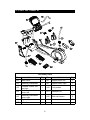
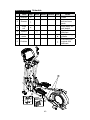
3. LIST OF PARTS
Assembly Parts
No. Name Qty. No. Name Qty.
A1 Main frame 1 A8 Support tube, left 1
A2 Stationary handlebar 1 A9 Support tube, right 1
A3
Pedestal covers, left
and right
1 A10 Foot pedals 1
A4
Stationary handlebar
cover, left
1 A11 Hardware kit 1
A5
Stationary handlebar
cover, right
1 A12 Glide rail covers 2
A6 Right roller cover 2 A13 Power cord 1
A7 Left roller cover 2

10
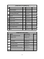
Components in the Hardware Kit
No. Name Qty. Specication Notes
10
Mushroom top inner hex screw 6 M10*P1.5*L25
Serrated washer 6 D20*d10.2*t2.0
11
Secondary guide roller bolt 2 D9.96*L54
Self-lubricating bushing 4
Secondary guide roller 2 D23*L45
12 Stride adjustment linkage cover 2
13
Hex nut 2 M10*P1.5
Stopper 2 Ø30-30
14 Phillips screw 4 M4*P0.7*L12
15 Mushroom top Phillips screw 9 M4*P0.7*L12
16 Phillips screw 2 M5*P0.8*L12
17 Phillips screw 2 M4*P0.7*L8
L-shaped Allen wrench 1 M4
L-shaped Allen wrench 1 M5
T-shaped Allen wrench 1 M6
Hex Phillips wrench 1 13*15
Double open-end wrench 1 14*15
Fuse 1 Slow ADL 1A 110/220V
Components on the Product
No. Name Specication Notes
31 Beveled head hex screw M10*P1.5*L20
32 Phillips screw M4*P0.7*L8
33 Phillips screw M4*P0.7*L14
34
Inner hex screw 5/16"*L2-1/4" half
Flat washer D20*d8*t2.0
35
Mushroom top inner hex screw M8*P1.25*L25
Handlebar washer D18*d8.5*t2
36
Inner hex screw M6*P1.0*L15
Handlebar washer D20*d7*t2
37
Mushroom top inner hex screw M6*P1.0*L15
Flat washer D13*d6*t1
38 Mushroom top inner hex screw M5*P0.8*L16

11
4. ASSEMBLE THE PRODUCT
Follow instructions below to assemble this product. Note that in this manual
the words “left” and “right” are used to refer to the product and its parts. As
such, these designations correspond to the “left” and “right” sides of a person
in position to exercise on this product. Also, for brevity, the word “screws” is
used where screws, washers, and other hardware may be involved.
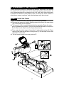
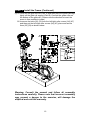
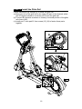
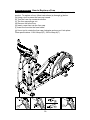
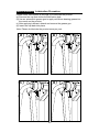
STEP 1 Install the Frame
Please follow instructions (a) through (h) to secure the pedestal.
(a) Remove the upper box and all packing material but leave the main frame
(A1) in the lower box for support.
(b) The screw A (10) is loosely attached before assembly. Raise the main
post or pedestal into position. Secure the pedestal hardware in sequence,
first D (31), then A (10), B and C (10) as shown below.
(c) Then, raise the stride support Assembly (1) and pedal carriage (2). Place
the tip of the food pad surface on the ground (3). Do this step on the other
side of the unit as well.
(d) Tip the frame slightly to access glide rail E.

12
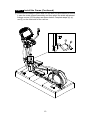
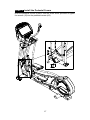
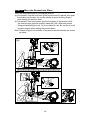
STEP 1 Install the Frame (Continued)
(e) A: Once slip the glide rail into (Part A) and then place the pedal carriage
lightly on the glide rail support (Part B). Connect the guide roller on
the bottom of the glide rail. (Please note the direction to insert the
screw is from outside to inside)
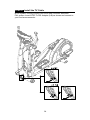
B: Unsecure the bolts (32) (33) from the left/right roller covers (A6) (A7)
and then put the left/right roller covers (A6) (A7) place and secure
them (32) (33) as shown below.
a
b
A
B
Warning: Consult the manual and follow all assembly
instructions carefully. Please note that incorrect assembly
may present a danger to the exercise, will damage the
elliptical and void the warranty.

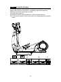
13
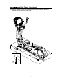
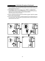
STEP 1 Install the Frame (Continued)
(f) Put the stride linkage in place and use the bolt (34) and washer to secure
it onto the stride support assembly and then press the stride adjustment
linkage covers (12) into place as shown below. Complete steps (d), (e),
and (f) on the other side of the unit too.

14
STEP 1 Install the Frame (Continued)
(g) Secure stopper (13) on the front, bottom of both glide rails and then
remove the unit from the lower box.

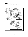
15
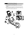
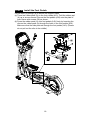
STEP 1 Install the Frame (Continued)
(h) (1) Loosely secure bolts (35) (36) A and B on both support tube (A8)
(A9). At this point, do not tighten these bolts.
(2) With hardware (37) shown in illustration I, secure the stationary
handlebar (A2) at both sides and then tighten bolts (35) (36) at area
A and B.
(3) Secure the stationary handlebar covers (A4) (A5) with screws (14).
When securing the handlebar, make sure direction of screws (14) are
90-degree to the stationary handlebar (A2).

16
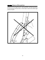
STEP 2 Install the Glide Rail
Follow instructions (a) through (c) to install the glide rail.
(a) Move part (A) of the glide rail to the upper left part of the flywheel within
the 90-degree indication. Hook the part B onto the glide rail.
(b) Turn part B clockwise as shown to a nearly horizontal position of the glide
rail covers (A12).
(c) Install part C onto part B. Use screws (15) (16) to fasten these parts
together.

17
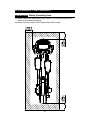
STEP 3 Install the Pedestal Covers
Hold the pedestal covers in place. Use the screw driver provided to tighten
the screws (15) into the pedestal covers (A3).

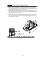
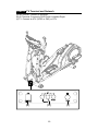
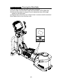
18
STEP 4 Install the Foot Pedals
Follow steps (a) through (b) to secure the support tubes.
(a) There are rubber pads (A) on the foot pedals (A10). Fold the rubber pad
(A) up to access screws. Secure the foot pedals (A10) onto the plate of
main frame with screws (38) as shown.
(b) Press the rubber pads (A) onto foot pedals (A10) firmly by Inserting the
nibs on the rubber pads (A) through the holes in the foot pedals (A10).
Make sure that the nibs protrude through the foot pedals (A10). (Please
do not pull out the nibs in the middle.)

19
STEP 4 Install the Foot Pedals (Details)
Follow instructions (a) through (c) to install the details of the foot pedals.
(a) Make sure the middle nibs on the foot pedals (A10) are firmly placed
into the middle holes on the foot pedals (A10). Pull the nibs through the
foot pedals (A10) until they fit snugly in place.
(b) Secure the front screws (shown as m1) on the foot pedals (A10). Insert
the front nibs into the holes on the foot pedals (A10) (shown as M). Pull
the front nibs in place securely.
(c) Secure the back screws (shown as n1) on the foot pedals (A10). Insert
the nibs into the holes on the foot pedals (A10) (shown as N). Pull the
nibs securely into place.
La page est en cours de chargement...
La page est en cours de chargement...
La page est en cours de chargement...
La page est en cours de chargement...
La page est en cours de chargement...
La page est en cours de chargement...
La page est en cours de chargement...
La page est en cours de chargement...
La page est en cours de chargement...
La page est en cours de chargement...
La page est en cours de chargement...
La page est en cours de chargement...
La page est en cours de chargement...
La page est en cours de chargement...
La page est en cours de chargement...
La page est en cours de chargement...
La page est en cours de chargement...
La page est en cours de chargement...
La page est en cours de chargement...
La page est en cours de chargement...
La page est en cours de chargement...
La page est en cours de chargement...
La page est en cours de chargement...
La page est en cours de chargement...
La page est en cours de chargement...
La page est en cours de chargement...
La page est en cours de chargement...
La page est en cours de chargement...
La page est en cours de chargement...
La page est en cours de chargement...
La page est en cours de chargement...
-
 1
1
-
 2
2
-
 3
3
-
 4
4
-
 5
5
-
 6
6
-
 7
7
-
 8
8
-
 9
9
-
 10
10
-
 11
11
-
 12
12
-
 13
13
-
 14
14
-
 15
15
-
 16
16
-
 17
17
-
 18
18
-
 19
19
-
 20
20
-
 21
21
-
 22
22
-
 23
23
-
 24
24
-
 25
25
-
 26
26
-
 27
27
-
 28
28
-
 29
29
-
 30
30
-
 31
31
-
 32
32
-
 33
33
-
 34
34
-
 35
35
-
 36
36
-
 37
37
-
 38
38
-
 39
39
-
 40
40
-
 41
41
-
 42
42
-
 43
43
-
 44
44
-
 45
45
-
 46
46
-
 47
47
-
 48
48
-
 49
49
-
 50
50
-
 51
51


SportsArt E845-16 Le manuel du propriétaire
- Taper
- Le manuel du propriétaire
dans d''autres langues
- English: SportsArt E845-16 Owner's manual
Documents connexes
-
SportsArt E845-15 Le manuel du propriétaire
-
-
-
-
-
-
-
-
-
