
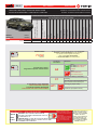
* HOOD PIN HOOD STATUS : THE HOOD PIN SWITCH MUST BE INSTALLED
IF THE VEHICLE CAN BE REMOTE STARTED WITH THE HOOD OPEN,
SET FUNCTION A11 TO OFF.
CONTACT
DE CAPOT
MANDATORY INSTALL | INSTALLATION OBLIGATOIRE Notice: the installation of safety
elements are mandatory. The hood pin
is an essential security element and
must be installed.
Notice: l'installation des éléments de
sécurité est obligatoire. Le contact de
capot est un élément de sécurité
essentiel et doit absolument être
installé.
THIS MODULE MUST BE INSTALLED BY A
QUALIFIED TECHNICIAN. A WRONG
CONNECTION CAN CAUSE PERMANENT
DAMAGE TO THE VEHICLE.
CE MODULE DOIT ÊTRE INSTALLÉ PAR
UN TECHNICIEN QUALIFIÉ, TOUTE
ERREUR DANS LES BRANCHEMENTS
PEUT OCCASIONNER DES DOMMAGES
PERMANENTS AU VÉHICULE.
STATUT DE CAPOT : LE CONTACT DE CAPOT, DOIT ÊTRE INSTALLÉ SI LE
VÉHICULE PEUT DÉMARRER À DISTANCE, LORSQUE LE CAPOT EST OUVERT,
PROGRAMMEZ LA FONCTION A11 À NON.
A11 OFF
NON
ADDENDUM - SUGGESTED WIRING CONFIGURATION
ADDENDA - SCHÉMA DE BRANCHEMENT SUGGÉRÉ
ALL REV.: 20220127 Guide # 95191
Program bypass option:
Programmez l’option du contournement:
UNIT OPTION
OPTION UNITE DESCRIPTION
A5
ON
OUI
AUX.1
Par défaut with OEM alarm
Par défaut avec alarme
d’origine
OFF
NON
AUX.1
without OEM alarm
sans alarme d’origine
FIRMWARE VERSION
VERSION LOGICIELLE To add the rmware version and the options, use the FLASH LINK
UPDATER or FLASH LINK MOBILE tool, sold separately.
Pour ajouter la version logicielle et les options,
utilisez l’outil FLASH LINK UPDATER
ou FLASH LINK MOBILE, vendu séparément.
71.[52]
MINIMUM
C1
OEM Remote status (Lock/Unlock)
monitoring
Suivi des status (Verrouillage/Déverrouil-
lage) de la télécommande d’origine
IF THE VEHICLE IS NOT EQUIPPED
WITH FUNCTIONAL HOOD PIN:
SI LE VÉHICULE N’EST PAS ÉQUIPÉ
D’UN CONTACT DE CAPOT FONCTIONNEL:A11 OFF
NON
Hood trigger (Output Status).
Contact de capot (état de sortie).
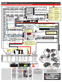
REGULAR, THAR-FOR4 & THAR-FOR1 INSTALLATION
INSTALLATION RÉGULIÈRE, THAR-FOR1 ET THAR-FOR4
“Vehicle functions supported in this diagram (functional if equipped) | Fonctions du véhicule supportées
dans ce diagramme (fonctionnelles si équipé)”
VEHICLE
VEHICULES
YEARS
ANNÉES
Immobilizer bypass
Contournement d’immobilisateur
T-harness available (Sold
separately)
Lock
Unlock
Arm
Disarm
RAP Disable
Parking Lights
Trunk Release
Tachometer
Door Status
Trunk Status
Hood Status*
Hand-Brake Status
Foot-Brake Status
OEM Remote monitoring
FORD
Taurus 40-bits 2008-2012 • • • • • • • • • • • • • • • •
Supported functions & Function programming | Fonctions supportées et programmation des fonctions
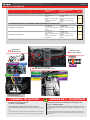
Contents
Supported functions & Function programming | Fonctions supportées et programmation des fonctions 1
Photo & Location | Photos & Emplacements 2
WIRE TO WIRE Connection Diagram | Diagramme de Branchements FIL À FIL 3
THAR-FOR4 - INSTALLATION WIRING | SCHÉMA DE BRANCHEMENT 4
THAR-FOR1 - INSTALLATION WIRING | SCHÉMA DE BRANCHEMENT 5
Key Bypass Programming Procedure | Procédure de Programmation Contournement de Clé 6
Remote starter functionality | Fonctionalité du démarreur à distance 10
Disclaimer | Avertissement 11
Page 1 / 12

This guide may change without notice. See www.fortin.ca for latest version.
Ce guide peut faire l’objet de changement sans préavis. Voir www.fortin.ca pour la récente version.
DESCRIPTION | DESCRIPTION
Parts required (Not
included)
Pièce(s) requise(s) (Non
incluse(s)) PAGE
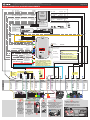
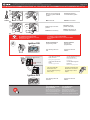
WIRE TO WIRE DIAGRAM | SCHÉMA DE BRANCHEMENTS FIL À FIL
1x 7.5 Amp. fuse
1x fuse
2x 1Amp. Diodes (with OEM
alarm)
1x 1Amp. Diodes (without
OEM alarm)
1x Fusible 7.5 Amp.
1x Fusible
2x Diodes 1 Amp. (avec alarme
d’orgine)
1x Diodes 1 Amp. (sans alarme
d’orgine)
Page 3
THARNESS DIAGRAM | SCHÉMA DE BRANCHEMENTS HARNAIS EN T
THARNESS THAR-FORD4
1x THAR-FOR4
1x 7.5 Amp. fuse
2x 1Amp. Diodes (with OEM
alarm)
1x THAR-FOR4
1x Fusible 7.5 Amp.
2x Diodes 1 Amp. (avec alarme
d’orgine)
Page 4
THARNESS THAR-FORD1
1x THAR-FOR1
1x 7.5 Amp. fuse
2x 1Amp. Diodes (with OEM
alarm)
1x 1Amp. Diodes (without
OEM alarm)
1x THAR-FOR1
1x Fusible 7.5 Amp.
2x Diodes 1 Amp. (avec alarme
d’orgine)
1x Diodes 1 Amp. (sans alarme
d’orgine)
Page 5
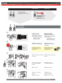
OBD-II connector
Connecteur OBD-II
RX and TX of the module
RX et TX du module
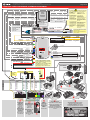
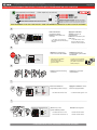
T-HARNESS: 12V BATTERY HARNAIS EN T : 12V BATTERIE
ATTENTION LE COURANT DU 12V PROVENANT DU HARNAIS-EN-T EST
LIMITÉ À 10 AMPÈRES MAXIMUM.
Si les lumières de stationnement (+) requièrent plus de 10 Ampères, branchez
le 12V du démarreur à distance directement à la batterie du véhicule avec le fusible
approprié.
Certains démarreurs à distance NE peuvent PAS être allimentés par le Data-Link.
Dans ce cas, branchez le 12V (avec fusible) du démarreur à distance directement
au harnais-en-T.
ATTENTION THE T-HARNESS CURRENT
IS LIMITED AT 10 AMP MAXIMUM.
If the parking lights (+) require more than 10Amp. connect the
remote-starter's power directly to the vehicles battery with the appropriate
fuse.
Some remote starters can not be powered through Data-Link. In these cases
connect the remote starter's fused 12V power wire directly to the T-Harness.
TAURUS
(+)PARKING
LIGHTS
(-)LOCK
DRIVER
DOOR PIN
(-)UNLOCK
(-)ARM
(-)ARM
BCM Driver side dash board
BCM Tableau de bord côté chauffeur
Ignition barrel
Barillet d'ignition
CAN HIGH
CAN LOW
3
11
(+) ACCESSORY (+) START
(~) TX
(+) IGNITION (+)12V
(~) RX
Photo & Location | Photos & Emplacements
Page 2 / 12

This guide may change without notice. See www.fortin.ca for latest version.
Ce guide peut faire l’objet de changement sans préavis. Voir www.fortin.ca pour la récente version.
Yellow In A1
Purple In A2
Purple/White In A3
Green Out A4
White Out A5
Orange In A6
Orange/Black In A7
Dk.Blue In A8
Red/Blue In A9
Lt.Blue/Black A10
Black Out A11
Pink Out A12
Yellow/Black In A13
Brown/White Out A14
Pink/Black Out A15
Purple/Yellow A16
Green/White A17
Green/Red A18
White/Black A19
Lt.Blue A20
C5 Brown
C4 Gray/Black
C3 Gray
C2 Orange/Brown
C1 Orange/Green
D6 White/Red
D5 White/Blue
D4 White/Green
D3 Yellow/Red
D2 Yellow/Blue
D1 Yellow/Green
AC
D
WIRING CONNECTION | GUIDE DE BRANCHEMENTS
CAN LOW
CAN HIGH
WITH | AVEC DATA-LINK:
ALWAYS REQUIRED
TOUJOURS REQUIS
NOT REQUIRED WITH
DATALINK
NON REQUIS EN
DATA-LINK
B
REMOTE
STARTER
DÉMARREUR
À DISTANCE
WITH | AVEC DATA-LINK:
Direct connection
Branchement directe
HOOD IN RS8
(-)
HAND BRAKE IN RS9
(-)
TRUNK RELEASE
(-) OUT RS11
(+/-) IN RS12
TACHOMETER
F
OOT
B
RAKE
(+)
IN RS13
GROUND OUT WHILE RUNNING
(-) OUT RS14
DOOR
(-) IN RS16
UNLOCK
(-) OUT RS17
LOCK
(-) OUT RS18
A15
A14
A12
A11
A8
A4
A3
A2
Ground | Masse
(-)
RS1
12V BATTERY
RS2 IN
(+)
PARKING LIGHTS
RS4 OUT (+)
ACCESSORY
RS5 OUT (+)
IGNITION
RS6 IN/OUT (+)
STARTER
RS7 OUT (+)
(-) Hood Status
(-) Hand Brake
(-/+) Tachometer
(+) Foot Brake
(+)Start
(-) Ground While Running
(-) Door/Trunk Status
(-) Unlock
(-) Lock
(+) Ignion
A2
A3
A4
A5
A6
A7
A8
A9
A10
A11
A12
A13
A14
A15
A16
A17
A18
A19
A20
C5
C4
C3
C2
C1
D6
D5
D4
D3
D2
D1
A1
D1
D2
D3
D4
C1
C2
C5
A16
A13
A7
A6
26252423222120191817161514
13121110987654321
1 2 3456
71211
1098 13 1615
14
2625
24
23
2221
201918
17
26 27 28 29 30 31
10987
54321
6
26252423222120191817161514
13121110987654321
1 2 3456
71211
1098 13 1615
14
2625
24
23
2221
201918
17
26 27 28 29 30 31
10987
54321
6
4
4
4A
A
B
B
(-)
LOCK (-)
ARM (-)
ARM
(+)PARKING
LIGHT DRIVER
DOOR PIN
1
910
2 3 4 5 7 8
11 12 13 14 15 16
6
11
361
910
2 3 4 5 7 8
11 12 13 14 15 16
6
6
OBD-II
connector
Front view
Connecteur
OBD-II
Vue de face
3
3
CAN
HIGH CAN
LOW
At ignition barrel Transponder
connector Black connector
(4-pins) Back view
Au barillet d'ignition connecteur
du transpondeur. Connecteur
Noir (4-pins) Vue de dos
32
23
At ignition barrel Black ignition
connector (8-pins) Back view
Au barillet d'ignition connecteur
noir d'ignition (8-pins) Vue de dos
1
1
2
235
Ignition barrel
Barillet de l'ignition
1
1
1
1
2
2
TXRX (+) Ignition (+)12V (+)Start
(+) Acces-
sory
110 23456789
192021 17 16 1415
13 12
18
11
25 24 23 2226
TAURUS
Blue/Green
Bleu/Vert
Yellow/Violet
Jaune/Violet
Green/Violet
Vert/Violet
(-)
UNLOCK
Purple/Green
Mauve/Vert
Yellow/Green
Jaune/Vert
CUT
BCM Driver
side dash
board Gray
connector
(10-pins)
Back view
BCM Tableau
de bord côté
chauffeur
Connecteur
Gris (10-pins)
Vue de dos
BCM Driver side
dash board Black
connector
(26-pins)
Back view
BCM Tableau de
bord côté
chauffeur
Connecteur Noir
(26-pins) Vue de
dos
4
21 3456
108
7
9 12 1311
Purple/White
Mauve/Blanc
Brown/Yellow
Brun/Jaune
(-)TRUNK
RELEASE
20 11
3
Violet/Orange
Violet/Orange
Gray/Orange
Gris/Orange
Green/Purple
Vert/Mauve
3
4
11 467
Blue/Red
Bleu/Rouge
Purple/Green
Mauve/Vert
Blue/White
Bleu/Blanc
RS4 A18
A17
RX
Driver Door (Vehicle side)
Driver Door (Con. side)
TX
7.5 AMP.
Fuse
Fusible
OPTIONAL CONNECTION REQUIRED TO ARM THE
FACTORY ALARM WHEN THE DOORS ARE LOCKED
AND RAP CONTROL. I OPTIONNEL
BRANCHEMENTS REQUIS POUR ARMER L'ALARME
D'ORIGINE LORSQUE LES PORTES SONT
VERROUILLÉES ET POUR LE CONTRÔLE DU RAP.
WITHOUT OEM ALARM
SANS ALARM D’ORIGINE
WITH OEM ALARM
AVEC ALARM D’ORIGINE
A5
A19
A19
1AMP. Diode
1AMP. Diode
OR
OU
1Amp
Diode
LOCK
UNLOCK
RS10
RS2/D5RS6/A1
D6 RS8
Fuse
Fusible
A20
A10
C3 C4
(+)Igni�on
(+)12V
Connection required when
programming with two (2) Key.
Branchements requis pour
programmation avec deux (2) clés.
A9
A1
WIRE TO WIRE Connection Diagram | Diagramme de Branchements FIL À FIL
Page 3 / 12

This guide may change without notice. See www.fortin.ca for latest version.
Ce guide peut faire l’objet de changement sans préavis. Voir www.fortin.ca pour la récente version.
Yellow In A1
Purple In A2
Purple/White In A3
Green Out A4
White Out A5
Orange In A6
Orange/Black In A7
Dk.Blue In A8
Red/Blue In A9
Lt.Blue/Black A10
Black Out A11
Pink Out A12
Yellow/Black In A13
Brown/White Out A14
Pink/Black Out A15
Purple/Yellow A16
Green/White A17
Green/Red A18
White/Black A19
Lt.Blue A20
C5 Brown
C4 Gray/Black
C3 Gray
C2 Orange/Brown
C1 Orange/Green
D6 White/Red
D5 White/Blue
D4 White/Green
D3 Yellow/Red
D2 Yellow/Blue
D1 Yellow/Green
AC
D
HOOD IN RS8
(-)
HAND BRAKE IN RS9
(-)
TRUNK RELEASE
(-) OUT RS11
(+/-) IN RS12
TACHOMETER
F
OOT
B
RAKE
(+)
IN RS13
GROUND OUT WHILE RUNNING
(-) OUT RS14
DOOR
(-) IN RS16
UNLOCK
(-) OUT RS17
LOCK
(-) OUT RS18
A15
A14
A12
A11
A8
A4
A3
A2
Ground | Masse
(-)
RS1
12V BATTERY
RS2 IN
(+)
PARKING LIGHTS
RS4 OUT (+)
IGNITION
RS6 IN/OUT (+)
STARTER
RS7 OUT (+)
(-) Hood Status
(-) Hand Brake
(-/+) Tachometer
(+) Foot Brake
(+)Start
(-) Ground While Running
(-) Door/Trunk Status
(-) Unlock
(-) Lock
(+) Ignion
A2
A3
A4
A5
A6
A7
A8
A9
A10
A11
A12
A13
A14
A15
A16
A17
A18
A19
A20
C5
C4
C3
C2
C1
D6
D5
D4
D3
D2
D1
A1
D4
C1
C2
C5
A13
A7
A6
NOT CONNECTED
NE PAS BRANCHER
At ignition barrel Black ignition
connector (8-pins) Back view
Au barillet d'ignition connecteur
noir d'ignition (8-pins) Vue de dos
T-HARNESS - HARNAIS EN T
THAR-FORD4
OBD-II
connector
Front view
Connecteur
OBD-II
Vue de face
4 PINS
6 PINS
At ignition barrel
Transponder connector Black
connector (6-pins) Back view
Au barillet d'ignition
connecteur du transpondeur.
Connecteur Noir (6-pins) Vue
de dos
A
B
26252423222120191817161514
13121110987654321
1 2 3456
71211
1098 13 1615
14
2625
24
23
2221
201918
17
26 27 28 29 30 31
10987
54321
6
26252423222120191817161514
13121110987654321
1 2 3456
71211
1098 13 1615
14
2625
24
23
2221
201918
17
26 27 28 29 30 31
10987
54321
6
4
4
4A
A
B
B
(-)
LOCK (-)
ARM (-)
ARM
(+)PARKING
LIGHT DRIVER
DOOR PIN
110 23456789
192021 17 16 1415
13 12
18
11
25 24 23 2226
TAURUS
Blue/Green
Bleu/Vert
Yellow/Violet
Jaune/Violet
Green/Violet
Vert/Violet
(-)
UNLOCK
Purple/Green
Mauve/Vert
Yellow/Green
Jaune/Vert
CUT
BCM Driver
side dash
board Gray
connector
(10-pins)
Back view
BCM Tableau
de bord côté
chauffeur
Connecteur
Gris (10-pins)
Vue de dos
BCM Driver side
dash board Black
connector
(26-pins)
Back view
BCM Tableau de
bord côté
chauffeur
Connecteur Noir
(26-pins) Vue de
dos
4
21 3456
108
7
9 12 1311
Purple/White
Mauve/Blanc
Brown/Yellow
Brun/Jaune
(-)TRUNK
RELEASE
20
RS4 A18
A17
RX
Driver Door (Vehicle side)
Driver Door (Con. side)
TX
7.5 AMP.
Fuse
Fusible
OPTIONAL CONNECTION REQUIRED TO ARM THE
FACTORY ALARM WHEN THE DOORS ARE LOCKED
AND RAP CONTROL. I OPTIONNEL
BRANCHEMENTS REQUIS POUR ARMER L'ALARME
D'ORIGINE LORSQUE LES PORTES SONT
VERROUILLÉES ET POUR LE CONTRÔLE DU RAP.
WITHOUT OEM ALARM
SANS ALARM D’ORIGINE
WITH OEM ALARM
AVEC ALARM D’ORIGINE
A5
A19
A19
1AMP. Diode
1AMP. Diode
OR
OU
1Amp
Diode
LOCK
UNLOCK
RS10
Yellow
Purple/Yellow
Orange/White
(+)IGNITION
KEY SENSE
IMMO POWER
A9
NOT CONNECTED | NE PAS BRANCHER
5 PIN CONN.
B
Black
Red 12V BATTERY
GROUND
Cut | Coupez
Cut | Coupez
ALWAYS REQUIRED
TOUJOURS REQUIS
NOT REQUIRED WITH
DATALINK
NON REQUIS EN
DATA-LINK
REMOTE
STARTER
DÉMARREUR
À DISTANCE
WITH | AVEC DATA-LINK:
Direct connection
Branchement directe
OR
OU
WITH D2D:
AVEC D2D: WITHOUT
SANS
DATA-LINK:
WITH DATA-LINK:
AVEC DATA-LINK:
Use the DATA-LINK cable supplied
wih the module.
U�lisez le câble DATA-LINK inclus
avec le module.
A1/RS6
NOT CONNECTED | NE PAS BRANCHER
NOT CONNECTED | NE PAS BRANCHER
ATTENTION LE COURANT
DU 12V PROVENANT DU
HARNAIS-EN-T EST
LIMITÉ À 10 AMPÈRES
MAXIMUM.
Si les lumières de
stationnement (+)
requièrent plus de 10
Ampères, branchez le 12V
du démarreur à distance
directement à la batterie du
véhicule avec le fusible
approprié.
Certains démarreurs à
distance NE peuvent PAS
être allimentés par le
Data-Link. Dans ce cas,
branchez le 12V (avec
fusible) du démarreur à
distance directement au
harnais-en-T.
ATTENTION
THE T-HARNESS
CURRENT
IS LIMITED AT 10
AMP MAXIMUM.
If the parking lights
(+) require more than
10Amp. connect the
remote-starter's
power directly to the
vehicles battery with
the appropriate fuse.
Some remote starters
can not be powered
through Data-Link. In
these cases connect
the remote starter's
fused 12V power wire
directly to the
T-Harness.
RS4 A18
A17
RX
Driver Door (Vehicle side)
Driver Door (Con. side)
TX
7.5 AMP.
Fuse
Fusible
OPTIONAL CONNECTION REQUIRED TO ARM THE
FACTORY ALARM WHEN THE DOORS ARE LOCKED
AND RAP CONTROL. I OPTIONNEL
BRANCHEMENTS REQUIS POUR ARMER L'ALARME
D'ORIGINE LORSQUE LES PORTES SONT
VERROUILLÉES ET POUR LE CONTRÔLE DU RAP.
WITHOUT OEM ALARM
SANS ALARM D’ORIGINE
WITH OEM ALARM
AVEC ALARM D’ORIGINE
A5
A19
1AMP. Diode
1AMP. Diode
LOCK
UNLOCK
OR
OU
A19
THAR-FOR4 - INSTALLATION WIRING | SCHÉMA DE BRANCHEMENT
Page 4 / 12

This guide may change without notice. See www.fortin.ca for latest version.
Ce guide peut faire l’objet de changement sans préavis. Voir www.fortin.ca pour la récente version.
Yellow In A1
Purple In A2
Purple/White In A3
Green Out A4
White Out A5
Orange In A6
Orange/Black In A7
Dk.Blue In A8
Red/Blue In A9
Lt.Blue/Black A10
Black Out A11
Pink Out A12
Yellow/Black In A13
Brown/White Out A14
Pink/Black Out A15
Purple/Yellow A16
Green/White A17
Green/Red A18
White/Black A19
Lt.Blue A20
C5 Brown
C4 Gray/Black
C3 Gray
C2 Orange/Brown
C1 Orange/Green
D6 White/Red
D5 White/Blue
D4 White/Green
D3 Yellow/Red
D2 Yellow/Blue
D1 Yellow/Green
AC
D
CAN LOW
CAN HIGH
HOOD IN RS8
(-)
HAND BRAKE IN RS9
(-)
TRUNK RELEASE
(-) OUT RS11
(+/-) IN RS12
TACHOMETER
F
OOT
B
RAKE
(+)
IN RS13
GROUND OUT WHILE RUNNING
(-) OUT RS14
DOOR
(-) IN RS16
UNLOCK
(-) OUT RS17
LOCK
(-) OUT RS18
A15
A14
A12
A11
A8
A4
A3
A2
Ground | Masse
(-)
RS1
12V BATTERY
RS2 IN
(+)
PARKING LIGHTS
RS4 OUT (+)
IGNITION
RS6 IN/OUT (+)
STARTER
RS7 OUT (+)
(-) Hood Status
(-) Hand Brake
(-/+) Tachometer
(+) Foot Brake
(+)Start
(-) Ground While Running
(-) Door/Trunk Status
(-) Unlock
(-) Lock
(+) Ignion
A2
A3
A4
A5
A6
A7
A8
A9
A10
A11
A12
A13
A14
A15
A16
A17
A18
A19
A20
C5
C4
C3
C2
C1
D6
D5
D4
D3
D2
D1
A1
D4
C1
C2
C5
A16
A13
A7
A6
At ignition barrel Black ignition
connector (8-pins) Back view
Au barillet d'ignition connecteur
noir d'ignition (8-pins) Vue de dos
T-HARNESS - HARNAIS EN T
THAR-FORD1
4 PINS
At ignition barrel
Transponder connector Black
connector (4-pins) Back view
Au barillet d'ignition
connecteur du transpondeur.
Connecteur Noir (4-pins) Vue
de dos
26252423222120191817161514
13121110987654321
1 2 3456
71211
1098 13 1615
14
2625
24
23
2221
201918
17
26 27 28 29 30 31
10987
54321
6
26252423222120191817161514
13121110987654321
1 2 3456
71211
1098 13 1615
14
2625
24
23
2221
201918
17
26 27 28 29 30 31
10987
54321
6
4
4
4A
A
B
B
(-)
LOCK (-)
ARM (-)
ARM
(+)PARKING
LIGHT DRIVER
DOOR PIN
1
910
2 3 4 5 7 8
11 12 13 14 15 16
6
11
361
910
2 3 4 5 7 8
11 12 13 14 15 16
6
6
OBD-II
connector
Front view
Connecteur
OBD-II
Vue de face
3
3
CAN
HIGH CAN
LOW
110 23456789
192021 17 16 1415
13 12
18
11
25 24 23 2226
TAURUS
Blue/Green
Bleu/Vert
Yellow/Violet
Jaune/Violet
Green/Violet
Vert/Violet
(-)
UNLOCK
Purple/Green
Mauve/Vert
Yellow/Green
Jaune/Vert
CUT
BCM Driver
side dash
board Gray
connector
(10-pins)
Back view
BCM Tableau
de bord côté
chauffeur
Connecteur
Gris (10-pins)
Vue de dos
BCM Driver side
dash board Black
connector
(26-pins)
Back view
BCM Tableau de
bord côté
chauffeur
Connecteur Noir
(26-pins) Vue de
dos
4
21 3456
108
7
9 12 1311
Purple/White
Mauve/Blanc
Brown/Yellow
Brun/Jaune
(-)TRUNK
RELEASE
20 11
3
Violet/Orange
Violet/Orange
Gray/Orange
Gris/Orange
RS4 A18
A17
RX
Driver Door (Vehicle side)
Driver Door (Con. side)
TX
7.5 AMP.
Fuse
Fusible
OPTIONAL CONNECTION REQUIRED TO ARM THE
FACTORY ALARM WHEN THE DOORS ARE LOCKED
AND RAP CONTROL. I OPTIONNEL
BRANCHEMENTS REQUIS POUR ARMER L'ALARME
D'ORIGINE LORSQUE LES PORTES SONT
VERROUILLÉES ET POUR LE CONTRÔLE DU RAP.
WITHOUT OEM ALARM
SANS ALARM D’ORIGINE
WITH OEM ALARM
AVEC ALARM D’ORIGINE
A5
A19
A19
1AMP. Diode
1AMP. Diode
OR
OU
1Amp
Diode
LOCK
UNLOCK
RS10
Yellow/Black
Lt.Blue/Black
Lt.Blue
Yellow
NOT CONNECTED | NE PAS BRANCHER
(+)IGNITION
A9
NOT CONNECTED | NE PAS BRANCHER
ALWAYS REQUIRED
TOUJOURS REQUIS
NOT REQUIRED WITH
DATALINK
NON REQUIS EN
DATA-LINK
REMOTE
STARTER
DÉMARREUR
À DISTANCE
WITH | AVEC DATA-LINK:
Direct connection
Branchement directe
A1/RS6
B
WITH DATA-LINK:
AVEC DATA-LINK:
WITH D2D:
AVEC D2D:
OR
OU
B2
B1
B4
B3
B2
B1
A10
A20
Cut | Coupez Red
Black
Blue
White
Cut | Coupez
Black
Red 12V Battery
Ground
B4
B3
WITHOUT DATA-LINK:
SANS DATA-LINK:
5 PIN CONN.
Use the connector supplied with the unit.
Utilisez le connecteur fourni avec le module.
20 PIN CONN.
Use the connector supplied
with the unit.
Utilisez le connecteur fourni
avec le module.
ATTENTION LE
COURANT DU 12V
PROVENANT DU
HARNAIS-EN-T EST
LIMITÉ À 10 AMPÈRES
MAXIMUM.
Si les lumières de
stationnement (+)
requièrent plus de 10
Ampères, branchez le
12V du démarreur à
distance directement à la
batterie du véhicule avec
le fusible approprié.
Certains démarreurs à
distance NE peuvent
PAS être allimentés par
le Data-Link. Dans ce
cas, branchez le 12V
(avec fusible) du
démarreur à distance
directement au
harnais-en-T.
ATTENTION
THE T-HARNESS
CURRENT
IS LIMITED AT 10
AMP MAXIMUM.
If the parking lights
(+) require more
than 10Amp.
connect the
remote-starter's
power directly to the
vehicles battery
with the appropriate
fuse.
Some remote
starters can not be
powered through
Data-Link. In these
cases connect the
remote starter's
fused 12V power
wire directly to the
T-Harness.
Fuse Fusible
C3 C4
THAR-FOR1 - INSTALLATION WIRING | SCHÉMA DE BRANCHEMENT
Page 5 / 12

LOCK
ACC ON
PUSH
START
IGN
TURN
ON/RUN
Wait 3 seconds.
LOCK
ACC ON
START
IGN
ON
WAIT
3 SEC.
Attendre 3 secondes.
LOCK
ACC ON
PUSH
START
OFF
TURN
OFF
LOCK
ACC ON
START
PUSHPUSH
REMOVE
KEY
5
KEY#1
CLÉ#1
CONTINUED NEXT PAGE | CONTINUEZ À LA PAGE SUIVANTE
PROGRAMMING PROCEDURE | PROCÉDURE DE PROGRAMMATION
KEY#2
CLÉ#2
KEY#1
CLÉ#1
2 KEY REQUIRED
2 CLÉS REQUISES
Choose between : Choisir entre:
KEY#1
CLÉ#1 KEY#2
CLÉ#2
KEY#1
CLÉ#1
2 key programming.
Programmation avec 2 clés.
DCRYPTOR and 1 key
programming.
Programmation avec
DCRYPTOR et 1 clé.
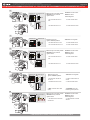
RELEASE
Release the programming
button when the LED is RED.
If the LED is not solid RED
disconnect the 4 Pin
connector (Data-Link) and go
back to step 1.
Insert the required remaining
connectors.
CETTE PROGRAMMATION EST POUR LES
FORD 40BITS
1
2
3
ON RED
ROUGE
Insérez les connecteurs requis
restants.
Relâchez le bouton de
programmation quand la DEL
est ROUGE.
Si le DEL n'est pas ROUGE
solide débranchez le
connecteur 4 pins (Data-Link)
et allez à l'étape 1.
ALL
EOALL
Press and hold the
programming button:
Connect the 4-PIN Data-link
harness (Black connector).
The Blue, Red, Yellow and
Blue & Red LEDs will
alternatively illuminate.
Appuyez et maintenir
enfoncé
le bouton de
programmation:
Branchez le
harnais Data-Link à 4-Broches
(connecteur Noir)
Les DELs Bleue, Rouge,
Jaune et Bleue & Rouge
s'allumeront alternativement.
T
ournez la première
clé fonctionelle à Ignition.
T
urn the first functional key
to the Ignition ON/RUN
position.
T
urn the key to the OFF
position.
Remove
the first key.
T
ournez la clé à la
position
Arrêt (OFF).
Retirez la clé du contact.
x
x
1
1
HOLD
LED may differ depending on the module casing.
L’apparence des DELS peut différer selon le boîtier du module.
4
This guide may change without notice. See www.fortin.ca for latest version.
Ce guide peut faire l’objet de changement sans préavis. Voir www.fortin.ca pour la récente version.
KEY BYPASS PROGRAMMING PROCEDURE 1/2 | PROCÉDURE DE PROGRAMMATION CONTOURNEMENT DE CLÉ 1/2
Key Bypass Programming Procedure | Procédure de Programmation Contournement de Clé
Page 6 / 12

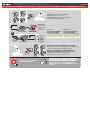
8
Press and release the
programming button.
The vehicle ignition turn
ON.
Pesez et relâchez
le bouton de
programmation.
L'ignition du véhicule
s'allume.
Ignition ON
The RED LED will flash
rapidly 10x times.
The BLUE LED will flash
rapidly.
Key bypass programmed.
CAN-Bus programmed.
La DEL ROUGE clignotera
10x fois rapidement.
La DEL BLEU clignotera
rapidement:
Contournement de clé
programmé.
Réseau CAN programmé.
6
7
5 sec. max
CAUTION The following step must
be completed within 5 seconds.
Otherwise disconnect all connectors
and go back to step 1.
ATTENTION
5 secondes.
débranchez allez
les prochaines étapes doivent être
complétées en moinsde
Si non, tous les connecteurs et
àl'étape 1.
x1
PRESS
Wait 3 seconds. Attendre 3 secondes.
The module is now
programmed.
Le module est
programmé.
Use the remote of the remote
starter or security system to test
all of the supported features to
ensure proper programming.
Testez toutes les fonctions
supportées sur le véhicule avec la
télécommande du démarreur à
distance ou du système de sécurité.
The vehicle ignition will
turn OFF.
L'ignition du véhicule
s'éteins.
Ignition OFF
If the LED is solid RED
disconnect the 4 Pin
connector (Data-Link) and go
back to step 1.
Si le DEL est ROUGE solide
débranchez le connecteur 4
pins (Data-Link) et allez à
l'étape 1.
FLASH 10X
IGNITIONON
FLASH 10X
FLASH
LOCK
ACCON
PUSH
START
IGN
KEY#2
CLÉ#2
LOCK
ACC ON
START
IGN
ON
.
TURN
ON/RUN WAIT
3 SEC
LOCK
ACCO N
PUSH
START
OFF
LOCK
ACC ON
START
PUSHPUSH
F
TURN
OF
REMOVE
KEY
Tournez la deuxième
clé fonctionelle à Ignition.
Turn the second functional
key to the Ignition ON/RUN
position.
Turn
Remove
the key to the OFF
position.
the second key.
Tournez
Retirez
la clé à la
position Arrêt (OFF)
la deuxième clé
du barillet d'alimentation.
This guide may change without notice. See www.fortin.ca for latest version.
Ce guide peut faire l’objet de changement sans préavis. Voir www.fortin.ca pour la récente version.
KEY BYPASS PROGRAMMING PROCEDURE 2/2 | PROCÉDURE DE PROGRAMMATION CONTOURNEMENT DE CLÉ 2/2
Page 7 / 12

x1
HOLD
4
Press and release the
programming button once (1x).
x1
PRESS
Appuyez et relâchez 1 fois le
bouton de programmation.
The RED LED will flash once. La DEL ROUGE clignote 1 fois.
OFF
ON
PRESS X1
OFF
ON
ON
5
The RED LED will turn OFF.
The YELLOW LED will turn on.
La
DEL ROUGE s'éteint.
La DEL JAUNE s'allume.
LOCK
ACC ON
PUSH
START
IGN
ON
IGN IGNITION OFF IGNITION ON
OFF
ON
ON
Tournez la clé à Ignition.
Turn the key to the
Ignition ON/RUN position.
CONTINUED NEXT PAGE | CONTINUEZ À LA PAGE SUIVANTE
1
2
3
The Blue, Yellow, Red and
Blue & Red LEDs will alternatively
illuminate.
Les DELs Bleue, Jaune,
Rouge et Bleue & Rouge
illumineront alternativement.
Release the programming
button when the LED is RED.
Insert the required remaining
connectors. Insérez les connecteurs
requis restants.
Relâchez le bouton de
programmation quand la DEL
est ROUGE.
LED may differ depending on the module casing.
L’apparence des DELS peut différer selon le boîtier du module.
RELEASE
ON RED
ROUGE
Si la DEL n’est pas ROUGE
débranchez le connecteur 4
pins (Data-Link) et allez au
début de l'étape 1.
If the LED is not solid RED
disconnect the 4-Pin
connector (Data-Link) and
go back to step 1.
Press and hold
Insert
the
programming button:
the 4-Pin (Data-Link)
connector.
Appuyez maintenir
enfoncé
Insérez
et
le bouton de
programmation:
le connecteur 4 pins
(Data-Link)
This guide may change without notice. See www.fortin.ca for latest version.
Ce guide peut faire l’objet de changement sans préavis. Voir www.fortin.ca pour la récente version.
DCRYPTOR PROGRAMMING PROCEDURE | PROCÉDURE DE PROGRAMMATION AVEC DCRYPTOR
Parts required (not included) Pièces requises (non incluses)
1x FLASH LINK UPDATER,
1x FLASH LINK MANAGER
1x FLASH LINK MOBILE
1x FLASH LINK MOBILE APP
SOFTWARE | PROGRAMME
Smartphone Android or iOS with Internet connection
(Internet provider charges may apply)
Téléphone Intelligent Android ou iOS avec connection
Internet (des frais du fournisseur Internet peuvent s’appliquer)
OR
OU
Microsoft Windows Computer with Internet connection
Ordinateur Microsoft Windows avec connection Internet
1x1x
BEFORE PROGRAMMING SET THE UNIT OPTIONS AND SAVE. | AVANT LA PROGRAMMATION CONFIGURER LES OPTIONS DE L'UNITÉ ET SAUVEGARDER.
Page 8 / 12

7
The RED LED will turn OFF.
The YELLOW LED will turn on.
La
DEL ROUGE s'éteint.
La DEL JAUNE s'allume.
LOCK
ACC ON
PUSH
START
IGN
ON
IGN IGNITION OFF IGNITION ON
OFF
ON
ON
Tournez la clé à Ignition.
Turn the key to the
Ignition ON/RUN position.
6
LOCK
ACC ON
PUSH
START
OFF
OFF
IGN IGNITION ON IGNITION OFF
ON OFF
The YELLOW LED will turn
OFF.
The RED LED will turn on.
La
DEL JAUNE s'éteint.
La DEL ROUGE s'allume.
ON
8
LOCK
ACC ON
PUSH
START
OFF
OFF
IGN IGNITION ON IGNITION OFF
ON OFF
The YELLOW LED will turn
OFF.
The RED LED will turn on.
La
DEL JAUNE s'éteint.
La DEL ROUGE s'allume.
ON
LOCK
ACCON
PUSH
START
IGN
TURN
ON/RUN
LOCK
ACCO N
PUSH
START
OFF
F
TURN
OF
10
9
The RED and YELLOW LEDs
will alternate.
La DEL ROUGE et JAUNE
alternent.
The YELLOW LED will turn
on and off.
The RED LED will turn OFF.
La
La DEL JAUNE s'allume et
s’éteint.
DEL ROUGE s'éteint.
WAIT, the BLUE LED to flash
rapidly.
ATTENDRE que la DEL
BLEUE clignote rapidement.
Tournez la clé à Ignition.
Turn the key to the
Ignition ON/RUN position.
IGNITIONOFF
ON
ON
FLASH RAPIDLY
OFF
FLASH
IGNITIONOFF IGNITIONON
OFF
ON
ON
CONTINUED NEXT PAGE | CONTINUEZ À LA PAGE SUIVANTE
LOCK
ACC ON
START
PUSHPUSH
REMOVE
KEY
LOCK
ACC ON
START
PUSHPUSH
REMOVE
KEY
LOCK
ACC ON
START
PUSHPUSH
REMOVE
KEY
Turn the key to the OFF position
Remove the key from the
ignition barrel.
.Retirer la clé du
barillet d'ignition.
Fermez la clé de contact.
Turn the key to the OFF position
Remove the key from the
ignition barrel.
.Retirer la clé du
barillet d'ignition.
Fermez la clé de contact.
Turn the key to the OFF position
Remove the key from the
ignition barrel.
.Retirer la clé du
barillet d'ignition.
Fermez la clé de contact.
This guide may change without notice. See www.fortin.ca for latest version.
Ce guide peut faire l’objet de changement sans préavis. Voir www.fortin.ca pour la récente version.
KEY BYPASS PROGRAMMING PROCEDURE 2/3 | PROCÉDURE DE PROGRAMMATION CONTOURNEMENT DE CLÉ 2/3
Page 9 / 12

This guide may change without notice. See www.fortin.ca for latest version.
Ce guide peut faire l’objet de changement sans préavis. Voir www.fortin.ca pour la récente version.
KEY BYPASS PROGRAMMING PROCEDURE 3/3 | PROCÉDURE DE PROGRAMMATION CONTOURNEMENT DE CLÉ 3/3
EVO-ALL
Disconnect all the connectors and after
the Data-Link (4-pins) connector.
Débranchez tous les connecteurs et ensuite
le connecteur Data-Link (4-pins).
*Pièces requises (non incluses)
Use the tool:
FLASH LINK UPDATER or
FLASH LINK MOBILE
to visit the DCryptor menu.
Utilisez l'outil:
FLASH LINK UPDATER ou
FLASH LINK MOBILE
pour visiter le menu DCryptor.
*Parts required (not included)
FLASH LINK UPDATER*
FLASH LINK MOBILE*
FLASH LINK MANAGER*
SOFTWARE | PROGRAMME
Microsoft Windows
Computer with
Internet connection*
Ordinateur Microsoft
Windows avec
connection Internet*
VEHICLE'S OBDII
CONNECTOR
CONNECTEUR OBDII
DU VÉHICULE
OR
OU
Smartphone*
(Internet provider
charges
may apply)
Téléphone
Intelligent*
(des frais du
fournisseur
Internet peuvent
s’appliquer)
AFTER DCRYPTOR PROGRAMMING COMPLETED
Go back to the vehicle and reconnect the 4-Pin (Data-Link)
connector and after, all the remaining connector.
APRÈS LA PROCÉDURE DE PROGRAMMATION
DCRYPTOR COMPLETÉE : retournez au véhicule et
rebranchez le connecteur 4-pins (Data-Link)
et après, tous les connecteurs du EVO-ALL.
EVO-ALL
11
12
13
REMOTE STARTER / ALARM VERIFICATION
PROCEDURE | PROCÉDURE DE VÉRIFICATION
DU DÉMARREUR À DISTANCE / ALARME
Test the remote starter. Remote start the vehicle.
Testez le démarreur à distance. Démarrez le véhicule
à distance.
The module is now programmed.
Le module est programmé.
REMOTE STARTER / ALARM VERIFICATION
PROCEDURE | PROCÉDURE DE VÉRIFICATION
DU DÉMARREUR À DISTANCE / ALARME
Test the remote starter. Remote start the vehicle.
Testez le démarreur à distance. Démarrez le véhicule
à distance.
The module is now programmed.
Le module est programmé.
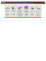
Remote starter functionality | Fonctionalité du démarreur à distance
Page 10 / 12

Remote start the
vehicle.
Démarrez à
distance.
All doors must
be closed.
Toutes les
portes doivent
être fermées.
Start
UNLOCK
Unlock the doors with
the remote-starter
remote or the OEM
remote.
Déverrouillez les portes
avec la télécomande du
démarreur à distance ou
la télécommande
d'origine.
Insert and Turn
the key to the
Ignition ON/RUN
position.
Insérez et
tournez la clé à
la position
"ON/RUN".
The vehicle can
now be put in to
gear and driven.
Vous êtes
maintenant prêt à
embrayer et
prendre la route.
Press
the brake pedal.
Appuyez
sur la pédale de
frein.
ON
TURN
ON/RUN
This guide may change without notice. See www.fortin.ca for latest version.
Ce guide peut faire l’objet de changement sans préavis. Voir www.fortin.ca pour la récente version.
REMOTE STARTER FUNCTIONALITY | FONCTIONNALITÉS DU DÉMARREUR À DISTANCE
Disclaimer | Avertissement
Page 11 / 12

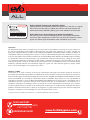
ALL
Service No : 000 102 04 2536
Date: xx-xx
INTERFACE MODULE
Made in Canada
PATENTS PENDING US: 2007-228827-A1
www.fortinbypass.com
HARDWARE VERSION
FIRMWARE VERSION
Module label | Étiquette sur le module
Notice: Updated Firmware and Installation Guides
Updated fi rmware and installation guides are posted on our web site on a regular
basis. We recommend that you update this module to the latest fi rmware and
download the latest installation guide(s) prior to the installation of this product.
Notice: Mise à jour microprogramme et Guides d’installations
Des mises à jour du Firmware (microprogramme) et des guides d’installation
sont mis en ligne régulièrement. Vérifi ez que vous avez bien la dernière version
logiciel et le dernier guide d’installation avant l’installation de ce produit.
WARNING
The information on this sheet is provided on an (as is) basis with no representation or warranty of accuracy whatsoever.
It is the sole responsibility of the installer to check and verify any circuit before connecting to it. Only a computer safe
logic probe or digital multimeter should be used. FORTIN ELECTRONIC SYSTEMS assumes absolutely no liability or
responsibility whatsoever pertaining to the accuracy or currency of the information supplied. The installation in every case
is the sole responsibility of the installer performing the work and FORTIN ELECTRONIC SYSTEMS assumes no liability
or responsibility whatsoever resulting from any type of installation, whether performed properly, improperly or any other
way. Neither the manufacturer or distributor of this module is responsible of damages of any kind indirectly or directly
caused by this module, except for the replacement of this module in case of manufacturing defects. This module must be
installed by qualifi ed technician. The information supplied is a guide only. This instruction guide may change without
notice. Visit www.fortinbypass.com to get the latest version.
MISE EN GARDE
L’information de ce guide est fournie sur la base de représentation (telle quelle) sans aucune garantie de précision et
d’exactitude. Il est de la seule responsabilité de l’installateur de vérifi er tous les fi ls et circuits avant d’effectuer les connexions.
Seuls une sonde logique ou un multimètre digital doivent être utilisés. FORTIN SYSTÈMES ÉLECTRONIQUES n’assume
aucune responsabilité de l’exactitude de l’information fournie. L’installation (dans chaque cas) est la responsabilité de
l’installateur effectuant le travail. FORTIN SYSTÈMES ÉLECTRONIQUES n’assume aucune responsabilité suite à
l’installation, que celle-ci soit bonne, mauvaise ou de n’importe autre type. Ni le manufacturier, ni le distributeur ne se
considèrent responsables des dommages causés ou ayant pu être causés, indirectement ou directement, par ce module,
excepté le remplacement de ce module en cas de défectuosité de fabrication. Ce module doit être installé par un technicien
qualifi é. L’information fournie dans ce guide est une suggestion. Ce guide d’instruction peut faire l’objet de changement
sans préavis. Consultez le www.fortinbypass.com pour voir la plus récente version.
Copyright © 2006-2018, FORTIN AUTO RADIO INC ALL RIGHTS RESERVED PATENT PENDING
TECH SUPPORT
Tél: 514-255-HELP (4357)
1-877-336-7797
ADDENDUM GUIDE WEB UPDATE | MISE À JOUR INTERNET
www.fortinbypass.com
EVO-ALL
Page 12 / 12
-
 1
1
-
 2
2
-
 3
3
-
 4
4
-
 5
5
-
 6
6
-
 7
7
-
 8
8
-
 9
9
-
 10
10
-
 11
11
-
 12
12


dans d''autres langues
- English: Fortin 95191 Installation guide
Documents connexes
-
Fortin 95101 Guide d'installation
-
Fortin 2017 Guide d'installation
-
Fortin 80631 Guide d'installation
-
Fortin EVO 107851 Guide d'installation
-
Fortin 80401 Guide d'installation
-
-
-
Fortin 94911 Guide d'installation
-
Fortin 94791 Guide d'installation
-
Fortin 80671 Guide d'installation