Tetra Edgestrip LED Signage Guide d'installation
- Taper
- Guide d'installation

EdgeStrip
LED Lighting System
Installation Guide
SIGN172 | GE2027-9817
Electrical Requirements
• Limited to use in dry and damp locations.The suitability of rain
enclosures shall be determined if intended for wet location.
• The grounding and bonding of the LED Driver shall be done in
accordance with National Electric Code (NEC) Article 600.
• Follow all National Electric Codes (NEC) and local codes.
Save These Instructions
Use only in the manner intended by the manufacturer.
If you have any questions, contact the manufacturer.
WARNING / AVERTISSEMENT
RISK OF ELECTRIC SHOCK
∙ Turn power off before inspection, installation or removal.
∙ Properly ground power supply enclosure.
RISK OF FIRE
∙ Use only UL approved wire for input/output connections.
Minimum size 18 AWG (0.82mm2)
∙ Follow all NEC and local codes.
∙ Not to be submerged or used in a marine environment.
RISK OF FIRE OR ELECTRIC SHOCK
∙ LED Retrofit Kit installation requires knowledge of
sign electrical systems. If not qualified, do not attempt
installation. Contact a qualified electrician.
∙ Install this kit only in host signs that have been identified in
the installation instructions and where the input rating of
the retrofit kit does not exceed the input rating of the sign.
∙ Installation of this LED retrofit kit may involve drilling or
punching of holes into the structure of the sign. Check
for enclosed wiring and components to avoid damage to
wiring and electrical parts.
∙ Do not make or alter any open holes in an enclosure of
wiring or electrical components during kit installation.
RISQUES DE DÉCHARGES ÉLECTRIQUES
∙ Coupez l’alimentation avant l’inspection, l’installation ou le déplacement.
∙ Assurez-vous de correctement mettre à terre l’alimentation électrique.
RISQUES D’INCENDIE
∙ N’utilisez que des fils approuvés par UL pour les entrées/sorties de connexion. Taille
minimum 18 AWG (0.82mm2)
∙ Respectez tous les codes NEC et codes locaux.
∙ Ne pas submerger ou installer dans un environnement marin.
RISQUE D’INCENDIE OU DE CHOC ÉLECTRIQUE
∙ L’installation de l’équipement de remplacement DEL exige Ia connaissance des
systèmes électriques pour enseignes. Si non qualifié, ne tentez pas d’installation.
Veuillez contacter un électricien qualifié.
∙ Risque d’incendie ou de choc Électrique. Installez cet ensemble seulement dans des
enseignes hôtes qui ont été identifiés dans les instructions d’installation et dont la
capacité d’entrée de l’ensemble ne dépasse pas la capacité d’entrée de l’enseigne.
∙ L’installation de cet équipement de remplacement DEL peut impliquer le perçage
ou le poinçonnage de trous dans la structure du panneau Vérifiez le câblage et
les composants inclus pour éviter d’endommager le câblage et les composants
électriques.
∙ Ne pas faire ou modifier les trous ouverts dans une enceinte de câblage ou de
composants électriques pendant l’installation de cet équipement de remplacement DEL.
GEBI71-2, GEBI50-2, GEBI41-2, GEBI32-2
BEFORE YOU BEGIN
Read these instructions completely and carefully.
2424
Volt
Prepare Electrical Wiring
This device complies with part 15 of the FCC Rules. Operation is subject to the following two conditions: (1) This device may not cause harmful
interference, and (2) this device must accept any interference received, including interference that may cause undesired operation.
Note: This equipment has been tested and found to comply with the limits for a Class A digital device, pursuant to part 15 of the FCC Rules. These limits
are designed to provide reasonable protection against harmful interference when the equipment is operated in a commercial environment. This equipment
generates, uses, and can radiate radio frequency energy and, if not installed and used in accordance with the instruction manual, may cause harmful
interference to radio communications. Operation of this equipment in a residential area is likely to cause harmful interference in which case the user will be
required to correct the interference at his own expense.
This Class [A] RFLD complies with the Canadian standard ICES-005. Ce DEFR de la classe [A] est conforme à la NMB-005 du Canada.

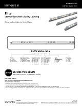
Tetra® EdgeStrip Installation Guide
2
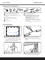
Peel off backing to expose adhesive tape and stick
LED modules into place.
Determine how many modules are required for
your application and cut where necessary.
NOTE: Cuts can be made between any of the LED
modules.
Determine location of where LED modules will
be mounted based on sign dimensions (see
chart). If mounting on bottom of sign, the use of
a riser will be needed (minimum 1/8 in. distance
between bottom surface and module).
Layout LED Modules
Sign
Modules mounted to sides
Use rivets, screws, or silicone to secure each
module within the sign. Use #6 (M3) or #8 (M4)
screws, 1/8-inch (3.2 mm) rivets, or silicone.
Components and Tools Required
UL approved 18 AWG (0.82 mm2) supply wire
UL approved 22-14 AWG (0.33-2.08 mm2) wire
connectors or 22-18 AWG (0.33-0.82 mm2) in-line/IDC
connectors
#6 or #8 (M3 or M4) screws, 1/8 inch
(3.2 mm) rivets or electrical grade silicone
End caps
24 Volt Power Supply
Tetra® EdgeStrip LED modules
Electrical grade RTV silicone.
Example electrical grade RTV silicones include:
• Momentive RTV 6700 Series Silicone Rubber
Adhesive Sealant
• Momentive White Blanc RTV 162 Silicone Rubber
Adhesive Sealant-Electrical Grade
• Dow Corning 3140 - Non-Corrosive Flowable (clear)
• Dow Corning 3145 - Non-Corrosive Nonflowable
(clear or gray)
• Dow Corning RTV 748 Non-Corrosive Sealant-White
TC Measure Point
1
3
2
4
1
1
4
4
5
5
6
6
7
7
2
2
3
3

Tetra® EdgeStrip Installation Guide
3
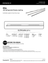
Power
Supply
To LED System
To Power Supply
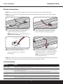
Electrical Connections
NOTE: Refer to the power supply installation instructions for loading and remote mounting information.
NOTE: All electrical connections should be suitably protected from mechanical damage and the environment. Seal all
connections in locations that may be exposed to water with electrical grade RTV silicone.
NOTE: Do not use connectors pre-lled with silicone grease/mineral base protective grease or use silicone grease
to seal connections.
Connect modules using twist-on wire connectors
or in-line (IDC) connectors. Join white wires
together and red striped wires together.
NOTE: Additional supply wire may be necessary to
bridge electrical connections.
Run a wire from the Power Supply and connect
to the first LED module on the strip.
Must be used with a class 2 24 Volt DC
Power Supply. .
Cap all exposed wires with appropriate end
caps or apply electric grade (non-corrosive)
silicone for additional weather protection.
Connect the red stripe wire (+) of the LED
system to the red wire (+) of the power supply.
Connect the white wire (-) of the LED system to
the black or blue wire (-) of the power supply.
NOTE: All electrical connections should be
made within the box sign.
1
1
2
2
Troubleshooting
Symptom Solution
Row of modules
does not light • Check wire connections to power supply to ensure red stripe-to-red and white-to-black or blue connections.
• Check row-to-row polarity connections.
Sign does not light • Check input and output voltage and check power supply input/output connections.
• Check polarity connections.
• Ensure the overall length of the Tetra® LED System does not exceed the maximum load.
Individual modules
do not light • Remove module and replace with another working module.
Modules are dim • Ensure the overall length of the Tetra® LED system does not exceed the maximum load.
• Ensure the length and gauge of the supply wire is equal to or below the recommended remote mounting distance.

Tetra® EdgeStrip Installation Guide
4
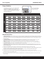
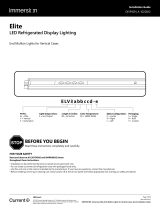
Design Guidelines
All guidelines are based on a 3 in. (76mm) deep
sign for Tetra® EdgeStrip. When installing the
modules, it is typically recommended to install the
modules across the longest distance to allow for
the shortest light throw.
A 2 in. (51 mm) border is
recommended along the
perimeter of the sign.
2 inches
Height
Width
1 . (0.30 m) 2 . (0.61 m) 3 . (0.91 m) 4 . (1.22 m) 5 . (1.52 m) 6 . (1.83 m) 7 . (2.13 m)
1 .
(0.30 m)
EdgeStrip: 1 side
Modules/side: 1
EdgeStrip: 1 side
Modules/side: 2
EdgeStrip: 1 side
Modules/side: 3
EdgeStrip: 1 side
Modules/side: 4
EdgeStrip: 1 side
Modules/side: 5
EdgeStrip: 1 side
Modules/side: 6
EdgeStrip: 1 side
Modules/side: 7
2 .
(0.61 m)
EdgeStrip: 1 side
Modules/side: 2
EdgeStrip: 1 side
Modules/side: 3
EdgeStrip: 1 side
Modules/side: 5
EdgeStrip: 1 side
Modules/side: 6
EdgeStrip: 1 side
Modules/side: 8
EdgeStrip: 1 side
Modules/side: 9
EdgeStrip: 1 side
Modules/side: 11
3 .
(0.91 m)
EdgeStrip: 1 side
Modules/side: 3
EdgeStrip: 1 side
Modules/side: 5
EdgeStrip: 2 sides
Modules/side: 5
EdgeStrip: 2 sides
Modules/side: 6
EdgeStrip: 2 sides
Modules/side: 8
EdgeStrip: 2 sides
Modules/side: 9
EdgeStrip: 2 sides
Modules/side: 11
4 .
(1.22 m)
EdgeStrip: 1 side
Modules/side: 4
EdgeStrip: 1 side
Modules/side: 6
EdgeStrip: 2 sides
Modules/side: 6
EdgeStrip: 4 sides
Modules/side: 6
EdgeStrip: 4 sides
Modules/side: 6-8
EdgeStrip: 4 sides
Modules/side: 6-9
EdgeStrip: 4 sides
Modules/side: 6-11
5 .
(1.52 m)
EdgeStrip: 1 side
Modules/side: 5
EdgeStrip: 1 side
Modules/side: 8
EdgeStrip: 2 sides
Modules/side: 8
EdgeStrip: 4 sides
Modules/side: 6-8
EdgeStrip:
Not Recommended
EdgeStrip:
Not Recommended
EdgeStrip:
Not Recommended
6 .
(1.83 m)
EdgeStrip: 1 side
Modules/side: 6
EdgeStrip: 1 side
Modules/side: 9
EdgeStrip: 2 sides
Modules/side: 9
EdgeStrip: 4 sides
Modules/side: 6-9
EdgeStrip:
Not Recommended
EdgeStrip:
Not Recommended
EdgeStrip:
Not Recommended
7 .
(2.13 m)
EdgeStrip: 1 side
Modules/side: 7
EdgeStrip: 1 side
Modules/side: 11
EdgeStrip: 2 sides
Modules/side: 11
EdgeStrip: 4 sides
Modules/side: 6-11
EdgeStrip:
Not Recommended
EdgeStrip:
Not Recommended
EdgeStrip:
Not Recommended
1. (Existing Signs Only) Prior to installation, survey the site for information regarding power and accessibility inside and outside the
building. Ensure that the branch circuit supplying the existing transformer or ballast will be within the voltage ratings of the new LED
power supply, and have a current rating not exceeding 20A, or that permitted by applicable local, state, or country electrical codes
(whichever is less).
2. (Existing Signs Only) Remove the existing lighting equipment to be replaced, such as neon tubing or fluorescent tubes; and
associated transformers and ballasts. Care should be taken not to break the existing neon or fluorescent tubes.
NOTE: Follow all federal and local regulations when disposing of neon tubing, fluorescent tubes, transformers and ballasts.
3. (Existing Signs Only) If removal of the existing lighting equipment eliminates the disconnect switch, as required by applicable
local, state, or country electrical codes; a new disconnect switch must be installed.
4. (Existing Signs Only) Repair and seal any unused openings in the electrical enclosure. Openings greater than 12.7-mm (1/2-in)
diameter require a metal patch secured by screws or rivets and caulked with non-hardening caulk. Smaller openings may be sealed
with non-hardening caulk.
5. Using the layout guidelines above, determine required number of LED modules required to illuminate the sign.
6. A 24VDC Class 2 Power Supply, as listed below, must be used with this retrofit kit. Determine the number of Power Supplies required
to power the number of LED modules required to illuminate the sign, so as not to overload the Power Supply chosen.
7. Follow the instructions above to properly mount the LED modules.
8. Connect the DC output of the power supply to the LED modules using the Electrical Connections instructions above.
9. Connect the power unit to the supply in accordance with the applicable local, state, and country electrical codes, and the instructions
found in the power supply installation guide.
10. If required, the disconnect switch shall be installed by qualified personnel, in accordance with applicable local, state, and country
electrical codes.
Retrofit Instructions

Tetra® EdgeStrip Installation Guide
This product is intended solely for sign use only. Not intended for general lighting applications.
Conforms to the following standards:
IP66 rated: separate enclosure required for outdoor use, UL damp location rated
III
If you have any questions about these instructions or your specific application, please contact support at [email protected].
For the latest install guides for your product go to: www.LED.com/tetra
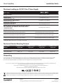
Maximum Loading per 24 VDC Class 2 Power Supply
Power Supply
GEBI71-2, GEBI50-2
GEBI41-2, GEBI32-2
Rating per module 24VDC, 2.52W per module
GEPS24-25U-NA
Load shall not exceed 1.04A 9 modules/9 ft. (2.74 m)
GEPS24D-60U-GLX, *GELP24-60U-GL
Load shall not exceed 2.5A 21 modules / 21 ft. (6.40 m)
GEPS24D-80U, GEPS24W-80
Load shall not exceed 3.3A 30 modules/30 ft. (9.15 m)
GEPS24-100U-GLX, GEPS24D-100U-NA, GEPS24LT-100U-NA,
USVI-100024FBA, USVI-100024FE, GEPS24-100U-GLX2/TT,
**GEPS24V50-100W
Load shall not exceed 4.0A
36 modules/36 ft. (10.97 m)
GEPS24-180U
Load shall not exceed 3.8A per each (of 2) output channels
33 modules/33 ft. (10.06 m) per output channel
66 modules/66 ft. (20.12 m) per power supply
GEPS24-200U-GLX2
Load shall not exceed 4.0A per each (of 2) output channels
36 modules/36 ft. (10.97m) per output channel
72 modules/72 ft. (21.94 m) per power supply
GEPS24-300U-GLX2
Load shall not exceed 4.0A per each (of 3) output channels
36 modules/36ft. (10.98m) per output channel
108 modules/108 ft. (32.94 m) per power supply
Dismantling
At the end of life, the contained LED light source may be cut out using suitable wire cutters, removed from the mounting surface,
then replaced per the cutting and installation instructions above, or dismantled and taken to a communal collecting point for
environmentally friendly disposal in accordance with local regulations by a professional installer.
Electrical products must not be thrown out with domestic waste. They must be taken to a communal collecting point for environmentally friendly
disposal in accordance with local regulations. Contact your local authorities or stockist for advice on recycling. The packaging material is recyclable.
Dispose of the packaging in an environmentally friendly manner and make it available for the recyclable material collection-service.
Power Supply
Wattage
18 AWG/0.82 mm2
Supply Wire
16 AWG/1.31 mm2
Supply Wire
14 AWG/2.08 mm2
Supply Wire
12 AWG/3.31 mm2
Supply Wire
25W 120 ft./36.6 m – – –
60W, 80W, 100W,
180W, 200W, 300W 20 ft./6.1 m 25 ft./7.6 m 35 ft./10.6 m 40 ft./12.1 m
Maximum Remote Mounting Distance
*GELP24-60U-GL minimum load = 8 modules / 8ft. (2.43 m).
**GEPS24V50-100W minimum load = 20 modules / 20 ft (6.10m).
LED.com
© 2023 Current Lighting Solutions, LLC. All rights reserved. Information and specifications subject to change
without notice. All values are design or typical values when measured under laboratory conditions.
Page 5 of 5
(Rev 06/19/23)
SIGN172 | GE2027-9817
-
 1
1
-
 2
2
-
 3
3
-
 4
4
-
 5
5


Tetra Edgestrip LED Signage Guide d'installation
- Taper
- Guide d'installation
dans d''autres langues
Documents connexes
-
Tetra Snap DS Cabinet Signs Guide d'installation
-
-
-
-
-
-
-
-
-
Autres documents
-
GE current Tetra Guide d'installation
-
GE Tetra Guide d'installation
-
GE current GEDS Series Guide d'installation
-
Lumination Contour Series LED Architectural Lighting Guide d'installation
-
 Immersion Elite Gen 2 Vertical Case Center Mullion Lights Guide d'installation
-
 Immersion Elite Gen 2 French Door End Mullion Lights Guide d'installation
-
 Immersion Elite Gen 3 Vertical Case End Mullion Lights Guide d'installation
-
-
 Immersion LED DIsplay Lighting Elite Series Horizontal Guide d'installation
-


