La page est en cours de chargement...

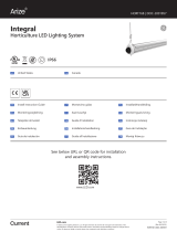
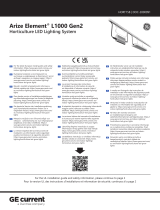
Arize Element® L400
Horticulture LED Lighting System
Installation Guide
HORT110
BEFORE YOU BEGIN / AVANT DE COMMENCER
Read these instructions completely and carefully. Lisez attentivement ces instructions dans leur intégralité.
Save These Instructions
Use only in the manner intended by the manufacturer. If you have any questions, contact the manufacturer.
WARNING / AVERTISSEMENT
RISK OF ELECTRIC SHOCK
• Turn power off before installation, inspection, cleaning or
removal. And follow appropriate lock out/tag out safety
procedure.
• Properly ground electrical enclosure.
• Follow all National Electric Codes (NEC) and local codes.
• This product must be installed in accordance with the
applicable installation code by a person familiar with the
construction and operation of the product and the hazards
involved.
• The installation and associated structures are subject to
approval by the authority having jurisdiction.
• Use only with components identified in this document.
• Suitable for dry, damp, and wet locations; Do not immerse
any component.
• Wear suitable Personal Protective Equipment (PPE) during
installation/maintenance. Highly recommend safety glasses,
helmet and leather glove for luminaire mounting.
• Luminaire design for Greenhouse only.
RISQUE DE CHOC ELECTRIQUE
• Coupez l’alimentation avant l’inspection, l’installation ou la
désinstallation.
• Reliez correctement le boîtier électrique à la mise à la terre.
• Suivre tous les codes électriques locaux applicables.
• Ce produit doit être installé selon le code d’installation
pertinent, par une personne qui connaît bien le produit et
son fonctionnement ainsi que les risques inhérents.
• L’installation et les structures associées sont soumises à
l’approbation des autorités compétentes.
• Utilisez uniquement avec les composants identifiés dans ce
document.
• Convient aux endroits secs, humides et mouillés. Ne doit pas
être immergé.
• Portez les équipements de protection individuelle appropriés
pendant l’installation et la maintenance. L’utilisation de
lunettes de sécurité, d’un casque et des gants de cuir pour le
montage du luminaire est fortement recommandée.
• Luminaire conçu pour serres seulement.
For Commercial or Industrial use only
This device complies with part 15 of the FCC Rules. Operation is subject to the following two conditions: (1) This device may not cause harmful
interference, and (2) this device must accept any interference received, including interference that may cause undesired operation.
NOTE: This equipment has been tested and found to comply with the limits for a Class A digital device, pursuant to part 15 of the FCC Rules. These
limits are designed to provide reasonable protection against harmful interference when the equipment is operated in a commercial environment. This
equipment generates, uses, and can radiate radio frequency energy and, if not installed and used in accordance with the instruction manual, may cause
harmful interference to radio communications. Operation of this equipment in a residential area is likely to cause harmful interference in which case the
user will be required to correct the interference at his own expense.
This Class [A] RFLD complies with the Canadian standard ICES-005. /CeDEFR de la classe [A] est conforme à la NMB-005 du Canada.
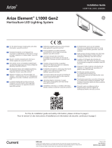
0°C
40°C
Suitable for operation in an ambient temperature
between 32°F (0°C) and 104°F (40°C).
A mechanical ventilation or cooling system is required
to maintain the temperature within the growing
space below 104°F (40°C) when the light module is in
operation.
Opération compatible avec un environnement à
temperature ambiante controlée entre 32°F (0°C) et
104°F (40°C).
l’utilisation d’un système de contrôle de la température
sera nécessaire pour garder la serre sous les 104°F (40°C)
lorsque le luminaire est en function.
LED.com
© 2023 Current Lighting Solutions, LLC. All rights reserved. GE and the GE monogram are trademarks of the
General Electric Company and are used under license. Information and specifications subject to change without
notice. All values are design or typical values when measured under laboratory conditions.
Page 1 of 9
(Rev 06/20/23)
HORT110

Arize Element® L400 Installation Guide
LED.com
© 2023 Current Lighting Solutions, LLC. All rights reserved. GE and the GE monogram are trademarks of the
General Electric Company and are used under license. Information and specifications subject to change
without notice. All values are design or typical values when measured under laboratory conditions.
(Rev 06/20/23)
HORT110
Page 2 of 9
Driver Specifications
SKU Description Weight
Driver Input Ratings
Voltage Current Power Factor
93064969 GEPSC070-210G-ADFNA 1.5kg (3.3 lbs) 120/208/240 VAC, 50/60 Hz 2.5/1.6/1.2 A > 0.9
93117154 GEPSC070-210G-AGJNA 1.5kg (3.3 lbs) 277V-480V 0.9A – 0.5A >0.9
Light Module Specifications
SKU Description Detailed description Weight
LED Module Input Ratings
Voltage Current Power
93067254 GEHR3007M-N120CH-PPR-1 Top Lighting Light module, Purple Type “R” 1.65kg (3.64lbs) 260 VDC 0.7A 182W
93067255 GEHR3007M-N120CH-PPB-1 Top Lighting Light module, Purple Type “B” 255 VDC 0.7A 179W
Inter-Connection Cables Specification
SKU Description Detailed description Weight
93067607 GECA30A14-AA06B Inter-Connection cable 6 feet, UL 0.32kg (0.7 lbs)
93067608 GECA30A14-AA12B Inter-Connection cable 12 feet, UL 0.60kg (1.3 lbs)
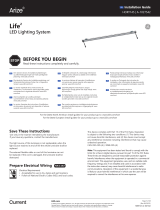
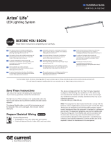
Tools Required
Accessories
SKU Description Components
TBD GEHAK-KN-NA-N0 2 x 1-5/8” square driver brackets and 2 x 1’ support cables
Components Supplied
Top Light module (93067254, 93067255)
Driver (93064969 or 93117154)
Optional: Inter-connection cable (93067607, 93067608)
6
7
8
67 8
+
Compression tool and stop sleeves
Cable cutters
Suspension cable
Tools Required
Turnbuckle
Wire clamp
1
1
2
2
3
3
4 5
5
4

Arize Element® L400 Installation Guide
LED.com
© 2023 Current Lighting Solutions, LLC. All rights reserved. GE and the GE monogram are trademarks of the
General Electric Company and are used under license. Information and specifications subject to change
without notice. All values are design or typical values when measured under laboratory conditions.
(Rev 06/20/23)
HORT110
Page 3 of 9
Important Guidelines
Conseils Importants
• Minimum 4 inch distance from lighting equipment to any combustible material.
• Minimum 4 inch distance between light module and driver or other light module.
• The light module shall be installed lens down with a minimum 5 inch distance to anything below.
•For safe operation, and to maximize the longevity of the luminaire; ensure that the light module and driver are clean and
free of dirt, dust, oil, or any other debris prior to operation. Do not apply any kind of film on the lens or otherwise cover
the driver or light engine in any way.
• Cables shall not be concealed or extended through a wall, floor, ceiling, or other parts of the building structure; located
above a suspended ceiling or dropped ceiling; permanently affixed to the building structure.
• Cables shall be routed so that they are not subject to strain and are protected from physical damage; visible over
their entire length; and used within their rated ampacity as determined for the maximum temperature of the installed
environment specified in the instructions.
• Installer is responsible for driver bank design and construction.
• Driver bank plate shall be made of non-combustible material.
• Installer must select suspension cable able to support 5 times the weight of Light module.
• Maximum cumulative Inter-connection cable length is 24 feet.
• Distance minimale de 4 pouces entre l’équipement d’éclairage et tout matériau combustible.
• Distance minimale de 4 pouces entre le module d’éclairage et le module d’alimentation ou un autre module d’éclairage.
• Le luminaire doit être installé avec l’objectif pointé vers le bas avec une distance minimale de 5 pouces entre le
luminaire et tout objet.
• Pour une opération sécurisée et pour maximiser la longévité du luminaire; S’assurer que le module d’éclairage et le
module d’alimentation sont propres et sans saleté, poussière, huile ou autres débris avant l’opération. Ne pas appliquer
tout type de film sur les lentilles et ne pas couvrir le module d’alimentation ou le module d’éclairage de quelconque
manière.
• Les câbles ne doivent pas être cachés à l’intérieur ou passer à travers un mur, un plancher, un plafond ou d’autres
parties de la structure du bâtiment; ne doivent pas être placés au-dessus d’un plafond suspendu; ne doivent pas faire
partie intégrante de la structure du bâtiment.
• Les câbles doivent être installés de façon à être protégés contre l’étirement et tout autre dommage; être visibles sur
toute leur longueur; utilisés dans la limite de leur capacité électrique, déterminée pour les limites de température de
l’environnement spécifiée dans ce document.
• L’installateur est responsable de la conception, construction et installation du panneau de module d’alimentation.
• La panneau de module d’alimentation doit être fait d’un matériau non-combustible.
• L’installateur doit sélectionner un câble de suspension capable de supporter 5 fois le poids du module d’éclairage.
• La longueur cumulative maximale du câble d’interconnexion est de 24 pieds.
ATTENTION / ATTENTION
• Suspension cable diameter must be between 0.10 inch
(2.5mm) and 0.16 inch (4mm).
• Selection of proper common hardware with good quality is
the responsibility of installer.
• Consider using material having proper strength and
corrosion resistance for the environment.
• Le câble de suspension doit avoir un diamètre entre 0.10
pouce (2.5mm) et 0.16 pouce (4mm).
• La sélection du matériel d’installation de bonne qualité est la
responsabilité de l’installateur.
• Choisissez des matériaux ayant la résistance mécanique et à
la corrosion appropriées pour l’environement.

Arize Element® L400 Installation Guide
LED.com
© 2023 Current Lighting Solutions, LLC. All rights reserved. GE and the GE monogram are trademarks of the
General Electric Company and are used under license. Information and specifications subject to change
without notice. All values are design or typical values when measured under laboratory conditions.
(Rev 06/20/23)
HORT110
Page 4 of 9
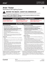
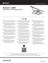
0.078 in. (2.0mm) < Cable diameter < 0.16 in. (4.0mm)
Installation Option A: Hang Luminaires on Horizontal Cable
Turnbuckle
Structural member
Option A Overview
See Page 5 for installation steps.
AC line Top Light Modules
Drivers
Inter-connection cables
Support cable

Arize Element® L400 Installation Guide
LED.com
© 2023 Current Lighting Solutions, LLC. All rights reserved. GE and the GE monogram are trademarks of the
General Electric Company and are used under license. Information and specifications subject to change
without notice. All values are design or typical values when measured under laboratory conditions.
(Rev 06/20/23)
HORT110
Page 5 of 9
Ensure cable is
secured by spring
clips at each end of
the light fixture.
Option A Installation Steps
Loop one end of cable around a structural
member and secure with a stop sleeve.
Secure upper end of support cables to a structural
member at intervals of approximately 16 ft. Secure
lower end to horizontal cable. See Installation
Overview diagram above for reference.
Loosen the turnbuckle and secure it to a structural
member. Secure opposite end of cable to turnbuckle.
Tighten turnbuckle to reduce slack in cable.
Hang light engines on horizontal cable and position them evenly along cable.
Connect light engines to drivers directly or by using inter-connection cables (see next section for details).
Stop sleeve
Structural member
Attach turnbuckle and tighten
Structural
member
Horizontal
cable
Loop one end of cable around a structural
member and secure with a wire clamp.
Wire Clamp
Structural member
Inter-connection cable to driver
ATTENTION / ATTENTION
• Installer is responsible for suspension cable assembly.
• Test cable with at least 5x luminaires weight.
•L’installateur est responsable de l’assemblage du câble de suspension.
• Tester le câble avec au moins 5 fois le poids des luminaires.
1a 1b
2
4
3

Arize Element® L400 Installation Guide
LED.com
© 2023 Current Lighting Solutions, LLC. All rights reserved. GE and the GE monogram are trademarks of the
General Electric Company and are used under license. Information and specifications subject to change
without notice. All values are design or typical values when measured under laboratory conditions.
(Rev 06/20/23)
HORT110
Page 6 of 9
0.10 in. (2.5mm) < Cable diameter < 0.16 in. (4.0mm)
Installation Option B: Hang Luminaires on Vertical Cables
Option B Overview
Structural member
Support cables
AC line Top Light Modules
Drivers
Inter-connection cable
See Page 7 for installation steps.

Arize Element® L400 Installation Guide
LED.com
© 2023 Current Lighting Solutions, LLC. All rights reserved. GE and the GE monogram are trademarks of the
General Electric Company and are used under license. Information and specifications subject to change
without notice. All values are design or typical values when measured under laboratory conditions.
(Rev 06/20/23)
HORT110
Page 7 of 9
Ensure cable is
secured by spring
clips at each end of
the light fixture.
Option B Installation Steps
Loop two cables around a structural member and
secure ends with stop sleeves or wire clamps.
Loop opposite end of cables through top light
hangers and secure with stop sleeves or wire
clamps.
Connect light engines to drivers directly or
by using inter-connection cables (see next
section for details).
Stop sleeve
or
wire clamp
Structural member
Inter-connection cable to driver
ATTENTION / ATTENTION
• Installer is responsible for suspension cable assembly.
• Test cable with at least 5x luminaires weight.
•L’installateur est responsable de l’assemblage du câble de suspension.
• Tester le câble avec au moins 5 fois le poids des luminaires.
1
3
2

Arize Element® L400 Installation Guide
LED.com
© 2023 Current Lighting Solutions, LLC. All rights reserved. GE and the GE monogram are trademarks of the
General Electric Company and are used under license. Information and specifications subject to change
without notice. All values are design or typical values when measured under laboratory conditions.
(Rev 06/20/23)
HORT110
Page 8 of 9
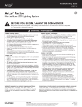
AC line
Driver
Electrical Connections
Connect driver(s) to junction box.
Mate male connector from module with fe-
male connector from DC output of driver.
Connect the green wire to the incoming ground
conductor. Connect the black wire to Line 1
and white wires to the Neutral or Line 2 of the
incoming AC line.
Secure blue lock nut by turning
counterclockwise until tight ensuring water
tight seal and good connection.
Male
Light module
Secure locknut
Driver
Female
AC line
To driver input
Luminaire
Luminaire
6’ or 12’ inter-connection cable
Driver
Driver
Option A
Option B
Option A: Connect driver output directly to
luminaire.
Option B: Connect driver output to luminaire
using inter-connection cable.
1
2
3 4

Arize Element® L400 Installation Guide
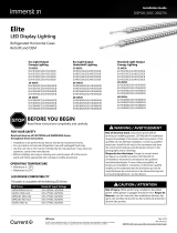
Connection Schematic
Connect the light engine to driver prior to powering the driver. Plug together cables between light engine and
driver. For longer distances between light engine and driver, use an inter-connection cable (6 or 12 feet long) to
complete connection.
Electrical products must not be thrown out with domestic waste. They must be taken to
a communal collecting point for environmentally friendly disposal in accordance with
local regulations. Contact your local authorities or stockist for advice on recycling. The
packaging material is recyclable. Dispose of the packaging in an environmentally friendly
manner and make it available for the recyclable material collection-service.
Conforms to the following standards:
RISK GROUP 2 - CAUTION / ATTENTION - RAYONNEMENT LUMINEUX GROUPE 2
Possibly hazardous optical radiation emitted from this product. Do not stare at operating lamp. May be harmful to the eyes.
Le rayonnement lumineux émis par ce produit est potentiellement dangereux. Ne pas regarder la lumière émise directement
car elle pourrait occasionner des dommages aux yeux.
WARNING / AVERTISSEMENT
RISK OF ELECTRICAL SHOCK: Turn power OFF before inspection, installation or removal.
RISQUE DE CHOC ELECTRIQUE: Coupez l’alimentation avant l’inspection, l’installation ou la désinstallation.
Ambient temperature surrounding each driver must be lower than 104°F (40°C). / La température ambiante autour de chaque module
d’alimentation ne doit pas excéder 104°F (40°C).
Visit LED.com
Call us today! 1-833-733-9243
Email us:
*White = Neutral or Line 2
* * *
Driver Driver Driver Driver
N
3-Phase Y
REPEAT FOR ENTIRE CIRCUIT BALANCING OUT EACH PHASE
3-Phase ∆
L3
L2
L1
Driver Driver
Green
Green
Green
Green
Green
Green
Black
Black
Black
Black
Black
Black
White
White
White
White
White
White
Driver Input Wire
Colors
Black = Line 1
White = Neutral or Line 2
Yellow/Green = Ground
Driver
Light engine
AC line Junction box
Driver bank plate
Use proper circuit
protection level
6’ or 12’ inter-connection cable (Maximum cumulative
length of inter-connection cable is 24 feet)
Plug together
Driver
LED.com
© 2023 Current Lighting Solutions, LLC. All rights reserved. GE and the GE monogram are trademarks of the
General Electric Company and are used under license. Information and specifications subject to change without
notice. All values are design or typical values when measured under laboratory conditions.
Page 9 of 9
(Rev 06/20/23)
HORT110
/