ELICA EAS328SS Manuel utilisateur
- Catégorie
- Hottes
- Taper
- Manuel utilisateur

1
Use, Care, and
Installation Guide
Guide
d’utilisation,
d’entretien et
d’installation
Guía de
instalación, uso y
mantenimiento
READ AND SAVE THESE
INSTRUCTIONS
LISEZ CES
INSTRUCTIONS ET
CONSERVEZ-LES
LEA Y CONSERVE
ESTAS INSTRUCCIONES
LIB0188224
Printed in Mexico
Model: EAS328SS

2
ENGLISH
Contents
Important safety notice ................................................................................................................................................................................................ 3
List of materials ............................................................................................................................................................................................................... 4
Parts supplied ............................................................................................................................................................................................................. 4
Parts not supplied ..................................................................................................................................................................................................... 4
Dimensions and clearances ........................................................................................................................................................................................ 5
Venting requirements ................................................................................................................................................................................................... 5
Ducting options and examples ................................................................................................................................................................................. 6
Electrical requirements ................................................................................................................................................................................................ 6
Installation ......................................................................................................................................................................................................................... 9
Complete the installation ....................................................................................................................................................................................... 10
Description of the hood ............................................................................................................................................................................................... 10
Control ................................................................................................................................................................................................................................ 10
Maintenance ...................................................................................................................................................................................................................... 11
Warranty ............................................................................................................................................................................................................................. 12
APPROVED FOR RESIDENTIAL APPLIANCES
FOR RESIDENTIAL USE ONLY
READ AND SAVE THESE INSTRUCTIONS
PLEASE READ ENTIRE INSTRUCTIONS BEFORE PROCEEDING.
INSTALLATION MUST COMPLY WITH ALL LOCAL CODES.
IMPORTANT: Save these Instructions for the Local Electrical Inspector’s use.
INSTALLER: Please leave these Instructions with this unit for the owner.
OWNER: Please retain these instructions for future reference.
Safety Warning: Turn o power circuit at service panel and lock out panel, before wiring this appliance.
Requirement: 120 V AC, 60 Hz. 15 or 20 A Branch Circuit.
I IMPORTANT SAFETY NOTICE
I CAUTION
FOR GENERAL VENTILATING USE ONLY. DO NOT USE TO
EXHAUST HAZARDOUS OR EXPLOSIVE MATERIALS OR
VAPOURS.
IWARNING
TO REDUCE THE RISK OF FIRE, ELECTRIC SHOCK, OR
INJURY TO PERSONS, OBSERVE THE FOLLOWING:
A. Use this unit only in the manner intended by the
manufacturer. If you have questions, contact the
manufacturer.
B. Before servicing or cleaning the unit, switch power o
at service panel and lock service panel disconnecting
means to prevent power from being switched on
accidentally.
When the service disconnecting means cannot be locked,
securely fasten a prominent warning device, such as a tag,
to the service panel.
C. Installation work and electrical wiring must be done by
qualified person(s) in accordance with all applicable codes
& standards, including fire-rated construction.
D. Sucient air is needed for proper combustion and
exhausting of gases through the flue (Chimney) of fuel
burning equipment to prevent back- drafting.
Follow the heating equipment manufacturers guideline
and safety standards such as those published by the
national fire protection association (NFPA), the american
society for heating, refrigeration and air conditioning
engineers (ASHRAE), and the local code authorities.
E. When cutting or drilling into wall or ceiling, do not
damage electrical wiring and other hidden utilities.
F. Ducted systems must always be vented to the outdoors.
I CAUTION
To reduce risk of fire and to properly exhaust air, be sure to
duct air outside - do not vent exhaust air into spaces within
walls, ceilings, attics, crawl spaces, or garages.
IWARNING
TO REDUCE THE RISK OF FIRE, USE ONLY METAL DUCT
WORK.
Install this hood in accordance with all requirements specified.
IWARNING
To reduce the risk of fire or electric shock, do not use this
hood with any external solid state speed control device.

3
IWARNING
TO REDUCE THE RISK OF A RANGE TOP GREASE FIRE.
a) Never leave surface units unattended at high settings.
Boilovers cause smoking and greasy spillovers that may
ignite. Heat oils slowly on low or medium settings.
b) Always turn hood ON when cooking at high heat or when
flambeing food (I.e. Crepes Suzette, Cherries Jubilee,
Peppercorn Beef Flambe’).
c) Clean ventilating fans frequently. Grease should not be
allowed to accumulate on fan or filter.
d) Use proper pan size. Always use cookware appropriate
for the size of the surface element.
e) Suitable for use in household cooking area.
IWARNING
TO REDUCE THE RISK OF INJURY TO PERSONS, IN THE
EVENT OF A RANGE TOP GREASE FIRE, OBSERVE THE
FOLLOWING:a
a) SMOTHER FLAMES with a close-fitting lid, cookie sheet,
or other metal tray, then turn o the gas burner or the
electric element. BE CAREFUL TO PREVENT BURNS. If the
flames do not go out immediately, EVACUATE AND CALL
THE FIRE DEPARTMENT.
b) NEVER PICK UP A FLAMING PAN - you may be burned.
c) DO NOT USE WATER, including wet dishcloths or towels -
a violent steam explosion will result.
d) Use an extinguisher ONLY if:
1) You know you have a class ABC extinguisher, and
you already know how to operate it.
2) The fire is small and contained in the area where it
started.
3) The fire department is being called.
4) You can fight the fire with your back to an exit.
e) Ducted fans must always be vented to the outdoor.
aBased on “Kitchen Fire Safety Tips” published by NFPA.
OPERATION
Always leave safety grills and filters in place. Without these
components, operating blowers could catch onto hair, fingers
and loose clothing.
The manufacturer declines all responsibility in the event of
failure to observe the instructions given here for installation,
maintenance and suitable use of the product.
The manufacturer further declines all responsibility for injury
due to negligence and the warranty of the unit automatically
expires due to improper maintenance.
I CAUTION
Automatically Operated Device - To Reduce The Risk Of
Injury Disconnect From Power Supply Before Servicing.
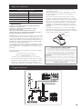
LIST OF MATERIALS
Removing the packaging.
I CAUTION
Remove carton carefully, Wear gloves to protect against sharp edges.
I WARNING
Remove the protective film covering the product before putting into operation.
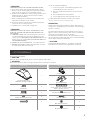
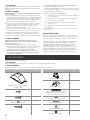
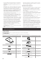
Supplied Part Pieces Supplied Part Pieces
Hood assembly and
LED lamps already installed
1
Hood transition
1
Mounting brackets
2
4.5x13 mm
8Metal spacers (for use when cabinet
depth is greater than 12”)
2
4.2x15 mm 2
3.5x9.5 mm round head screws 6
3.5x9.5 mm flat head screws 4
Torx #10 adapter 1
4.2x19 mm 8
Ø 6.4x18 mm washers
8
Ø 4.2x12 mm washers
8

4
Parts no supplied
Tools/Materials required
• Level
• Drill
• .1” (3.0 mm) drill bit
• Pencil
• Pliers
• Tape measure or ruler
• Caulking gun and weatherproof caulking compound
• Flat-blade screwdriver
• Phillips screwdriver
• Saber or keyhole saw
• Metal snips
• Vent clamps
Parts needed
• 6” (15.2 cm) round metal vent system
IMPORTANT: Observe all governing codes and ordinances.
Have a qualified technician install the range hood. It is the
installer’s responsibility to comply with installation clearances
specified on the model/serial rating plate.
Range hood location should be away from strong draft areas,
such as windows, doors, and strong heating vents.
Cabinet opening dimensions that are shown must be used.
Given dimensions provide minimum clearance. Consult your
cooktop/ range manufacturer installation instructions before
making any cutouts.
Grounded electrical outlet is required.
See “Electrical Requirements” section.
The range hood is factory set for vented installations through
the roof or wall. For non-vented (recirculating) installations
see “Non- Vented (recirculating) Installation Through the
Soffit/Cabinet” in the “Prepare Location” section.
Recirculation Kit Part is available from your dealer or an autho-
rized parts distributor. All openings in ceiling and wall where
range hood will be installed must be sealed.
For mobile home installations
The installation of this range hood must conform to the
Manufactured Home Construction Safety Standards, Title 24
CFR, Part 328 (formerly the Federal Standard for Mobile Home
Construction and Safety, title 24, HUD, Part 280) or when such
standard is not applicable, the standard for Manufactured
Home Installation 1982 (Manufactured Home Sites, Communi-
ties and Setups) ANSI A225.1/NFPA 501A, or latest edition, or
with local codes.
†®TORX is a registered trademark of Saturn Fasteners, Inc.
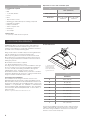
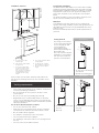
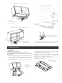
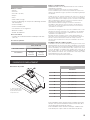
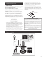
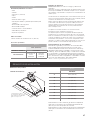
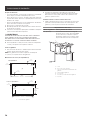
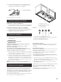
Product dimensions
I* - Metallic spacers
Spacers has to be
installed and used
when cabinet depth
is greater than 12”.
E
A
B
C
F
G
H
D
I*
I*
Model
EAS328SS
A28.2” (71.8 cm)
B26” (66 cm)
C1.1” (2.9 cm)
D10.7” (27.3 cm)
E9.5” (24.2 cm)
F0.3” (.95 cm)
G14.5” (37 cm)
H6” (15.2 cm)
I* 0.5” (1.27 cm)
For gas range installation: Mount this hood so that the bottom
edge is at minimum 30”(76.2 cm) above the cooking surface.
For electric range installation: mount this hood so that the
bottom is not less than 24”(61 cm).
Optional accessories and consumable parts
KIT # Part
28.5” (72.39 cm)
Carbon Filter Kit KIT0184665
Hood Liner Up to 30” width
KIT02773
Up to 36” width
KIT02774
LOCATION REQUIREMENTS

5
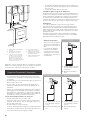
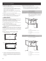
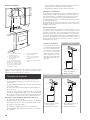
Installation clearances
E
A
B
C
F
D
A. 12” (30.5 cm) min. upper
cabinet height
B. 29.4”(74.8 cm) cabinet width
for 28.5” hood
C. 24” (61 cm) minimum from
the electric cooking surface,
and 30” (76.2x cm) on gas
stove. 36” (91.4 cm) maximum
suggested from the base of
the cabinet to the cooking
surface
D. 12.2” (31 cm) minimum cabinet
opening depth*
E. 15” (38.1 cm) min. clearance
upper cabinet to countertop
F. 36” (91.4 cm) base cabinet
height
Note: for 28.5” hoods, a 36.7” (93.3cm) wide cabinet can
also be used, checking in later steps, the orientation of the
brackets.
• Vent system must terminate to the outdoors, except for no
vented (recirculating) installations.
• Do not terminate the vent system in an attic or other
enclosed area.
• Do not use a 4” (10.2 cm) laundry-type wall cap.
• Rigid metal vent is recommended. Plastic or metal foil
vent is not recommended. The length of vent system and
number of elbows should be kept to a minimum to provide
ecient performance.
For the most ecient and quiet operation:
• Use no more than three 90° elbows.
• Make sure there is a minimum of 24” (61 cm) of straight
vent between the elbows if more than 1 elbow is used.
• Do not install 2 elbows together.
• Use clamps to seal all joints in the vent system.
• The vent system must have a damper.
• Use caulking to seal exterior wall or roof opening around
the cap.
• The size of the vent should be uniform.
Cold weather installations
An additional back draft damper non return valve should be
installed to minimize backward cold air flow and a thermal
break should be installed to minimize conduction of outside
temperatures as part of the vent system. The damper non
return valve should be on the cold air side of the thermal
break.
The break should be as close as possible to where the vent
system enters the heated portion of the house.
Makeup air
Local building codes may require the use of makeup air
systems when using ventilation systems with greater than spe-
cified CFM of air movement. The specified CFM varies from
locale to locale.
Consult your HVAC professional for specific requirements in
your area.
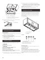
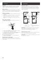
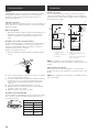
Venting methods Recirculating
This range hood is factory
set for venting through the
roof or through the wall.
You can apply the
recirculating venting
method by purchasing the
Recirculation Kit.
The vent system needed for
installation is not included.
A 6” (15.2 cm) round vent
system is recommended.
A
B
A. 6” (15.2 cm) vent through
the cabinet
B. Round recirculating grid
Roof venting Wall venting
A
B
A. 6” (15.2 cm) vent through
the roof
B. Roof cap
A
B
A. 6” (15.2 cm) vent through
the wall
B. Wall cap
Venting requirements

6
I WARNING
PLUG INTO A GROUNDED 3 PRONG OUTLET.
DO NOT REMOVE GROUND PRONG.
DO NOT USE AN ADAPTER.
DO NOT USE AN EXTENSION CORD.
FAILURE TO FOLLOW THESE INSTRUCTIONS CAN RESULT
IN DEATH, FIRE, OR ELECTRICAL SHOCK.
IMPORTANT: The range hood must be electrically grounded in
accordance with local codes and ordinances, or in the absence
of local codes, with the National Electrical Code, ANSI/NFPA
70 (latest edition) or Canadian Electrical Code, CSA C22.1
No. 0-M91 (latest edition).
If codes permit and a separate ground wire is used, it is
recommended that a qualified electrical installer determine
that the ground path is adequate.
A copy of the above code standards can be obtained from:
National Fire Protection Association
1 Batterymarch Park
Quincy, MA 02169-7471
CSA International
8501 East Pleasant Valley Road
Cleveland, Ohio 44131-5575
• A 120 volt, 60 Hz, AC only, 15- or 20-amp, fused electrical
circuit is required. A time-delay fuse or circuit breaker is
also recommended. It is recommended that a separate
circuit serving only this range hood be provided.
• This range hood is equipped with a power supply cord
having a 3 prong grounding plug.
• To minimize possible shock hazard, the cord must be plugged
into a mating, 3 prong, grounding-type outlet, grounded
in accordance with local codes and ordinances. If a mating
outlet is not available, it is the personal responsibility and
obligation of the customer to have the properly grounded
outlet installed by a qualified electrician.
• If provided with an electrical plug, connect the hood to
a receptacle that complies with current regulations and
placed in an accessible position. Where an electrical plug
is not provided (direct connection to electrical network)
or the plug will not be in an accessible position after
installation, place an approved bipolar switch in accessible
position that provides full disconnection under overvolta-
ge category III conditions, in accordance with local wiring
rules.
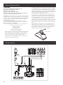
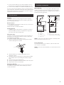
• The grounded 3 prong outlet is to be located inside the
cabinet above the range hood at a minimum distance of
35.8” (91.0 cm) from where the power cord exits the hood.
The grounded 3 prong outlet must be accessible after
installation of the range hood. See illustration:
35.8” (91 cm)
Electrical Requirements
Wiring Diagram

7
GROUNDING INSTRUCTIONS
• This range hood must be grounded. In the event of an electri-
cal short circuit, grounding reduces the risk of electric shock
by providing an escape wire for the electric current.
• This range hood is equipped with a cord having a grounding
wire with a grounding plug. The plug must be plugged into an
outlet that is properly installed and grounded.
WARNING: Improper grounding can result in a risk of electric
shock.
Consult a qualified electrician if the grounding instructions are
not completely understood, or if doubt exists as to whether
the range hood is properly grounded.
Do not use an extension cord. If the power supply cord is too short,
have a qualified electrician install an outlet near the range hood.
SAVE THESE INSTRUCTIONS
Installation Instructions
Prepare location
It is recommended that the vent system be installed before the
range hood is installed.
• Before making cutouts, make sure there is proper clearance
within the ceiling or wall for vent fittings.
• Making the cutout to the bottom of the cabinet may be
easier to do prior to mounting the cabinet to the wall.
1 Disconnect power.
2 Determine which venting method to use: roof, wall, or non
vented.
3 Select a flat surface for assembling the range hood. Place
covering over that surface.
I WARNING
EXCESSIVE WEIGHT HAZARD
USE TWO OR MORE PEOPLE TO MOVE AND INSTALL
RANGE HOOD.
FAILURE TO DO SO CAN RESULT IN BACK OR OTHER INJURY.
4 Using 2 or more people, lift range hood onto covered
surface.
Range hood cabinet cutout
1 Use a saber saw or keyhole saw to cut out the cabinet
bottom inside the cabinet frame.
NOTE: Frameless type cabinets require .7” (1.9 cm) front lip in
the cabinet bottom. A .7” (1.9 cm) thick filler strip (not supplied)
may be required for some types of cabinets. (See Step 3 in
the “Install Range Hood” section).
Cut out dimensions
28.4”
(72.2 cm)
10.9”
(27.8cm)
0.7”
(1.9 cm)
0.5”
(1.27 cm)
Without spacers
(1.27 cm)
0.5”
0.7”
(1.9 cm)
(72.2 cm)
11.9”
(30.3cm)
(1.9 cm)
0.5”
(1.27 cm 0.5”
(1.27 cm)
)
With 1 or 2 spacers
11.4”
(29cm)
1 spacer
2 spacers
0.7”
28.4”
A. Bottom of cabinet cutout
2 Complete cabinet preparation following the instructions
for your type of venting. Determine venting cutout loca-
tions and cut out vent openings in the cabinets, walls and/
or sot.
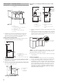
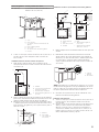
Venting outside through the roof
1 Measure and mark the lines as shown. Use a saber saw or
keyhole saw to cut an opening through the top of the cabinet
and the roof for the vent.
Cutout Chart
Cabinet Height Hole Shape and Size
12” (30.5 cm) A 8.2” wide x 6.2” deep (21 cm x 15.9 cm)
rectangular opening in the cabinet top is
required for damper transition clearance.
A
A
C
D
E
B*
F
G*
A. Cutout
B. 8.2” (21 cm) x 6.2” (15.9 cm)*
C. 7.8” (20 cm) centerline to cabinet front
D. Centerline of the cabinet
E. 4.1” (10.6 cm)
F. 3.2” (8.3 cm) center to cabinet front
G. Ø (4 cm)*

8
Cabinet Height Hole Shape and Size
15” (38.1 cm) A 6.2” (15.9 cm) diameter round opening
is required.
A
A
C
D
B*
E
G*
F
A. Cutout
B. Ø 6.2” (15.9 cm)*
C. 7.7” (19.8 cm) centerline to cabinet front
D. Centerline of the cabinet
E. 4.1” (10.6 cm)
F. 3.2” (8.3 cm) center to cabinet front
G. Ø (4 cm)*
1 Install the 6” (15.2 cm) vent transition to the top of the
range hood liner (if removed for shipping) using two
3.5 x 9.5 mm screws. Assemble the vent duct that you
will use over the 6” (15.2 cm) vent transition.
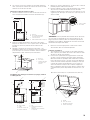
Venting outside through the wall
1 Measure from the bottom of the range hood liner to the
horizontal centerline of the vent opening (A).
A
B
C
DA. Measurement A
B. Horizontal centerline of vent
opening
C. Range hood liner
D. 12” (30.5 cm) min. cabinet height
5 Remove the vent duct from the range hood liner. Transfer
measurement A to the cabinet back wall. Measure from the
underside of the cabinet.
6 Mark the cutout as shown. Use a saber saw or keyhole saw
to cut a round opening through the back of the cabinet and
the exterior wall for the vent.
A
B
C
A. Measurement A
B. Centerline
C. 6.2” (15.9 cm)
round cutout
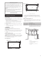
Non-vented (recirculating) installation through the soffit/
cabinet
E
A
B
G
D
F
H
I
A
B
G
F
C
D
E
A. Ceiling
B. Vent cover
C. Sot
D. 6” (15.2 cm) vent
E. Range hood
F. Cabinet
G. Wall
H. 12” (30.5 cm) min. cabinet
height
I. 17” (43.2 cm) min. vent cover
height
1 Measure and mark the centerline of the cabinet to the sot
above.
2 Measure from the bottom of the cabinet to the centerline
of the where the vent will come through the sot. Mark the
location and use a saber saw or keyhole saw to cut a 5.7”
(14.6 cm) hole for the vent cover.
A
B
A. Vent cover
B. Centerline
*NOTE: For 12” (30.5 cm) high cabinets a 5.7” deep x 7.9” wide
(14.6 cm x 20.3 cm) rectangular opening in the cabinet top is
required for damper transition clearance.
3 Consider the cutout chart measures to make the openings
on the cabinet.
Complete preparation
1 If not yet attached, install the 6” (15.2 cm) vent transition
the top of the range hood liner using two 3.5 x 9.5 mm screws.
2 Locate side mounting bracket 1 cm bottom to top side
and against the inside of the front cabinet face. Orient the
bracket depending on the width of your cabinet as depict-
ed in the diagrams below. Drill .1” (3 mm) pilot holes in 6
places, attach a bracket using four 4.5 x 13 mm screws to
each side of the cabinet, and tighten. Additional washers
in hardware package are supplied as spacers for cabinet
walls thinner than .5”(13 mm).

9
Bracket Orientation for 29.4”(74.8 cm) cabinet
Bracket Orientation for 36.7” (93.3cm) cabinet
Move the bracket .3” (1 cm) bot-
tom to top side of the cabinet
3 Install the vent system according to the method needed.
Use caulking to seal the exterior wall or roof opening.
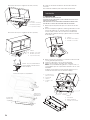
Install range hood
I WARNING
EXCESSIVE WEIGHT HAZARD.
USE TWO OR MORE PEOPLE TO MOVE AND INSTALL
RANGE HOOD.FAILURE TO DO SO CAN RESULT IN BACK OR
OTHER INJURY.
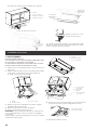
1 Remove the polyurethane piece that comes inside the hood.
2 Center the canopy in the cabinet. Align the bottom of the
canopy with the bottom of the cabinet. Install four 4.2 x 19 mm
screws into the hood canopy assembly and tighten all (8)
mounting screws.
A. Cabinet
B. Hood liner canopy
assembly
C. Screws - 4.2 x 19
mm (8)
A. Cabinet
B. Screws - 4.5 x 13 mm (8)
C. Washers (optional)
D. Mounting bracket (2)
A
B
C
D
A
B
C
D
A. Cabinet
B. Screws - 4.5 x 13 mm (8)
C. Washers (optional)
D. Mounting bracket (2)
Center brackets
into the cabinet
7.7cm
7.6cm
Bracket position without spacers
Bracket position
with 1 spacer
Bracket position
with 2 spacers
6.35cm
Remove the protective from the metal grease filters and
pull them out from the face panel.
4 Pull out the lamps connector cables
5 Attach the face plate to the hood insert. Tighten to secure.
NOTE: If cabinet depth is greater than 12”, it is recommended
that the two .5” metal spacers are installed.
Install to front and rear sides of the face plate with 3.5 x 9.5 mm
screws as shown in drawing.
B
C
C
A
A. Face Panel
B. Front and rear spacer
C. Screws - 3.5 x 9.5 mm (4)
A
BC

10
C
B
A
D
A. Screws - 3.5 x 9.5 mm flat-head (4)
B. Face plate (28.5” x 12”[72.39 cm x 30.5 cm] shown)
C. Cabinet (28.5” x 12” [72.39 cm x 30.5 cm] shown)
D. Screws - 4.2 x 15 mm truss-head (2)
Connect the vent system
Vented Installations
1 Connect the vent system to the range hood vent opening.
Seal the connection with clamps.
Non-Vented (recirculating) Installations
1 Connect the vent system to the range hood vent opening.
Seal the connection with clamps.
2 Install charcoal filters.
See the “Available accesories” section.
Complete installation
1 Replace grease filters. See the “Maintenance” section.
I WARNING
ELECTRICAL SHOCK HAZARD
I WARNING
PLUG INTO A GROUNDED 3 PRONG OUTLET.
DO NOT REMOVE GROUND PRONG.
DO NOT USE AN ADAPTER.
DO NOT USE AN EXTENSION CORD.
FAILURE TO FOLLOW THESE INSTRUCTIONS CAN RESULT
IN DEATH, FIRE, OR ELECTRICAL SHOCK.
2 Plug 3-prong power cord into a grounded 3-prong out-
let located inside the cabinet above the range hood.
3 Check the operation of the range hood fan and light.
See “Description of the hood” section. If range hood does
not operate, check to see whether a circuit breaker has
tripped or a household fuse has blown. Disconnect power
and check wiring connections.
NOTE: To get the most efficient use from your new range
hood, read the “Description of the hood” section.
Description of the hood
The range hood is designed to remove smoke, cooking vapors
and odors from the cooktop area. For best results, start the
hood before cooking and allow it to operate several minutes
after the cooking is complete to clear all smoke and odors
from the kitchen.
The hood controls are located on the center of the front of
the range hood liner.
A
BC
D
A. Blower and light controls
B. Grease filter handle
C. Grease filter
D. LED lamps
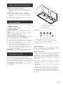
Controls
1. Light On/O button
2. Blower On/O and speed minimum button
3. Blower speed medium button
4. Blower speed maximum button
Operating the light
The Light On/Off button (1) controls both lights. Press once
for On and again for Off.
Operating the blower
The Blower On/Off and speed minimum button (2) turns the
blower On at minimum speed and Off. The Blower Speed
buttons (3 and 4) set the desired speed and control the sound
level for quiet operation. The speed can be changed anytime
during fan operation by pressing the desired blower speed
button.
A. Lamp connector
B. Hood connector
7 Put the filters back in place
6 Connect the lamps connector to the connector present
inside the hood as shown in drawing.
A
B

11
1 To turn the blower On, press the Blower On/O and speed
minimum button (2) and the desired speed button (3 or 4).
2 To turn the blower O, press the Blower On/O button (2).
Any of the 3 blower speed buttons can be in the On position
at the same time. The blower will operate at the highest speed
button that is pushed in. For lower blower speeds, the higher
speed buttons must not be pushed in.
Maintenance
Cleaning
IMPORTANT: Clean the hood and grease filters frequently
according to the following instructions. Replace grease filter
before operating the hood.
Exterior surfaces
To avoid damage to the exterior surface, do not use steel wool
or soap-filled scouring pads.
Always wipe dry to avoid water marks.
Cleaning method:
• Liquid detergent soap and water, or all-purpose cleanser
• Wipe with damp soft cloth or nonabrasive sponge, then
rinse with clean water and wipe dry.
Metal grease filter
The filters should be washed frequently. Place metal filters in
dishwasher or hot detergent solution to clean. Let filter dry
throughly before replacing it.
Turn off fan and lights. Allow lamps to cool.
1 Remove each filter by pulling the spring release handle
and then pulling down the filter.
A
2 Wash metal filters as needed in dishwasher or hot
detergent solution.
3 Reinstall the filter by making sure the spring release handles
are toward the front. Insert metal grease filter into upper
track.
4 Pull the spring release handle down.
5 Push up on metal filter and release handle to latch into place.
6 Repeat steps 1-5 for the other filter.
Replacing a LED lamp
The LED lights are replaceable by a service technician only.
See “Who to contact” section in the warranty for service
contact information.
Available accessories
Carbon filter kit
If it is not possible to vent cooking fumes and vapors to the
outside, the range hood can be used in the non-vented ver-
sion, using a charcoal filter. Kit is available from the dealer or
an authorized parts distributor.
E
A
B
G
D
F
H
I
A
B
G
F
C
D
E
A. Ceiling
B. Vent cover
C. Sot
D. 6” (15.2 cm) vent
E. Range hood
F. Cabinet
G. Wall
H. 12” (30.5 cm) min. cabinet height
I. 17” (43.2 cm) min. vent cover height
NOTE: 12” (30.5 cm) high cabinets without a soffit may allow
the 6” vent and vent cover to be seen.
Cover extension kit
To provide protection for the cabinet, a 30” and a 36” wide
cover extension is available.
NOTE: Kits are purchased separately (see optional accessories
section).

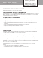
ELICA North America
TWO-YEAR LIMITED WARRANTY
TO OBTAIN SERVICE UNDER WARRANTY
Owner must present proof of original purchase date. Please keep a copy of your dated proof of purchase (sales slip) in
order to obtain service under warranty.
PARTS AND SERVICE WARRANTY
For the period of two (2) years from the date of the original purchase, Elica will provide free of charge, non consumable
parts or components that failed due to manufacturing defects. During these two (2) years limited warranty, Elica will also
provide free of charge, all labor and in-home service to replace any defective parts.
WHAT IS NOT COVERED
• Damage or failure to the product caused by accident or act of God, such as, flood, fire or earthquake.
• Damage or failure caused by modification of the product or use of non-genuine parts.
• Damage or failure to the product caused during delivery, handling or installation.
• Damage or failure to the product caused by operator abuse.
• Damage or failure to the product caused by dwelling fuse replacement or resetting of circuit breakers.
• Damage or failure caused by use of product in a commercial application.
• Service trips to dwelling to provide use or installation guidance.
• Light bulbs, metal or carbon filters and any other consumable part.
• Normal wear of finish.
• Wear to finish due to operator abuse, improper maintenance, use of corrosive or abrasive cleaning products/pads and
oven cleaner products.
WHO IS COVERED
This warranty is extended to the original purchaser for products purchased for ordinary residential use in North America
(Including the United States, Guam, Puerto Rico, US Virgin Islands & Canada).
This warranty is non-transferable and applies only to the original purchaser and does not extend to subsequent owners of
the product. This warranty is made expressly in lieu of all other warranties, expressed or implied, including, but not limited
to any implied warranty of merchantability or fitness for a particular purpose and all other obligations on the part of Elica
North America, provided, however, that if the disclaimer of implied warranties is ineective under applicable law, the dura
-
tion of any implied warranty arising by operation of law shall be limited to two (2) years from the date of original purchase
at retail or such longer period as may be required by applicable law.
This warranty does not cover any special, incidental and/or consequential damages, nor loss of profits, suered by the
original purchaser, its customers and/or the users of the Products.
WHO TO CONTACT
To obtain service under warranty or for any service related question:
• Elica North America Service, call at 1 888 732 8018
• For Eastern Canada, call AGI Services at 1 888 651 2534 Ask for the service department
• elica@servicepower.com
Register your product in
elica.com
and earn a 3rd year of factory
warranty, covering all parts
plus in-home labor.

13
FRANÇAIS
Table des matières
Avis de sécurité important .......................................................................................................................................................................................... 14
Liste des pièces ............................................................................................................................................................................................................... 15
Pièces fournies ........................................................................................................................................................................................................... 15
Pièces non fournies .................................................................................................................................................................................................. 15
Dimensions et dégagement ....................................................................................................................................................................................... 16
Exigences concernant l’évacuation ......................................................................................................................................................................... 16
Exemples et possibilités de positionnement des conduits ............................................................................................................................ 17
Spécifications électriques ........................................................................................................................................................................................... 17
Installation ......................................................................................................................................................................................................................... 20
Achever l’installation ................................................................................................................................................................................................ 21
Description de la hotte ................................................................................................................................................................................................ 21
Commandes ..................................................................................................................................................................................................................... 21
Entretien ............................................................................................................................................................................................................................ 22
Garantie .............................................................................................................................................................................................................................. 23
APPROUVÉ POUR LES APPAREILS DE TYPE RÉSIDENTIEL
POUR UNE UTILISATION RÉSIDENTIELLE SEULEMENT
LISEZ CES INSTRUCTIONS ET CONSERVEZ-LES
VEUILLEZ LIRE CES INSTRUCTIONS AU COMPLET AVANT DE COMMENCER.
L’INSTALLATION DE L’APPAREIL DOIT RESPECTER TOUS LES CODES EN VIGUEUR.
IMPORTANT : Conservez ces instructions afin de pouvoir les remettre à l’inspecteur-électricien de votre région.
INSTALLATEUR : Veuillez laisser ces instructions avec l’appareil pour le propriétaire.
PROPRIÉTAIRE : Veuillez conserver ces instructions pour pouvoir vous y référer plus tard.
Avertissement de sécurité : Coupez l’alimentation du circuit dans le panneau électrique et verrouillez le
panneau avant de raccorder les fils de cet appareil.
Exigence : 120 V c.a., 60 Hz circuit de dérivation de 15 V c.a., 20 Hz, de 15 ou 20 A.
I AVIS DE SÉCURITÉ IMPORTANT
I ATTENTION
UTILISER CET APPAREIL À DES FINS DE VENTILATION
GÉNÉRALE SEULEMENT. NE PAS UTILISER CET APPAREIL
POUR ÉVACUER DES MATÉRIAUX OU DES VAPEURS
DANGEREUX OU EXPLOSIFS.
IAVERTISSEMENT
POUR RÉDUIRE LES RISQUES D’INCENDIE, DE CHOC
ÉLECTRIQUE ET DE BLESSURE, RESPECTER LES DIRECTIVES
SUIVANTES:
A. Utiliser cet appareil uniquement aux fins prévues par le
fabricant. Si vous avez des questions à propos de l’appareil,
communiquez avec le fabricant.
B. Avant de faire l’entretien de l’appareil ou de le nettoyer,
coupez l’alimentation dans le panneau électrique et verrouillez
le panneau en bloquant le dispositif permettant d’empêcher
d’activer l’alimentation accidentellement. S’il n’est pas
possible de verrouiller l’accès au panneau, fixez une étiquette
très voyante au panneau électrique.
C. Une personne qualifiée doit eectuer l’installation et le
câblage des fils électriques en conformité avec tous les
codes et toutes les normes, y compris la cote de résistance
au feu.
D. Il est important de prévoir susamment d’air pour assurer
une bonne combustion de l’équipement de chaue et l’éva-
cuation adéquates des gaz par le conduit de cheminé afin
de prévenir les refoulements d’air. Respectez les directives
et les normes de sécurité des fabricants de l’équipement
de chauage, comme celles publiées par la National Fire
Protection Association (NFPA), la American Society for
Heating, Refrigeration and Air Conditioning Engineers
(ASHRAE) et le code des autorités de votre région.
E. Au moment de couper ou de percer un mur ou un plafond,
assurez-vous de ne pas endommager la filerie électrique
ou tout autre accès à un service publique.
F. Il faut toujours évacuer à l’extérieur les systèmes conduit.
I ATTENTION
Pour réduire les risques d’incendie et évacuer l’air correctement,
assurez-vous que le conduit mène à l’extérieur; il ne faut pas
évacuer l’air dans l’espace entre les murs, dans les plafonds,
dans les greniers, les vides sanitaires ou les garages.
IAVERTISSEMENT
POUR RÉDUIRE DES RISQUES D’INCENDIE, UTILISEZ
UNIQUEMENT DES CONDUITS EN MÉTAL.
Installez cette hotte en respectant toutes les exigences
mentionnées.
IAVERTISSEMENT
Pour réduire les risques d’incendie et de choc électrique,
n’utilisez pas cette hotte avec un contrôleur de vitesse à
semi-conducteurs.

14
LISTE DES PIÈCES
Retirer les pièces de leur emballage.
I ATTENTION
Enlever délicatement le carton, porter des gants pour se protéger des bords coupants.
I AVERTISSEMENT
Enlever le film de protection recouvrant le produit avant de commencer l’opération.
Pièces Fournies Quantité Pièces Fournies Quantité
Assemblage hotte avec souerie
et lampes DEL
1
Changement de capot
1
Brides de montage
2
4,5x13 mm 8Barres d’espacement (pour une
utilisation lorsque la profondeur del
cabinet est supérieure à 12 “)
2
4,2x15 mm 2
3,5x9,5 mm rond vis à tête ronde 6
3,5x9,5 mm vis à tête plate 4
Adaptateur Torx 10 1
4,2x19 mm 8
Rondelles Ø 6,4x18 mm
8
Rondelles Ø 4.2x12 mm
8
I ATTENTION
Dispositif à commande automatique - pour réduire le risque
de Blessure Débrancher de l’alimentation électrique avant la
maintenance.
IAVERTISSEMENT
POUR RÉDUIRE LES RISQUES D’INCENDIE DE GRAISSE SUR
LES CUISINIÈRES.
a) Ne laissez jamais la cuisinière sans surveillance lorsqu’elle
est réglée à une haute température. Les débordements par
bouillonnement causent de la fumée et des débordements
de gras qui peuvent s’enflammer. Faites chauer l’huile
lentement, à une température basse ou moyenne.
b) Faites toujours fonctionner la hotte lorsque vous utilisez
la cuisinière à une haute température ou que vous faites
flamber des aliments (P. ex. : crêpes Suzette, cerises
jubilées, boeuf au poivre flambé).
c) Nettoyez les hélices de ventilation fréquemment. Il ne faut
pas que la graisse s’accumule sur les filres ou les hélices.
d) Utilisez le bon format de casserole. Utilisez toujours un
chaudron de taille approprié à l’élément de la cuisinière.
e) Convient pour utilisation dans la zone de cuisson domestique.
IAVERTISSEMENT
POUR ÉVITER DE BLESSER QUELQU’UN LORS D’UN
INCENDIE DE GRAISSE SUR LA CUISINIÈRE, SUIVRE LES
CONSEILS SUIVANTS:a
a) ÉTOUFFER LES FLAMMES avec un couvercle aux
dimensions de la taque de cuisson, une tôle à biscuit ou
tout autre plateau métallique, puis couper le gaz ou
l’alimentation électrique de la cuisinière. FAIRE
ATTENTION A NE PAS SE BRÛLER. Si les flammes ne
s’éteignent pas immédiatement, QUITTER LA PIÈCE ET
APPELER LES POMPIERS.
b) NE JAMAIS PRENDRE EN MAIN UNE CASSEROLE EN
FEU, vous pourriez vous blesser.
c) NE PAS UTILISER D’EAU, y compris les essuies de vaisselle
ou les serviettes humides – une violente explosion due à la
vapeur formée pourrait survenir.
d) Utiliser un extincteur SEULEMENT si:
1) Vous êtes sûr d’avoir un extincteur de classe ABC que
vous savez utiliser.
2) Le feu est petit et confiné à la zone où il s’est formé.
3) Les pompiers ont été appelés.
4) Vous pouvez lutter contre le feu avec une sortie
derrière vous.
e) Les ventilateurs conduits doivent toujours être évacués
vers l’extérieur.
a Recommandations tirées des conseils de sécurité en cas d’incendie de cuisine
publiés par la NFPA..
MODE OPÉRATOIRE
Toujours laisser les grilles de sécurité et les filtres à leurv
place. Sans la présence de ces derniers, les parties aspirantes
pourraient attirer les cheveux, les doigts ou les vêtements.
Le fabricant décline toute responsabilité si les informations
détaillées dans ce manuel pour l’installation, l’entretien et
l’utilisation adéquate du produit ne sont pas observées. Le
fabriquant décline en outre toute responsabilité pour
d’éventuelles blessures dues à des négligences; en outre, la
garantie de l’appareil sera annulée suite à des conditions
d’entretien inappropriées. Cet appareil est fabriqué pour un
usage interne. Ne pas utiliser cet appareil à l’extérieur.

15
Pièces non Fournies
Outils nécessaires
• Niveau
• Perceuse
• Foret de .1” (3 mm)
• Crayon
• Pince
• Mètre-ruban ou règle
• Pistolet à calfeutrage et composé de calfeutrage résistant
aux intempéries
• Tournevis Phillips
• Tournevis à lame plate
• Scie sauteuse ou scie à guichet
• Brides de conduit
• Cisaille de ferblantier
Pièces nécessaires
• Système de conduit d’évacuation métallique rond de 6”
(15,2 cm)
Accessoires optionnel
KIT # Pièce
28.5” (72.39 cm)
Kit de filtre à charbon KIT0184665
Kit d’extension
Jusqu’à 30”
de large
KIT02773
Jusqu’à 36”
de large
KIT02774
Exigences d’emplacement:
IMPORTANT: Observer les dispositions de tous les codes et
règlements en vigueur.
Confier l’installation de la hotte à un technicien qualifié.
C’est à l’installateur qu’incombe la responsabilité de respecter les
distances de séparation exigées, spécifiées sur la plaque signalétique
de l’appareil.
Installer la hotte de cuisinière à distance de toute zone exposée à
des courants d’air, comme fenêtres, portes et bouches de chauage.
Respecter les dimensions indiquées pour les ouvertures à découper
dans les placards. Ces dimensions tiennent compte des valeurs
minimales des dégagements de séparation.
Avant d’eectuer des découpages, consulter les instructions
d’installation de la table de cuisson/cuisinière. On doit disposer
d’une prise de courant électrique reliée à la terre. Voir la section
“Spécifications électriques”.
La hotte a été configurée à l’usine pour une installation avec e sans
décharge à l’extérieur (recyclage), voir “Installation sans décharge
à l’extérieur (recyclage) à travers le sote/placard”, à la section
“Préparation de l’emplacement”.
Ensemble de filtres à charbon (pièce numéro W10272068) est
disponible chez votre marchand ou chez un distributeur de pièces
autorisé. Assurer l’étanchéité au niveau de chaque ouverture
découpée dans le plafond ou le mur pour l’installation de la hotte
de cuisinière.
Installation dans une résidence mobile
L’installation de cette hotte doit satisfaire aux exigences de la norme
Manufactured Home Construction Safety Standards, Titre 24 CFR,
partie 328 (anciennement Federal Standard for Mobile Home Cons-
truction and Safety, titre 24, HUD, partie 280); lorsque cette norme
n’est pas applicable, l’installation doit satisfaire aux critères de la
plus récente édition de la norme Manufactured Home Installation
1982 (Manufactured Home Sites, Communities and Setups) ANSI
A225.1/NFPA 501A, ou des codes locaux.
†®TORX est une marque déposée de Saturn Fasteners, Inc.
EXIGENCES D’EMPLACEMENT
Dimensions du produit
I* - Barres d’espacement
Pour une utilisation lorsque
la profondeur del cabinet
est supérieure à 12“.
E
A
B
C
F
G
H
D
I*
I*
Modèle
EAS328SS
A28.2” (71.8 cm)
B26” (66 cm)
C1.1” (2.9 cm)
D10.7” (27.3 cm)
E9.5” (24.2 cm)
F0.3” (.95 cm)
G14.5” (37 cm)
H6” (15.2 cm)
I* 0.5” (1.27 cm)
Pour l’installation d’une cuisinière à gaz : Installez cette hotte
de façon à ce que le bord inférieur soit à au moins 30” (76,2
cm) au-dessus de la surface de cuisson.
Pour l’installation d’une cuisinière électrique : installez cette
hotte de façon à ce que le bas soit à au moins 24”(61 cm).

16
E
A
B
C
F
D
A. Hauteur minimale de placard 12”
(30,5 cm)
B. B. Largeur de l’ouverture de
placard 29.4” (74.8) min.
C. C. 24” (61 cm) min. à partir de
la surface de cuisson électrique,
30” (76.2 cm) min. à partir de
la surface de cuisson au gaz;
distance max. suggérée de 36”
(91,4 cm) entre le bas du placard
et la surface de cuisson.
D. Profondeur minimale de
l’armoire de 12” (30,5 cm)
E. Dégagement min. entre le
haut du placard et le plan de
travail de 15” (38,1 cm)
F. Hauteur de placard sur plan-
cher de 36” (91,4 cm)
Remarque : Pour les hottes de 28,5”, il est également possible
d’utiliser une armoire de 93,3 cm (36,7”) de large, en vérifiant
l’orientation des supports lors des étapes suivantes.
Exigences Concernant l’évacuation
• Le circuit d’évacuation doit décharger l’air à l’extérieur,
excepté pour les installations sans décharge à l’extérieur
(recyclage).
• Ne pas terminer le circuit d’évacuation dans un grenier ou
dans un autre espace clos.
• Ne pas utiliser une bouche de décharge murale de 4”
(10,2 cm) normalement utilisée pour un équipement de
buanderie.
• Utiliser un conduit métallique uniquement. Un conduit en
métal rigide est recommandé. Ne pas utiliser de conduit
de plastique ou en aluminium. La longueur du conduit de
décharge et le nombre de coudes doivent être réduits au
minimum pour fournir la meilleure performance.
Pour un fonctionnement ecace et silencieux:
• Ne pas utiliser plus de trois coudes à 90°.
• Veiller à ce qu’il y ait une section droite de conduit d’un
minimum de 24” (61 cm) entre les raccords coudés, si on
doit en utiliser plus d’un.
• Ne pas installer 2 coudes successifs.
• Le circuit d’évacuation doit comporter un clapet anti-r flux.
• Au niveau de chaque jointure du circuit d’évacuation, as-
surer l’étanchéité avec les brides de serrage.
• À l’aide d’un produit de calfeutrage, assurer l’étanchéité
autour de la bouche de décharge à l’extérieur (à travers le
mur ou le toit).
• La taille du conduit doit être uniforme.
Installations dans les régions au climat froid
On doit installer un clapet anti-retour valve supplémentaire
à l’arrière pour minimiser le reflux d’air froid et incorporer un
élément d’isolation thermique pour minimiser la conduction
de chaleur par l’intermédiaire du conduit d’évacuation, de
l’intérieur de la maison à l’extérieur. Le clapet anti-retour valve
doit être placé du côté air froid de la résistance thermique.
Air d’appoint
Les codes du bâtiment locaux peuvent exiger l’emploi
d’un système de renouvellement de l’air/introduction d’air
d’appoint, lors de l’utilisation d’un système d’aspiration de
débit supérieur à une valeur (pieds cubes par minute) spéci-
fiée. Le débit spécifié en pieds cubes par minute varie d’une
juridiction à l’autre.
Consulter un professionnel des installations de chauffage
ventilation/climatisation au sujet des exigences spécifiques
applicables dans la juridiction locale.
Méthodes d’évacuation Recyclage
Cette hotte a été configurée
à l’usine pour la décharge à
travers le toit ou à travers le
mur.
Le système de décharge
requis pour l’installation
n’est pas fourni. Un circuit
d’évacuation avec conduit
circulaire de 6” (15,2 cm) est
recommandé.
A
B
A. Conduit de dia. 6” (15,2 cm)
pour décharge à travers
le placard
B. Grille de recirculation
rond
Décharge à travers le toit Évacuation par le mur
A
B
A. Conduit de dia. 6” (15,2 cm)
pour décharge à travers
le toit
B. Bouche de décharge sur
toit
A
B
A. Conduit de dia. 6” (15,2 cm)
pour décharge à travers
le mur
B. Bouche de décharge
murale

17
Spécications électriques
I AVERTISSEMENT
BRANCHER SUR UNE PRISE À 3 ALVÉOLES RELIÉE À LA TERRE.
NE PAS ENLEVER LA BROCHE DE LIAISON À LA TERRE.
NE PAS UTILISER UN ADAPTATEUR.
NE PAS UTILISER UN CÂBLE DE RALLONGE.
LE NON-RESPECT DE CES INSTRUCTIONS PEUT CAUSER UN
DÉCÈS, UN INCENDIE OU UN CHOC ÉLECTRIQUE.
IMPORTANT: La hotte doit être correctement reliée à la terre
en conformité avec les codes et règlements locaux en vigueur,
ou en l’absence de tels codes, avec le National Electrical Code,
ANSI/ NFPA 70 (dernière édition) ou le Code canadien des
installations électriques, CSA C22.1. No. 0-M91 (dernière édition).
Si les codes le permettent et si on utilise un conducteur dis-
tinct de liaison à la terre, il est recommandé qu’un électricien
qualifié vérifie la qualité de la liaison à la terre. Pour obtenir un
exemplaire des normes des codes ci-dessus, contacter:
National Fire Protection Association
1 Batterymarch Park
Quincy, MA 02169-7471
CSA International
8501 East Pleasant Valley Road
Cleveland, Ohio 44131-5575
• Une alimentation de 120 volts, 60 Hz, CA seulement, de
15 ou 20 ampères, protégée par un fusible est requise. On
recommande également d’utiliser un fusible ou un disjonc-
teur temporisé. Il est recommandé de raccorder la hotte
sur un circuit distinct exclusif à cet appareil.
• Cette hotte est équipée d’un cordon d’alimentation électrique
de liaison à la terre à trois broches.
• Pour minimiser les risques de choc électrique, on doit
brancher le cordon sur une prise de courant de configuration
correspondante, à 3 alvéoles, reliée à la terre et installée
conformément aux codes et règlements locaux. Si une
prise de courant de configuration correspondante n’est
pas disponible, le client a la responsabilité et l’obligation
de faire installer par un électricien qualifié une prise de
courant correctement reliée à la terre.
• La prise à 3 broches reliée à la terre doit se trouver dans
un placard situé au-dessus de la hotte, à une distance mi-
nimale de 35.8” (91 cm) à partir du point duquel le cordon
d’alimentation sort de la hotte. La prise à 3 broches reliée à
la terre doit être accessible une fois la hotte installée. Voir
l’illustration:
•
35.8” (91 cm)
INSTRUCTIONS DE MISE À LA TERRE
• Pour une hotte reliée à la terre et connectée par un cordon:
• Cette hotte doit être reliée à la terre. Au cas où un courtcircuit se
produirait, la liaison à la terre réduit le risque de choc électrique,
en permettant au courant de s’échapper directement vers la terre.
La hotte est équipée d’un cordon comportant un conducteur de
liaison à la terre avec fiche de liaison à la terre. La fiche doit être
branchée dans une prise correctement installée et reliée à la terre.
AVERTISSEMENT: Une mise à la terre incorrecte peut entraîner un
risque de choc électrique.
Consulter un électricien qualifié si les instructions de mise à la terre ne
sont pas complètement comprises, ou si vous avez des doutes quant
à la qualité de la liaison à la terre de la hotte. Ne pas utiliser de câble
de rallonge. Si le cordon d’alimentation électrique est trop court, faire
installer une prise près de la hotte par un électricien qualifié.
CONSERVEZ CES INSTRUCTIONS
Schéma de câblage

18
Instructions d’installation
Préparation de l’emplacement
• BIl est recommandé que l’installation du circuit d’évacuation
soit réalisée avant celle de la hotte.
• Avant de procéder aux découpages, vérifier que les dis-
tances de séparation pour les raccords dans les cavités du
plafond ou du mur sont adéquates.
• Avant de monter le placard au mur, il sera peut-être plus
facile de découper au préalable l’ouverture dans le fond du
placard.
1 Déconnecter la source de courant électrique.
2 Déterminer la méthode d’évacuation à utiliser: décharge à
travers le mur ou le toit, ou recyclage.
3 Choisir une surface plane pour l’assemblage de la hotte.
Placer le matériau de protection sur cette surface.
I AVERTISSEMENT
RISQUE DU POIDS EXCESSIF
UTILISER DEUX OU PLUS DE PERSONNES POUR DÉPLACER
ET INSTALLER LA HOTTE DE LA CUISINIÈRE.
LE NON-RESPECT DE CETTE INSTRUCTION PEUT CAUSER
UNE BLESSURE AU DOS OU D’AUTRE BLESSURE.
4 À l’aide de deux personnes ou plus, soulever la hotte et la
poser sur la surface couverte.
Ouverture découpée du placard pour la hotte
1 Utiliser une scie sauteuse ou scie à guichet pour découper
une ouverture dans le fond du placard, à l’intérieur du
cadre du placard.
REMARQUE: Pour les placards sans cadres, un rebord avant et
arrière de .7” (1,9 cm) est nécessaire pour former un cadre dans
le fond du placard. Une tringle d’appui de .7” (1,9 cm) d’épais-
seur (non fournie) sera peut-être nécessaire pour certains types
de placards).
Ouverture dimensions (sans barres d’espacement)
28.4”
(72.2 cm)
10.9”
(27.8cm)
0.7”
(1.9 cm)
0.5”
(1.27 cm)
Sans barres d’ espacement
(1.27 cm)
0.5”
0.7”
(1.9 cm)
(72.2 cm)
11.9”
(30.3cm)
(1.9 cm)
0.5”
(1.27 cm 0.5”
(1.27 cm)
)
Avec 1 ou 2 barres d’ espacement
11.4”
(29cm)
1 barre
2 barres
0.7”
28.4”
A. Ouverture dans le fond du placard
2 Terminer la préparation du placard conformément aux
instructions correspondant au type d’évacuation du domicile.
Déterminer l’emplacement des ouvertures d’aération et
découper les ouvertures dans les placards, les murs et/ou
les sotes.
Décharge à l’extérieur, à travers le toit
1 Relever les mesures appropriées et tracer les lignes
indiquées sur l’illustration. Utiliser une scie sauteuse ou
une scie à guichet pour découper une ouverture à travers
le sommet du placard et le toit pour l’évacuation.
Mesures appropriées
Hauteur du placard Taille et forme du trou
12” (30,5 cm) Une ouverture rectangulaire de 8.2” de
largeur x 6.2” de profondeur (21 cm x 15,9 cm)
dans le sommet du placard est obligatoire
pour établir le dégagement nécessaire au
clapet anti-reflux.
A
A
C
D
E
B*
F
G*
A. Overture
B. 8.2” (21 cm) x 6.2” (15.9 cm)*
C. 7.8” (20 cm) entre axe et l’avant du placard
D. Axe central
E. 4.1” (10.6 cm)
F. 3.2” (8.3 cm) entre axe et l’avant du placard
G. Ø (4 cm)*
Hauteur du placard Taille et forme du trou
15” (38,1 cm) Une ouverture diamètre rond de 6.2”
(15,9 cm) est obligatoire.
A
A
C
D
B*
E
G*
F
A. Overture
B. Ø 6.2” (15.9 cm)*
C. 7.7” (19.8 cm) entre axe et l’avant du placard
D. Axe central
E. 4.1” (10.6 cm)
F. 3.2” (8.3 cm) entre axe et l’avant du placard
G. Ø (4 cm)*

19
2 S’il n’est pas encore fixé, installer le raccord de transition
de 6” (15,2 cm) au sommet de la caisse de la hotte à l’aide
de deux vis T10 de 3,5 x 9,5 mm.
Décharge à l’extérieur, à travers le mur
1 Mesurer la distance entre le bas de la caisse de la hotte et
l’axe central horizontal de l’ouverture d’évacuation (A).
A
B
C
DA. Mesure A
B. Axe central horizontal de
l’ouverture d’évacuation
C. Caisse de la hotte
D. Hauteur minimum de 12” (30,5 cm)
2 Retirer le conduit d’évacuation de la caisse de la hotte.
Reporter la dimension A sur la paroi arrière du placard.
Prendre les mesures à partir de la face inférieure du
placard.
3 Marquer le périmètre de l’ouverture à découper – voir
l’illustration. Utiliser une scie sauteuse ou une scie à guichet
pour découper une ouverture circulaire à travers l’arrière
du placard et le mur extérieur pour l’évacuation.
A
B
C
A. Mesure A
B. Axe central
C. Ouverture découpée
circulaire de 6.2”
(15,9 cm)
Installation sans décharge à l’extérieur (recyclage) à travers
le sote/placard
E
A
B
G
D
F
H
I
A
B
G
F
C
D
E
A. Plafond
B. Cache-conduit
C. Sote
D. Évent de 6” (15,2 cm)
E. Hotte de cuisinière
F. Placard
G. Mur
H. Hauteur du placard de 12”
(30,5 cm)
I. Hauteur de cache-conduit de
17” (43,2 cm)
1 Relever les mesures appropriées et tracer l’axe central d
placard jusqu’au sote situé au-dessus.
2 Mesurer la distance entre le bas du placard et l’axe central,
au point où le conduit d’évacuation ressort du sote.
Indiquer l’emplacement et utiliser une scie sauteuse ou scie
à guichet pour découper un trou de 5.7” (14,6 cm) pour le
cache-conduit.
A
B
A. Cache- conduit
B. Axe central
*REMARQUE: Pour les placards d’une hauteur de 12” (30,5 cm),
une ouverture rectangulaire de 5.7” de profondeur x 8” de
largeur (14,6 cm x 20,3 cm) dans le sommet du placard est
obligatoire pour établir le dégagement nécessaire au raccord
de transition du clapet anti-reflux.
1 Relever les mesures appropriées et tracer l’axe central
del’ouverture, dans le sommet du placard.
Complete preparation
1 S’il n’est pas encore fixé, installer le raccord de transition
de 6” (15,2 cm) au sommet de la caisse de la hotte à l’aide
de deux vis T10 de 3,5 x 9,5 mm.
2 Positionnez le placard de montage latéral à 1 cm de bas
en haut et contre l’intérieur de la face avant de la bride.
Orienter la bride tel qu’indiqué dans l’illustration suivante.
Percer des avan trous de .1” (3 mm) en 8 points diérents
et fixer une bride à l’aide de quatre vis Phillips n°2 de 4,5
x 13 mm de chaque côté du placard - serrer ensuite. Le
sachet de matériel comporte des rondelles supplémen-
taires en plastique qui peuvent être utilisées comme cales
si l’épaisseur des parois du placard est inférieure à .5” (13
mm).
Orientation de la bride pour un placard de 29.4”(74.8 cm)
A
B
C
D
A. Placard
B. 8 vis - 4,5 x 13 mm
C. Rondelles (facult tives)
D. 2 brides de montage

20
Orientation de la bride pour un placard de 36.7” (93.3cm)
Déplacer le support .3” (1 cm)
du fond côté de l’armoire
3 Installer le circuit d’évacuation selon la méthode requise.
Utiliser un calfeutrant pour assurer l’étanchéité au point de
traversée du mur extérieur ou du toit.
Installation de la hotte
I AVERTISSEMENT
RISQUE DU POIDS EXCESSIF
UTILISER DEUX OU PLUS DE PERSONNES POUR DÉPLACER
ET INSTALLER LA HOTTE DE LA CUISINIÈRE.
LE NON-RESPECT DE CETTE INSTRUCTION PEUT CAUSER
UNE BLESSURE AU DOS OU D’AUTRE BLESSURE.
1 Retirez la pièce en polyuréthane qui se trouve à l’intérieur
de la hotte.
2 Aligner la base de l’auvent avec le bas du placard. Installer
8 vis de 4,2 x 19 mm dans les trous de la plaque de
montage et serrer les vis de montage.
A. Placard
B. Auvent de la hotte
C. 8 vis de 4,2 x 19 mm
3 Retirez le projecteur en plastique et les filtres à graisse
métalliques du panneau avant.
4 Retirez les câbles de connexion des lampes
5 Fixer le panneau à la caisse de la hotte.
REMARQUE: Si la profondeur de l’armoire est supérieur à 12”,
il est recommandé que les deux .5” entretoises métalliques
sont installés.
Installez de faces et arrière del panneau avec vis de 3,5 x 9,5 mm,
comme illustré dans dessin.
6 Branchez le connecteur des lampes au connecteur présent
à l’intérieur du capot comme indiqué dans le dessin.
7 Remettez les filtres en place
A. Placard
B. 8 vis - 4.5 x 13 mm
C. Rondelles (facult tives)
D. 2 brides de montage
A. Panneau
B. Barre de spacement
C. 4 vis - 3,5 x 9,5 mm
Supports de
centrage sur
l’armoire
7.7cm
7.6cm
Position du support sans entretoises
Position du
support avec 1
entretoise
Position du
support avec 2
entretoises
6.35cm
A. 4 vis à tête plate-
3,5 x 9,5 mm
B. Plaque avant
C. Placard
D. 2 vis à tête bombée
- 4,2 x 15 mm
A
B
C
D
A
B
A. Connecteur des lampes
B. Connecteur de la hotte
B
C
C
A
A
BC
C
B
A
D
La page est en cours de chargement...
La page est en cours de chargement...
La page est en cours de chargement...
La page est en cours de chargement...
La page est en cours de chargement...
La page est en cours de chargement...
La page est en cours de chargement...
La page est en cours de chargement...
La page est en cours de chargement...
La page est en cours de chargement...
La page est en cours de chargement...
La page est en cours de chargement...
La page est en cours de chargement...
La page est en cours de chargement...
La page est en cours de chargement...
La page est en cours de chargement...
-
 1
1
-
 2
2
-
 3
3
-
 4
4
-
 5
5
-
 6
6
-
 7
7
-
 8
8
-
 9
9
-
 10
10
-
 11
11
-
 12
12
-
 13
13
-
 14
14
-
 15
15
-
 16
16
-
 17
17
-
 18
18
-
 19
19
-
 20
20
-
 21
21
-
 22
22
-
 23
23
-
 24
24
-
 25
25
-
 26
26
-
 27
27
-
 28
28
-
 29
29
-
 30
30
-
 31
31
-
 32
32
-
 33
33
-
 34
34
-
 35
35
-
 36
36


ELICA EAS328SS Manuel utilisateur
- Catégorie
- Hottes
- Taper
- Manuel utilisateur
dans d''autres langues
- English: ELICA EAS328SS User manual
- español: ELICA EAS328SS Manual de usuario

