La page est en cours de chargement...

Installation
Instructions
Automatic Icemaker
3/4″ Thick Custom Panel Kit
ZIP75WW, ZIP75BB
NOTE: If installing a 3/4″ trimless custom panel, a
1-1/2″ wide filler strip may be required. The filler strip
will act as a spacer between the icemaker case and
the adjacent cabinet, and will prevent interference
with the icemaker door swing when it is installed
between frameless or framed cabinetry. The width of
the cutout opening must include the width of the filler
strip. The product cannot be installed flush to adjacent
24″ deep cabinets with a 3/4″ thick custom panel.
This kit contains a new handle and two side mounting
brackets to support a trimless custom door panel
up to 3/4″ thick. A custom handle may replace the
supplied handle.
IMPORTANT:
• Cut edges of the custom door panel will be seen and
must be finished for best appearance. The back side
of the panel should be finished a minimum of 1/2″
on all sides.
• The custom panel, both raised and flat design,
should be constructed in the same manner as typical
cabinet doors.
• Order the custom panel from the cabinet manufacturer.
Be sure to provide the exact dimensions so that the
panel is constructed accurately.
• BEFORE YOU BEGIN:
Read these instructions completely and carefully.
•
IMPORTANT:
Save these instructions for local inspector’s use.
•
IMPORTANT:
Observe all governing codes and ordinances.
• Note to Installer – Be sure to leave these
instructions with the Consumer.
• Note to Consumer – Keep these instructions with
your Owner’s Manual for future reference.
WARNING:
Disconnect electrical power supply to
icemaker before installing front panel. Do not
operate icemaker while installing panel.
Failure to do so can result in death, fire, or
electrical shock.
AVERTISSEMENT :
Il faut debrancher l’alimentation de la
machine à glaçons avant d’installer le
panneau avant. La machine à glaçons ne
doit pas être en marche pendant l’installation
du panneau avant. Le non-respect de ces
instructions peut causer la mort, un incendie
ou un choc électrique.
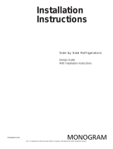
Kit Contents:
• 2 side trim pieces
• 8 side trim screws
• Door handle
Tools and Materials Required:
• 8 flat head wood screws, 1/2″ long
• Drill and 1/8″ bit
• Safety glasses
• Tape
• Custom panel
WARNING
AVERTISSEMENT
14-23/32"
29-1/2"
Left Trim
Right Trim
Handle
Custom
Panel

Pub. No. 49-60043-3
Part No. 197D2521P001
02-06 JR
ZIP75WW–2313617
ZIP75BB–2313618
Printed in the United States
NOTE: While performing installations described in this book,
safety glasses or goggles should be worn.
For Monogram
®
local service in your area, call
1.800.444.1845.
NOTE: Product improvement is a continuing endeavor
at General Electric. Therefore, materials, appearance
and specifications are subject to change without notice.
GE Consumer & Industrial
GE Appliances
General Electric Company
Louisville, KY 40225
ge.com
©2006 GE Company
Installation Instructions
DISCONNECT POWER
TO THE ICE MACHINE
STEP 1
REMOVE HANDLE
AND NAMEPLATE
• Remove the door handle by removing the two top
mounting screws. Set screws aside. Discard handle.
• The Monogram nameplate is held in place with
adhesive. Remove the nameplate.
STEP 2
INSTALL ASSEMBLED PANEL
ONTO THE ICE MACHINE
• Install panel to icemaker with supplied screws,
four on each side.
STEP 6
INSTALL SUPPLIED DOOR
HANDLE (IF USED)
• Install the new supplied handle with original screws.
STEP 7
MARK MOUNTING
SCREW LOCATIONS
• Align and hold the side trim pieces against the
icemaker door and mark screw locations on the sides.
• Drill 1/8″ pilot holes into the door sides of the
icemaker.
STEP 3
SECURE SIDE TRIM PIECES
TO CUSTOM PANEL
• Lay the custom panel appearance-side-down
on a clean surface.
• Align top and bottom side trim to the custom
panel sides.
• Tape the side trim pieces to the back of the
custom panel.
• Place the panel with trim against the door to be sure
that trim and panel fits the door side to side and top
to bottom. Adjust as needed.
• Mark screw locations and remove trim.
Drill pilot holes.
• Install side trim to the back side of the custom
panel with screws (not supplied). Use flat head
wood screws approximately 1/2″ long.
STEP 5
SECURE CUSTOM HANDLE
TO CUSTOM PANEL.
(SKIP THIS STEP IF
YOU ARE USING THE
SUPPLIED HANDLE)
A custom handle can be installed onto the 3/4″ thick
panel, replacing the supplied handle.
• The custom handle can be installed at the top or side
of the panel.
• Drill pilot holes through the front of the custom panel
to match the chosen handle.
• Secure the handle to the panel with flat head wood
screws.
• Replace original handle screws in the top of the door
frame.
STEP 4
/