ELICA ECH623S1 Guide d'installation
- Catégorie
- Hottes
- Taper
- Guide d'installation
Ce manuel convient également à

Use, Care, and Installation Guide
Guide d’utilisation, d’entretien et d’installation
Guía de instalación, uso y mantenimiento
READ AND SAVE THESE INSTRUCTIONS
LISEZ CES INSTRUCTIONS ET CONSERVEZ-LES
LEA Y GUARDE ESTAS INSTRUCCIONES

EN
Contents page 3
FR
Sommaire page 19
ES
Contenido página 35

3
English
Contents
Important safety Notice..............................................................................................................................................4
Electrical & Installation requirements ......................................................................................................................5
Electrical requirements ........................................................................................................................................................................................ 5
Before installing the hood .................................................................................................................................................................................... 5
List of Materials...........................................................................................................................................................6
Parts supplied......................................................................................................................................................................................................6
Parts not supplied................................................................................................................................................................................................6
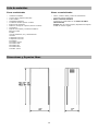
Dimensions and Clearances......................................................................................................................................6
Ducting Options and Examples.................................................................................................................................7
Venting methods.................................................................................................................................................................................................. 7
Preparation .......................................................................................................................................................................................................... 7
Installation...................................................................................................................................................................8
Preparation of the hood for installation:............................................................................................................................................................... 8
Installation - Ducting version................................................................................................................................................................................ 8
Installation - Ductless (Recirculating) version.................................................................................................................................................... 12
Description of the hood & Controls........................................................................................................................16
Controls.............................................................................................................................................................................................................. 16
User Servicing and Maintenance Instructions.......................................................................................................17
Cleaning............................................................................................................................................................................................................. 17
Grease Filter......................................................................................................................................................................................................17
Replacing the light bulb......................................................................................................................................................................................17
Charcoal Filter.................................................................................................................................................................................................... 18
APPROVED FOR RESIDENTIAL APPLIANCES
FOR RESIDENTIAL USE ONLY
READ AND SAVE THESE INSTRUCTIONS
PLEASE READ ENTIRE INSTRUCTIONS BEFORE PROCEEDING.
INSTALLATION MUST COMPLY WITH ALL LOCAL CODES.
IMPORTANT: Save these Instructions for the Local Electrical Inspector’s use.
INSTALLER: Please leave these Instructions with this unit for the owner.
OWNER: Please retain these instructions for future reference.
Safety Warning: Turn off power circuit at service panel and lock out panel, before wiring this appliance.
Requirement: 120 V AC, 60 Hz. 15 or 20 A Branch Circuit

4
READ AND SAVE THESE INSTRUCTIONS
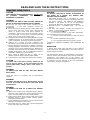
Important safety Notice
CAUTION
FOR GENERAL VENTILATING USE ONLY. DO NOT USE
TO EXHAUST HAZARDOUS OR EXPLOSIVE
MATERIALS OR VAPOURS.
WARNING
TO REDUCE THE RISK OF FIRE, ELECTRIC SHOCK, OR
INJURY TO PERSONS, OBSERVE THE FOLLOWING:
A. Use this unit only in the manner intended by the
manufacturer. If you have questions, contact the
manufacturer.
B. Before servicing or cleaning the unit, switch power off at
service panel and lock service panel disconnecting
means to prevent power from being switched on
accidentally. When the service disconnecting means
cannot be locked, securely fasten a prominent warning
device, such as a tag, to the service panel.
C. Installation Work and Electrical Wiring Must Be Done By
Qualified Person(s) In Accordance With All Applicable
Codes & Standards, Including Fire-rated Construction.
D. Sufficient air is needed for proper combustion and
exhausting of gases through the flue (Chimney) of fuel
burning equipment to prevent back- drafting. Follow the
heating equipment manufacturers guideline and safety
standards such as those published by the National Fire
Protection Association (NFPA), the American Society for
Heating, Refrigeration and Air Conditioning Engineers
(ASHRAE), and the local code authorities.
E. When cutting or drilling into wall or ceiling, do not
damage electrical wiring and other hidden utilities.
F. Ducted systems must always be vented to the outdoors.
CAUTION
To reduce risk of fire and to properly exhaust air, be
sure to duct air outside - do not vent exhaust air into
spaces within walls, ceilings, attics, crawl spaces, or
garages.
WARNING
TO REDUCE THE RISK OF FIRE, USE ONLY METAL
DUCT WORK.
Install this hood in accordance with all requirements
specified.
WARNING
To Reduce The Risk Of Fire Or Electric Shock, Do Not
Use This Hood With Any External Solid State Speed
Control Device.
WARNING
TO REDUCE THE RISK OF A RANGE TOP GREASE
FIRE.
a) Never leave surface units unattended at high settings.
Boilovers cause smoking and greasy spillovers that may
ignite. Heat oils slowly on low or medium settings.
b) Always turn hood ON when cooking at high heat or when
flambeing food (I.e. Crepes Suzette, Cherries Jubilee,
Peppercorn Beef Flambe’).
c) Clean ventilating fans frequently. Grease should not be
allowed to accumulate on fan or filter.
d) Use proper pan size. Always use cookware appropriate
for the size of the surface element.
WARNING
TO REDUCE THE RISK OF INJURY TO PERSONS, IN
THE EVENT OF A RANGE TOP GREASE FIRE,
OBSERVE THE FOLLOWING
a
:
a) SMOTHER FLAMES with a close-fitting lid, cookie
sheet, or other metal tray, then turn off the gas burner or
the electric element. BE CAREFUL TO PREVENT
BURNS. If the flames do not go out immediately,
EVACUATE AND CALL THE FIRE DEPARTMENT.
b) NEVER PICK UP A FLAMING PAN - you may be
burned.
c) DO NOT USE WATER, including wet dishcloths or
towels - a violent steam explosion will result.
d) Use an extinguisher ONLY if:
1) You know you have a class ABC extinguisher,
and you already know how to operate it.
2) The fire is small and contained in the area where
it started.
3) The fire department is being called.
4) You can fight the fire with your back to an exit.
a
Based on "Kitchen Firesafety Tips" published by
NFPA.
OPERATION
a. Always leave safety grills and filters in place. Without
these components, operating blowers could catch onto hair,
fingers and loose clothing.
The manufacturer declines all responsibility in the event of
failure to observe the instructions given here for installation,
maintenance and suitable use of the product. The
manufacturer further declines all responsibility for injury due
to negligence and the warranty of the unit automatically
expires due to improper maintenance.

5
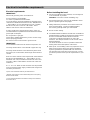
Electrical & Installation requirements
Electrical requirements
IMPORTANT
Observe all governing codes and ordinances.
It is the customer’s responsibility:
To contact a qualified electrical installer.
To assure that the electrical installation is adequate and in
conformance with National Electrical Code, ANSI/NFPA 70
— latest edition*, or CSA Standards C22.1-94, Canadian
Electrical Code, Part 1 and C22.2 No.0-M91 - latest
edition** and all local codes and ordinances.
If codes permit and a separate ground wire is used, it is
recommended that a qualified electrician determine that the
ground path is adequate.
Do not ground to a gas pipe.
Check with a qualified electrician if you are not sure range
hood is properly grounded.
Do not have a fuse in the neutral or ground circuit.
IMPORTANT
Save Installation Instructions for electrical inspector’s use.
The range hood must be connected with copper wire only.
The range hood should be connected directly to the fused
disconnect (Or circuit breaker) box through metal electrical
conduit.
Wire sizes must conform to the requirements of the National
Electrical Code ANSI/NFPA 70 — latest edition*, or CSA
Standards C22.1-94, Canadian Electrical Code Part 1 and
C22.2 No. 0-M91 - latest edition** and all local codes and
ordinances.
A U.L.- or C.S.A.-listed conduit connector must be provided
at each end of the power supply conduit (at the range hood
and at the junction box).
Copies of the standards listed may be obtained from:
* National Fire Protection Association Batterymarch Park Quincy,
Massachusetts 02269
** CSA International 8501 East Pleasant Valley Road Cleveland,
Ohio 44131-5575
Before installing the hood
1. For the most efficient air flow exhaust, use a straight run
or as few elbows as possible.
CAUTION: Vent unit to outside of building, only.
2. At least two people are necessary for installation. Wear
gloves to protect against sharp edges.
3. Fittings material is provided to secure the hood to most
types of walls/ceilings, consult a Qualified Installer,
check if they perfectly fit with your cabinet/wall.
4. Do not use flex ducting.
5. COLD WEATHER installations should have an additional
backdraft damper installed to minimize backward cold air
flow and a nonmetallic thermal break to minimize
conduction of outside temperatures as part of the
ductwork. The damper should be on the cold air side of
the thermal break.
The break should be as close as possible to where the
ducting enters the heated portion of the house.
6. Make up air: Local building codes may require the use of
Make-Up Air Systems when using Ducted Ventilation
Systems greater than specified CFM of air movement.
The specified CFM varies from locale to locale. Consult
your HVAC professional for specific requirements in your
area.

6
List of Materials
Parts supplied
• Blower unit housing
• Hood canopy
• Stainless steel mesh filter
• Halogen light bulb x 2
• Upper and lower Duct covers x 4
• Chimney structure
• Deflector, 3 pieces to assemble, (ductless version)
• 4 Casings
• Hardware Packet:
Control shaft
Template
Use, Care and Installation Guide
Warranty
Torx adapter T10 x 1
Torx adapter T20 x 1
6 washers
3,5x9,5 screws x 14
5x45 screws x 10
4x8 screws x 16
M4x7 screws x 10
4,2x15 screws x 4
Parts not supplied
• Duct, conduit and all tools required for installation.
• Ductless Recirculating Kit
To be used only in the Ductless (Recirculating)
version
includes: charcoal filter, charcoal filter fixing devices.
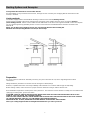
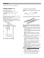
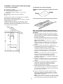
Dimensions and Clearances

7
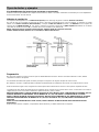
Ducting Options and Examples
Closely follow the instructions set out in this manual.
All responsibility, for any eventual inconveniences, damages or fires caused by not complying with the instructions in this
manual, is declined.
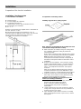
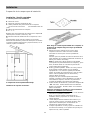
Venting methods
The hood is equipped with a transition B for discharge of fumes to the outside (Ducting version).
Should it not be possible to discharge cooking fumes and vapour to the outside, the hood can be used in the Ductless
(Recirculating) version. Attach a charcoal filter and the deflector F on the duct cover support bracket G. Fumes and vapours
are recycled through the top grille H by means of a duct connected to the transition B and the transition mounted on the
deflector F.
NOTE: For ductless (Recirculating) version only: purchase the Ductless Recirculating Kit.
Minimum Duct Size (Ducting/Ductless version): 8" Round Pipe.
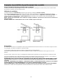
Preparation
Do not cut a joist or stud unless absolutely necessary. If a joist or stud must be cut, then a supporting frame must be
constructed.
Fittings material is provided to secure the hood to most types of walls/ceilings.
However, a qualified technician must verify suitability of the materials in accordance with the type of wall/ceiling.
Before making cutouts, make sure there is proper clearance within the ceiling or wall for exhaust vent.
Hood installation height above cooktop is the users preference. The lower the hood is above the cooktop, the more efficient the
capturing of cooking odors, grease and smoke.
CAUTION: FOR GAS RANGES INSTALLATION: MOUNT THIS HOOD SO THAT THE BOTTOM EDGE IS NOT LESS
THAN 30" (76,2 CM) ABOVE THE COOKING SURFACE.
FOR ELECTRIC RANGES INSTALLATION: MOUNT THIS HOOD SO THAT THE BOTTOM EDGE IS NOT LESS THAN 24"
(61 CM) AND NO MORE THAN 30" (76,2 CM) ABOVE THE COOKING SURFACE.
HOUSEHOLD USE. PLEASE, READ INSTALLATION MANUAL FOR SPECIFIC APPLICATION.
Check your ceiling height and the hood height maximum before you select your hood.

8
Installation
Preparation of the hood for installation:
Installation - Ducting version
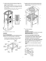
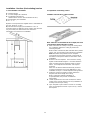
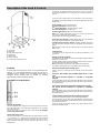
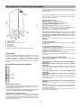
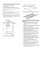
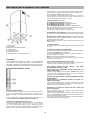
1. Pre-installation calculations
K
= Kitchen Height
C = Counter Height (36" standard)
P = Prefered Height of Hood
Bottom above counter (Recommended 24”-30”)
H = Hood height your installation
H = K – C – P
a) Select a hood preference height P that is comfortable for
the user. (from 24” to 30“).
b) Calculate Hood height your installation H = K-C-P.
c) Confirm that H is within the range of min to max H found
for your model (See “Dimensions and clearances”
paragraph). If not adjust your installation.
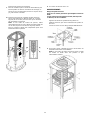
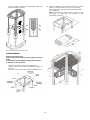
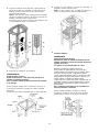
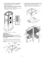
2. Preparation of mounting surface
Installing supports above ceiling drywall.
Note: Take into consideration the hood depth; the hood
could be much deeper than the cooktop.
a. Mark center lines of cooktop or range on ceiling above.
Use centerlines marked on ceiling to position the
mounting template.
Note location of hood front (that indicated with a printed
arrow), side, and mounting holes indicated on template.
Note: Remember that printed arrow on template
corresponds to front of the hood and consequently to
side where control panels will be located at the end of
installation)
b. Remove and save template. Cut and remove ceiling
drywall. Install suitable length 2" x 4" lumber between
joists to provide chimney mounting points as shown
above. Use template for dimensions and required
clearance.
Make sure to affix the added lumber firmly and level.
Consult a professional if you have difficulties or your
installation is unique. Consult template and Figs.above.
c. Install a 8” exhaust duct and extend length = H - 28“
from ceiling. Duct shall be securely fastened to joists.
Do not use duct smaller than specified.
Attention: Duct installation is not required for non-
vented (recirculating) installations
d. Install 1/2" electrical conduit in location marked on
template and extend length from ceiling.
Note: If a Remote ventilator installation is
required/needed, then provide an additional
hole/conduit.
e. Install drywall around duct and conduit; then refinish
ceiling, leave enough clearance for easy installation of
chimney structure up to ceiling.
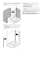
f. Tape Template in place and fit 4 screws on mounting
holes, do not tighten but leave a space of 1/2“, remove
the template.

9
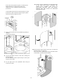
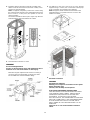
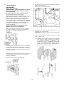
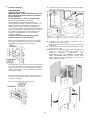
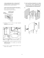
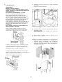
3. Regulate chimney structure and fix all assembly parts
with 4 screws to each bracket (16 screws in total), check
structure is well assembled.
Note: If supplied, temporarily remove the screws fixing
the reinforcement bracket to the perforated frame (keep
these screws in a safe place) and position it over the
motor assembly.
The bracket should be fixed in place again only after the
perforated frame has been fitted to the ceiling.
4. Hook the frame onto the 4 screws.
WARNING
Excessive Weight Hazard
Use two or more people to move and install range hood.
Failure to do so can result in back or other injury.
Make final angular adjustment to structure at ceiling if
necessary then securely tighten 4 ceiling lag screws.
Fit six additional screws for definitive fixing.
5. Connect the other end of the exhaust pipe to the flue.
Note: If supplied, fix the reinforcement bracket to the
perforated frame in a position which is as near to the
middle as possible.
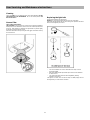
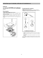
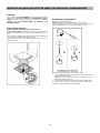
6.
Electrical connection
WARNING
Electrical Shock Hazard
Warning: Turn off power circuit at the service panel
before wiring this unit.
120 VAC, 15 or 20 Amp circuit required.
ELECTRICAL GROUNDING INSTRUCTIONS
THIS APPLIANCE IS FITTED WITH AN ELECTRICAL
JUNCTION BOX WITH 3 WIRES, ONE OF WHICH
(GREEN/YELLOW) SERVES TO GROUND THE
APPLIANCE. TO PROTECT YOU AGAINST
ELECTRIC SHOCK, THE GREEN AND YELLOW WIRE
MUST BE CONNECTED TO THE GROUNDING WIRE
IN YOUR HOME ELECTRICAL SYSTEM, AND IT
MUST UNDER NO CIRCUMSTANCES BE CUT OR
REMOVED.
Failure to do so can result in death or electrical
shock.
Remove the knockout and the Junction box cover and
install the conduit connector (cULus listed) in junction
box.

10
Run 3 wires; black, white and green ,according to the
National Electrical Code and local codes and
ordinances, in 1/2" conduit from service panel to
junction box.
Connect black wire from service panel to black or red in
junction box, white to white and green to green-yellow.
Close and secure junction box cover.
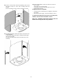
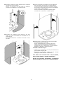
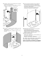
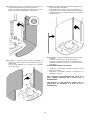
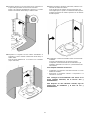
7. Fit the control shaft in the correct position by pushing it
upwards.
Connect the electricity.
8. Join the two upper sections of the duct covering the
perforated frame.
Fix each individual section in place using 2 screws (1 per
side) near the ceiling.
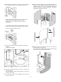
9. Fix the upper duct to the perforated frame using 10
screws (5 per side).
10. Apply 2 casings (supplied) to cover the fixing points
on the upper duct sections (CAUTION: THE
UPPER DUCT CASINGS ARE EASY TO
RECOGNISE BECAUSE THEY ARE WIDER,
DEEPER AND ARE FITTED BY PRESSING
THEM INTO PLACE).
11. First insert the lower section of the duct, on which the
threaded inserts can be found.
Fix it to the frame, tightening the first and fourth screws
on both sides (counting from the bottom).

11
12. Join the second lower section by tightening the second
and third screws on each side (counting from the
bottom).
Fix the 2 sections in place using 4 screws (2 per side).
11. Assemble the lower (narrow) trim strips to the lower vent
cover assembly.
Cut the upper (wide) trim strips to length to fit the upper
duct cover assembly.
Assemble the upper trim strips to the upper duct cover
assembly.
14. Check all light bulbs to make sure they are secure in
their sockets.
Turn power on in service panel.
Check lights and blower operation per Care & Use
section of this manual.
If range hood does not operate:
• Check that the circuit breaker is not tripped or the house
fuse blown.
• Disconnect power supply. Check that wiring is correct.
To get the most efficient use from your new range hood,
read the “Use and Care Information” section.
Keep your Installation Instructions and Use and Care
Guide close to range hood for easy reference.

12
Installation - Ductless (Recirculating) version
1. Pre-installation calculations
K
= Kitchen Height
C = Counter Height (36" standard)
P = Prefered Height of Hood
Bottom above counter (Recommended 24”-30”)
H = Hood height your installation
H = K – C – P
a) Select a hood preference height P that is comfortable for
the user. (from 24” to 30“).
b) Calculate Hood height your installation H = K-C-P.
c) Confirm that H is within the range of min to max H found
for your model (See “Dimensions and clearances”
paragraph). If not adjust your installation.
2. Preparation of mounting surface
Installing supports above ceiling drywall.
Note: Take into consideration the hood depth; the hood
could be much deeper than the cooktop.
a. Mark center lines of cooktop or range on ceiling above.
Use centerlines marked on ceiling to position the
mounting template.
Note location of hood front (that indicated with a printed
arrow), side, and mounting holes indicated on template.
Note: Remember that printed arrow on template
corresponds to front of the hood and consequently to
side where control panels will be located at the end of
installation)
b. Remove and save template. Cut and remove ceiling
drywall. Install suitable length 2" x 4" lumber between
joists to provide chimney mounting points as shown
above. Use template for dimensions and required
clearance.
Make sure to affix the added lumber firmly and level.
Consult a professional if you have difficulties or your
installation is unique. Consult template and Figs.above.
c. Install 1/2" electrical conduit in location marked on
template and extend length from ceiling.
Note: If a Remote ventilator installation is
required/needed, then provide an additional
hole/conduit.
d. Install drywall around duct and conduit; then refinish
ceiling, leave enough clearance for easy installation of
chimney structure up to ceiling.
e. Tape Template in place and fit 4 screws on mounting
holes, do not tighten but leave a space of 1/2“, remove
the template.

13
3. Regulate chimney structure and fix all assembly parts
with 4 screws to each bracket (16 screws in total), check
structure is well assembled.
Note: If supplied, temporarily remove the screws fixing
the reinforcement bracket to the perforated frame (keep
these screws in a safe place) and position it over the
motor assembly.
The bracket should be fixed in place again only after the
perforated frame has been fitted to the ceiling.
4. Hook the frame onto the 4 screws.
WARNING
Excessive Weight Hazard
Use two or more people to move and install range hood.
Failure to do so can result in back or other injury.
Make final angular adjustment to structure at ceiling if
necessary then securely tighten 4 ceiling lag screws.
Fit six additional screws for definitive fixing.
5. Fit deflector to the truss and secure it to the bracket
supplied using 4 screws, then connect the exhaust pipe
to the connection ring located on the deflector.
Note: If supplied, fix the reinforcement bracket to the
perforated frame in a position which is as near to the
middle as possible.
6.
Electrical connection
WARNING
Electrical Shock Hazard
Warning: Turn off power circuit at the service panel
before wiring this unit.
120 VAC, 15 or 20 Amp circuit required.
ELECTRICAL GROUNDING INSTRUCTIONS
THIS APPLIANCE IS FITTED WITH AN ELECTRICAL
JUNCTION BOX WITH 3 WIRES, ONE OF WHICH
(GREEN/YELLOW) SERVES TO GROUND THE
APPLIANCE. TO PROTECT YOU AGAINST
ELECTRIC SHOCK, THE GREEN AND YELLOW WIRE
MUST BE CONNECTED TO THE GROUNDING WIRE
IN YOUR HOME ELECTRICAL SYSTEM, AND IT
MUST UNDER NO CIRCUMSTANCES BE CUT OR
REMOVED.
Failure to do so can result in death or electrical
shock.

14
Remove the knockout and the Junction box cover and install
the conduit connector (cULus listed) in junction box.
Run 3 wires; black, white and green ,according to the
National Electrical Code and local codes and
ordinances, in 1/2" conduit from service panel to
junction box.
Connect black wire from service panel to black or red in
junction box, white to white and green to green-yellow.
Close and secure junction box cover.
7. Fit the control shaft in the correct position by pushing it
upwards.
Connect the electricity.
8. Join the two upper sections of the duct covering the
perforated frame.
Fix each individual section in place using 2 screws (1 per
side) near the ceiling.
9. Fix the upper duct to the perforated frame using 10
screws (5 per side).
10. Apply 2 casings (supplied) to cover the fixing points on
the upper duct sections (CAUTION: THE UPPER DUCT
CASINGS ARE EASY TO RECOGNISE BECAUSE
THEY ARE WIDER, DEEPER AND ARE FITTED BY
PRESSING THEM INTO PLACE).
11. First insert the lower section of the duct, on which the
threaded inserts can be found.
Fix it to the frame, tightening the first and fourth screws
on both sides (counting from the bottom).

15
12. Join the second lower section by tightening the second
and third screws on each side (counting from the
bottom).
Fix the 2 sections in place using 4 screws (2 per side).
11. Assemble the lower (narrow) trim strips to the lower vent
cover assembly.
Cut the upper (wide) trim strips to length to fit the upper
duct cover assembly.
Assemble the upper trim strips to the upper duct cover
assembly.
14. Check all light bulbs to make sure they are secure in
their sockets.
Turn power on in service panel.
Check lights and blower operation per Care & Use
section of this manual.
If range hood does not operate:
• Check that the circuit breaker is not tripped or the house
fuse blown.
• Disconnect power supply. Check that wiring is correct.
To get the most efficient use from your new range hood,
read the “Use and Care Information” section.
Keep your Installation Instructions and Use and Care
Guide close to range hood for easy reference.

16
Description of the hood & Controls
1. Control panel
2. Grease filter
3. Grease filter release handle
4. Halogen lamp
5. Vapour catcher
6. Telescopic chimney
7. Air outlet (used for filter version only)
Controls
Use the high suction speed in cases of concentrated kitchen
vapours. It is recommended that the cooker hood suction is
switched on for 5 minutes prior to cooking and to leave in
operation during cooking and for another 15 minutes
approximately after terminating cooking.
Description of control panel
Automatic start-up function
The hood is equipped with a temperature sensor which activates the motor to the
first suction speed (power) in the event that the temperature in the surrounding
area is higher than 70°C.
The user may switch off or modify the suction speed (power) (see paragraph
“suction speed (power) control”).
Suction speed (power) control
The suction speed (power) is cyclical depending on the speed sequence “stand-by
– 1-2-3-4- Stand by -1-2-...” therefore every time the T1 button is pressed on the
control panel, the suction speed (power) is increased by one level, in order to
switch off (stand-by) if the button is pressed again when the hood is in suction
speed (power) 4.
The hood may be switched off (stand-by) while the hood is set on any speed by
holding down the T1 button on the control panel for a bit longer (more than 3
seconds).
The hood's suction speed (power) may be determined as the control panel is
equipped with a LED light that changes colors as follows, depending on the suction
speed (power):
Hood in stand-by: LED LIGHT SWITCHED OFF
1
st
suction speed (power) -GREEN LED LIGHT
2
nd
suction speed (power) – ORANGE LED LIGHT (amber)
3
rd
suction speed (power) - RED LED LIGHT
4
th
suction speed (power) - RED LED LIGHT (FLASHING)
Note: The 4
th
suction speed (power) stays on for 5 minutes, after which the
suction motor will position itself on the 2
nd
speed.
If pressed again, the suction motor will switch off (stand-by).
Grease filters need cleaning: FLASHING GREEN LED light (read instructions
found under “Reset and configuration for filter saturation signal”)
Coal filters must be cleaned or replaced: FLASHING ORANGE (amber) LED
light (read instructions found under “Reset and configuration for filter saturation
signal”)
Note: The reset procedure may be activated by both the control panel and the
remote control.
Center light check
The center light may be switched on and off by pressing the T2 button on the
control panel.
Side light check (when scheduled)
The side lights may be switched on and off by pressing AND HOLDING DOWN the
T2 button on the control panel.
HOLDING DOWN the button, besides permitting to switch the hood on and off, it
also regulates the light intensity given from the lights.
Note: The switching on and off functions (and regulating function) alternate.
The regulation of the light intensity is not available for hoods with neon lights.
Reset and configuration for filter saturation signal
Switch on hood to any speed (see above paragraph “Suction speed (power)
selection”)
Reset grease filter saturation signal (FLASHING GREEN LIGHT on control
panel)
First proceed with filter maintenance as described in corresponding
paragraph.
Press and hold down (for more than 3 seconds) the T1 button on the control panel,
the LED light will stop flashing indicating that the signal reset has been carried out,
the hood will switch off.
Reset coal filter saturation signal (FLASHING ORANGE (amber) LED light)
First proceed with filter maintenance as described in corresponding
paragraph.
Press and hold down (for more than 3 seconds) the T1 button on the control panel,
the LED light will stop flashing indicating that the signal reset has been carried out,
the hood will switch off.
Coal filter saturation signal disactivaction (for particular applications)
Switch off hood (see above paragraph “suction speed (power) selection”).
Press and hold down (for more than 5 seconds) the T1 button on the control panel,
the LED light will start flashing GREEN indicating that the coal filter saturation
signal has been disactivated.
In order to reactivate the coal filter saturation signal, repeat operation, the LED
light will flash ORANGE (amber)

17
User Servicing and Maintenance Instructions
Cleaning
Clean using ONLY the cloth dampened with neutral liquid detergent. DO NOT
CLEAN WITH TOOLS OR INSTRUMENTS. Do not use abrasive products. DO
NOT USE ALCOHOL!
Grease Filter
Traps cooking grease particles.
The grease filter must be cleaned once a month using non aggressive detergents,
either by hand or in the dishwasher, which must be set to a low temperature and a
short cycle. When washed in a dishwasher, the grease filter may discolor slightly,
but this does not affect its filtering capacity.
Remove the filter holder frame by turning the knobs (g) 90° that affix the chimney
to the cooker hood.
Replacing the light bulb
Disconnect the appliance from the electricity.
Warning! Prior to touching the light bulbs ensure they are cooled down.
Replace the old light bulb with the one of the same type as specified in the feature
label or near the light lamp on the hood.
• Use a small screwdriver as a lever on the borders of the lamp in order to
remove the lightbulb.
• Slide out the lightbulb to be replaced and replace with a new 12V 20W MAX
30° Ø35 12V GU4.
• Carry out the replacement and mount the new lightbulb by following
instructions in the reverse.
If the lights do not work, make sure that the lamps are fitted properly into their
housings before you call for technical assistance.

18
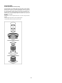
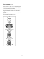
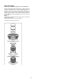
Charcoal Filter
It absorbs unpleasant odors caused by cooking.
The charcoal filter can be washed once every two months (or when the filter
saturation indication system – if envisaged on the model in possession – indicates
this necessity) using hot water and a suitable detergent, or in a dishwasher at
65°C (if the dishwasher is used, select the full cycle function and leave dishes out).
Eliminate excess water without damaging the filter, then put it in the oven for 10
minutes at 100° C to dry completely. Replace the mattress every 3 years and
when the cloth is damaged.
Assembly
Place the mat around the grease filter and fix it in place using the devices
provided.
Position the upper cap and fix it in place using the fixing pin.
To disassemble, perform the steps in the reverse order.

19
French
Sommaire
Avis de sécurité important.......................................................................................................................................20
Exigences électriques et exigences d’installation................................................................................................21
Exigences électriques........................................................................................................................................................................................ 21
Avant d’installer la hotte..................................................................................................................................................................................... 21
Liste des pièces........................................................................................................................................................22
Pièces fournies ..................................................................................................................................................................................................22
Pièces non fournies ...........................................................................................................................................................................................22
Dimensions et Dégagement.....................................................................................................................................22
Exemples et possibilités de positionnement des conduits .................................................................................23
Méthodes de ventilation..................................................................................................................................................................................... 23
Préparation ........................................................................................................................................................................................................ 23
Installation.................................................................................................................................................................24
Préparation de la hotte pour l'installation:..........................................................................................................................................................24
Installation - Version à conduit........................................................................................................................................................................... 24
Installation - Version sans conduit (Recyclage)................................................................................................................................................. 28
Description de la hotte et des commandes ...........................................................................................................32
Commandes....................................................................................................................................................................................................... 32
Instructions pour l’entretien, utilisateur et la maintenance .................................................................................33
Nettoyage........................................................................................................................................................................................................... 33
Filtre à graisse ...................................................................................................................................................................................................33
Remplacement des ampoules ........................................................................................................................................................................... 33
Filtres à charbon................................................................................................................................................................................................34
APPROUVÉ POUR LES APPAREILS DE TYPE RÉSIDENTIEL
POUR UNE UTILISATION RÉSIDENTIELLE SEULEMENT
LISEZ CES INSTRUCTIONS ET CONSERVEZ-LES
VEUILLEZ LIRE CES INSTRUCTIONS AU COMPLET AVANT DE COMMENCER.
L’INSTALLATION DE L’APPAREIL DOIT RESPECTER TOUS LES CODES EN VIGUEUR.
IMPORTANT : Conservez ces instructions afin de pouvoir les remettre à l’inspecteur-électricien de votre
région.
INSTALLATEUR : Veuillez laisser ces instructions avec l’appareil pour le propriétaire.
PROPRIÉTAIRE : Veuillez conserver ces instructions pour pouvoir vous y référer plus tard.
Avertissement de sécurité : Coupez l’alimentation du circuit dans le panneau électrique et verrouillez le
panneau avant de raccorder les fils de cet appareil.
Exigence : 120 V c.a., 60 Hz circuit de dérivation de 15 V c.a., 20 Hz, de 15 ou 20 A.

20
LISEZ CES INSTRUCTIONS ET CONSERVEZ-LES
Avis de sécurité important
ATTENTION
UTILISER CET APPAREIL À DES FINS DE VENTILATION
GÉNÉRALE SEULEMENT. NE PAS
UTILISER CET
APPAREIL POUR ÉVACUER DES MATÉRIAUX OU DES
VAPEURS DANGEREUX OU EXPLOSIFS.
AVERTISSEMENT
POUR RÉDUIRE LES RISQUES D’INCENDIE, DE CHOC
ÉLECTRIQUE ET DE BLESSURE, RESPECTER LES
DIRECTIVES SUIVANTES :
A. Utiliser cet appareil uniquement aux fins prévues par le
fabricant. Si vous avez des questions à propos de
l’appareil, communiquez avec le fabricant.
B. Avant de faire l’entretien de l’appareil ou de le nettoyer,
coupez l’alimentation dans le panneau électrique et
verrouillez le panneau en bloquant le dispositif
permettant d’empêcher d’activer l’alimentation
accidentellement. S’il n’est pas possible de verrouiller
l’accès au panneau, fixez une étiquette très voyante au
panneau électrique.
C. Une personne qualifiée doit effectuer l’installation et le
câblage des fils électriques en conformité avec tous les
codes et toutes les normes, y compris la cote de
résistance au feu.
D. Il est important de prévoir suffisamment d’air pour
assurer une bonne combustion de l’équipement de
chauffe et l’évacuation adéquates des gaz par le conduit
de cheminé afin de prévenir les refoulements d’air.
Respectez les directives et les normes de sécurité des
fabricants de l’équipement de chauffage, comme celles
publiées par la National Fire Protection Association
(NFPA), la American Society for Heating, Refrigeration
and Air Conditioning Engineers (ASHRAE) et le code
des autorités de votre région.
E. Au moment de couper ou de percer un mur ou un
plafond, assurez-vous de ne pas endommager la filerie
électrique ou tout autre accès à un service publique.
F. Il faut toujours évacuer à l’extérieur les systèmes à
conduit.
ATTENTION
Pour réduire les risques d’incendie et évacuer l’air
correctement, assurez-vous que le conduit mène à
l’extérieur; il ne faut pas évacuer l’air dans l’espace
entre les murs, dans les plafonds, dans les greniers, les
vides sanitaires ou les garages.
AVERTISSEMENT
POUR RÉDUIRE DES RISQUES D’INCENDIE, UTILISEZ
UNIQUEMENT DES CONDUITS EN MÉTAL.
Installez cette hotte en respectant toutes les exigences
mentionnées.
AVERTISSEMENT
Pour réduire les risques d’incendie et de choc
électrique, n’utilisez pas cette hotte avec un contrôleur
de vitesse à semi-conducteurs.
AVERTISSEMENT
POUR RÉDUIRE LES RISQUES D’INCENDIE DE
GRAISSE SUR LES CUISINIÈRES.
a) Ne laissez jamais la cuisinière sans surveillance
lorsqu’elle est réglée à une haute température. Les
débordements par bouillonnement causent de la fumée
et des débordements de gras qui peuvent s’enflammer.
Faites chauffer l’huile lentement, à une température
basse ou moyenne.
b) Faites toujours fonctionner la hotte lorsque vous utilisez
la cuisinière à une haute température ou que vous faites
flamber des aliments (P. ex. : crêpes Suzette, cerises
jubilées, bœuf au poivre flambé).
c) Nettoyez les hélices de ventilation fréquemment. Il ne
faut pas que la graisse s’accumule sur les filres ou les
hélices.
d) Utilisez le bon format de casserole. Utilisez toujours un
chaudron de taille approprié à l’élément de la cuisinière.
AVERTISSEMENT
POUR ÉVITER DE BLESSER QUELQU’UN LORS D’UN
INCENDIE DE GRAISSE SUR LA CUISINIÈRE, SUIVRE
LES CONSEILS SUIVANTS
a
:
a) ÉTOUFFER LES FLAMMES avec un couvercle aux
dimensions de la taque de cuisson, une tôle à biscuit ou
tout autre plateau métallique, puis couper le gaz ou
l’alimentation électrique de la cuisinière. FAIRE
ATTENTION A NE PAS SE BRÛLER. Si les flammes ne
s’éteignent pas immédiatement, QUITTER LA PIÈCE ET
APPELER LES POMPIERS.
b) NE JAMAIS PRENDRE EN MAIN UNE CASSEROLE
EN FEU, vous pourriez vous blesser.
c) NE PAS UTILISER D’EAU, y compris les essuies de
vaisselle ou les serviettes humides – une violente
explosion due à la vapeur formée pourrait survenir.
d) Utiliser un extincteur SEULEMENT si:
1) Vous êtes sûr d’avoir un extincteur de classe ABC que
vous savez utiliser.
2) Le feu est petit et confiné à la zone où il s’est formé.
3) Les pompiers ont été appelés.
4) Vous pouvez lutter contre le feu avec une sortie
derrière vous.
a
Recommandations tirées des conseils de sécurité en cas
d'incendie de cuisine publiés par la NFPA.
MODE OPéRATOIRE
a. Toujours laisser les grilles de sécurité et les filtres à leur
place. Sans la présence de ces derniers, les parties
aspirantes pourraient attirer les cheveux, les doigts ou
les vêtements.
Le fabricant décline toute responsabilité si les informations
détaillées dans ce manuel pour l’installation, l’entretien et
l’utilisation adéquate du produit ne sont pas observées. Le
fabriquant décline en outre toute responsabilité pour
d’éventuelles blessures dues à des négligences; en outre, la
garantie de l’appareil sera annulée suite à des conditions
d’entretien inappropriées. Cet appareil est fabriqué pour un
usage interne. Ne pas utiliser cet appareil à l’extérieur.
La page est en cours de chargement...
La page est en cours de chargement...
La page est en cours de chargement...
La page est en cours de chargement...
La page est en cours de chargement...
La page est en cours de chargement...
La page est en cours de chargement...
La page est en cours de chargement...
La page est en cours de chargement...
La page est en cours de chargement...
La page est en cours de chargement...
La page est en cours de chargement...
La page est en cours de chargement...
La page est en cours de chargement...
La page est en cours de chargement...
La page est en cours de chargement...
La page est en cours de chargement...
La page est en cours de chargement...
La page est en cours de chargement...
La page est en cours de chargement...
La page est en cours de chargement...
La page est en cours de chargement...
La page est en cours de chargement...
La page est en cours de chargement...
La page est en cours de chargement...
La page est en cours de chargement...
La page est en cours de chargement...
La page est en cours de chargement...
La page est en cours de chargement...
La page est en cours de chargement...
La page est en cours de chargement...
La page est en cours de chargement...
-
 1
1
-
 2
2
-
 3
3
-
 4
4
-
 5
5
-
 6
6
-
 7
7
-
 8
8
-
 9
9
-
 10
10
-
 11
11
-
 12
12
-
 13
13
-
 14
14
-
 15
15
-
 16
16
-
 17
17
-
 18
18
-
 19
19
-
 20
20
-
 21
21
-
 22
22
-
 23
23
-
 24
24
-
 25
25
-
 26
26
-
 27
27
-
 28
28
-
 29
29
-
 30
30
-
 31
31
-
 32
32
-
 33
33
-
 34
34
-
 35
35
-
 36
36
-
 37
37
-
 38
38
-
 39
39
-
 40
40
-
 41
41
-
 42
42
-
 43
43
-
 44
44
-
 45
45
-
 46
46
-
 47
47
-
 48
48
-
 49
49
-
 50
50
-
 51
51
-
 52
52


ELICA ECH623S1 Guide d'installation
- Catégorie
- Hottes
- Taper
- Guide d'installation
- Ce manuel convient également à
dans d''autres langues
- English: ELICA ECH623S1 Installation guide
- español: ELICA ECH623S1 Guía de instalación