Simplicity 071035-00 Manuel utilisateur
- Catégorie
- Groupes électrogènes
- Taper
- Manuel utilisateur

Installation &
Operator’s Manual
Questions?
Help is just a moment away!
Call: Helpline
(800) 743-4115 M-F 8-5 CT
BRIGGSandSTRATTON.COM
Model 071013 Revision 01
201925GS Rev. A (04/23/2007)

Briggs & Stratton Power Products Group, LLC
900 North Parkway
Jefferson, WI 53549
Copyright © 2007 Briggs & Stratton Power Products Group, LLC.
All rights reserved. No part of this material may be reproduced or
transmitted in any form by any means without the express written
permission of Briggs & Stratton Power Products Group, LLC.
Thank you for your purchase of this Briggs & Stratton Power Products Power Management System. This product is intended
for use with Briggs & Stratton Home Standby Generator sets ONLY. This is an optional home standby system which provides
an alternate source of electric power and to serve loads such as a gas furnace, refrigeration and communication systems that,
when stopped during any power outage, could cause discomfort, or the like. This product DOES NOT qualify for emergency
standby as defined by NFPA 70 (NEC).
This manual contains safety information to make you aware of the hazards and risks associated with power management
systems and how to avoid them. Briggs & Stratton has made every effort to provide for a safe, streamlined and cost-effective
installation. Each installation is unique, it is impossible to know of and advise of all conceivable procedures and methods by
which installation might be achieved. We do not know all possible hazards and/or the results of each method or procedure.
Save these instructions for future reference.
This power management system requires installation before use. Refer to the Installation section of this manual for
instructions on installation procedures. Only licensed electrical contractors should install power management systems.
Installations must strictly comply with all applicable federal, state and local codes, standards and regulations.
Where to Find Us
You never have to look far to find Briggs & Stratton support and service for your power management system. Consult your
Yellow Pages. There are over 30,000 Briggs & Stratton authorized service dealers worldwide who provide quality service. You
can also contact Briggs & Stratton Customer Service by phone at (800) 743-4115, or on the Internet at
BRIGGSandSTRATTON.COM.
Power Management System
Model Number
Revision
Serial Number
Date Purchased

1
FrançaisEspañol
Table Of Contents
Important Safety Instructions . . . . . . . . . . . . . . . . . . . . . . . . . . . . . . . . . 2
Owner Orientation . . . . . . . . . . . . . . . . . . . . . . . . . . . . . . . . . . . . . . . . . . . . 3
Installer Responsibilities . . . . . . . . . . . . . . . . . . . . . . . . . . . . . . . . . . . . . . . 3
Equipment Description. . . . . . . . . . . . . . . . . . . . . . . . . . . . . . . . . . . . . . . . . 3
Installation . . . . . . . . . . . . . . . . . . . . . . . . . . . . . . . . . . . . . . . . . . . . . 4
Unpacking . . . . . . . . . . . . . . . . . . . . . . . . . . . . . . . . . . . . . . . . . . . . . . . . . . 4
Mounting Guidelines . . . . . . . . . . . . . . . . . . . . . . . . . . . . . . . . . . . . . . . . . . 4
Power Wiring Interconnections . . . . . . . . . . . . . . . . . . . . . . . . . . . . . . . . . . 5
System Setup. . . . . . . . . . . . . . . . . . . . . . . . . . . . . . . . . . . . . . . . . . . . . . . . 6
Testing the Power Management System . . . . . . . . . . . . . . . . . . . . . . . . . . . 7
Controls . . . . . . . . . . . . . . . . . . . . . . . . . . . . . . . . . . . . . . . . . . . . . . . 7
Operation . . . . . . . . . . . . . . . . . . . . . . . . . . . . . . . . . . . . . . . . . . . . . . 7
Wiring Decal . . . . . . . . . . . . . . . . . . . . . . . . . . . . . . . . . . . . . . . . . . . . . . . . 8
Electrical Load Worksheet . . . . . . . . . . . . . . . . . . . . . . . . . . . . . . . . . . . . . . 9
Maintenance . . . . . . . . . . . . . . . . . . . . . . . . . . . . . . . . . . . . . . . . . . . 10
Specifications. . . . . . . . . . . . . . . . . . . . . . . . . . . . . . . . . . . . . . . . . . . . . . . 10
Troubleshooting . . . . . . . . . . . . . . . . . . . . . . . . . . . . . . . . . . . . . . . . . 11
Illustrated Parts List. . . . . . . . . . . . . . . . . . . . . . . . . . . . . . . . . . . . . . . . . . 12
Warranty . . . . . . . . . . . . . . . . . . . . . . . . . . . . . . . . . . . . . . . . . . . . . . 13

2 BRIGGSandSTRATTON.COM
Important Safety Instructions
This is the safety alert symbol. It is used to alert
you to potential personal injury hazards. Obey all
safety messages that follow this symbol to avoid
possible injury or death.
The safety alert symbol ( ) is used with a signal word
(DANGER, CAUTION, WARNING), a pictorial and/or a safety
message to alert you to hazards. DANGER indicates a hazard
which, if not avoided, will result in death or serious injury.
WARNING indicates a hazard which, if not avoided, could
result in death or serious injury. CAUTION indicates a hazard
which, if not avoided, might result in minor or moderate
injury. NOTICE indicates a situation that could result in
equipment damage. Follow safety messages to avoid or
reduce the risk of injury or death.
The manufacturer cannot possibly anticipate every possible
circumstance that might involve a hazard. The warnings in
this manual, and the tags and decals affixed to the unit are,
therefore, not all-inclusive. If you use a procedure, work
method or operating technique that the manufacturer does
not specifically recommend, you must satisfy yourself that it
is safe for you and others. You must also make sure that the
procedure, work method or operating technique that you
choose does not render the power management system
unsafe.
Save These Instructions
• Use power management system only for intended uses.
• If you have questions about intended use, ask dealer or contact
Briggs and Stratton Power Products.
• Do not expose power management system to excessive
moisture, dust, dirt, or corrosive vapors.
• Remain alert at all times while working on this equipment. Never
work on the equipment when you are physically or mentally
fatigued.
• If connected devices overheat, turn them off and turn off their
circuit breaker/fuse.
NOTICE
Improper treatment of power management system can
damage it and shorten its life.
• Do not touch bare wires.
• Do not use power management system with worn, frayed, bare
or otherwise damaged wiring.
• Do not handle electrical cords while standing in water, while
barefoot, or while hands or feet are wet.
• If you must work around a unit while it is operating, stand on an
insulated dry surface to reduce shock hazard.
• Do not allow unqualified persons or children to operate or
service power management system.
• In case of an accident caused by electrical shock, immediately
shut down all sources of electrical power and contact local
authorities. Avoid direct contact with the victim.
WARNING
Failure to properly ground power management
system can result in electrocution.
• Despite the safe design of the power management system,
operating this equipment imprudently, neglecting its
maintenance or being careless can cause possible injury or
death.
WARNING
Power management system contains high voltage
that can cause personal injury or death.
• Failure to follow above warning could cause personal injury,
damage and/or malfunction of equipment.
WARNING
Low voltage wire cannot be installed in same
conduit as power voltage wiring.
WARNING
Only qualified electricians should attempt installation of
this system, which must strictly comply with applicable
codes, standards and regulations.

3
Introduction
Your Briggs & Stratton Power Management System is
supplied with this combined “Installation and Operator’s
Manual”. This is an important document and should be
retained by the owner after the installation has been
completed.
Every effort has been expended to make sure that the
information in this manual is both accurate and current.
However, the manufacturer reserves the right to change, alter
or otherwise improve the system at any time without prior
notice.
For the Home Owner
To help you make informed choices and communicate
effectively with your installation contractor(s),
Read and understand the Owner Orientation Section
of this manual before contracting or starting your
power management system installation.
To arrange for proper installation, contact the store at which
you purchased your power management system, your dealer,
or your utility power provider.
The power management system warranty is VOID
unless the system is installed by a
licensed electrical professional.
Owner Orientation
The illustrations provided are for typical circumstances and
are meant to familiarize you with the installation options
available with your power management system.
Local codes, appearance, and distances are the factors that
must be considered when negotiating with an installation
professional. As the distance from the existing electrical
service increases, compensation in wiring materials must be
allowed for. This is necessary to comply with local codes and
overcome electrical voltage drops.
The factors mentioned above will have a direct effect on
the overall price of your power management system
installation.
NOTE: Your installer must check local codes AND obtain
permits before installing the system.
• Read and follow the instructions given in this manual.
• Follow a regular schedule in caring for and using your
power management system, as specified in this
manual.
Installer Responsibilities
• Read and observe the safety rules.
• Read and follow the instructions given in this manual.
• Check federal, state and local codes.
• Consult with owner to determine loads to be controlled
and their priorities.
NOTE: A worksheet for determining which loads are to be
transferred and their priorities is provided on page 9.
• The installer may need to provide appropriate rated
contactors based on loads to be controlled.
Equipment Description
The power management system is designed to control
six priority loads and up to two air conditioner loads that are
being supplied by power from the home standby system.
This power management system goes into a STANDBY mode
and does not control any loads when utility power is present.
The power management system consists of a relay board
with 6 relays to control loads rated up to 120 VAC, 20 Amps,
1 hp, and a control module that has 2 relays for central air
conditioner loads. The circuit boards are housed in a NEMA
3R enclosure that is suitable for both indoor and outdoor
installations.
Two (2) current transformers monitor generator current at
the transfer switch to ensure that the loading of the
generator does not exceed 85 percent. Should load exceed
85 percent, the power management system will shed loads
to keep the generator from overloading. The power
management system will add load back once sufficient
current is available.
The control module has a green LED for each relay to
indicate when the relays are supplying power to the loads
when on generator power. There is also a status LED that
flashes when the power management system is functioning
properly.

Installation
Unpacking
Delivery Inspection
After removing the carton, carefully inspect the power
management system components for any damage that may
have occurred during shipment.
IMPORTANT: If loss or damage is noted at time of delivery,
have the person(s) making delivery note all damage on the
freight bill and affix his signature under the consignor's
memo of loss or damage. If loss or damage is noted after
delivery, contact the carrier for claim procedures. Missing or
damaged parts are not warranted.
Shipment Contents
• Power Management System
• Installation and Operator’s Manual
• Wire Connectors (4)
• 1/4” Double Male, Single Female Lugs (2)
Mounting Guidelines
The power management system is enclosed in a NEMA
Type 3R enclosure suitable for indoor/outdoor use.
Guidelines for mounting the power management system
include:
• Install power management system on a firm, sturdy
supporting structure.
• The power management system must be installed with
minimum NEMA 3R hardware for conduit connections.
• Level and plumb the enclosure. This can be done by
placing washers between the power management
system enclosure and the mounting surface.
• Never install the power management system where any
corrosive substance might drip onto the enclosure.
• Protect the power management system at all times
against excessive moisture, dust, dirt, lint, construction
grit and corrosive vapors.
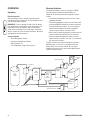
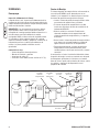
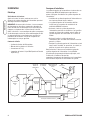
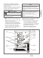
A typical installation of the power management system is
depicted below. It is best if it is mounted near the main
breaker panel, either inside or outside. Discuss layout
suggestions/changes with the owner before beginning the
system installation process.
4 BRIGGSandSTRATTON.COM
Main
Breaker
Panel
Transfer
Switch
Hot
Water
Heater
Air
Conditioner
Service Disconnect
Generator
Watt -
Hourmeter
Branch Circuits
Disconnect Switch
Power
Manage-
ment
System
Contactor

5
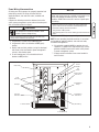
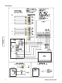
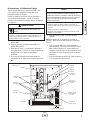
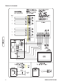
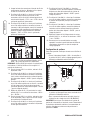
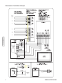
Power Wiring Interconnections
All wiring must be the proper size, properly supported and
protected by conduit. All wiring should be done per
applicable federal, state and local codes, standards and
regulations.
Complete the following connections between the transfer
switch, power management system and main breaker panel.
Also see the Wiring Decal on page 8.
1. Set generator’s system switch to OFF position.
2. Set generator’s main circuit breaker to OFF (open)
position.
3. Identify loads and their priorities (using list developed
with owner) to be transferred to power management
system in main breaker panel.
4. In main breaker panel, turn selected load circuit
breakers to OFF position.
5. Connect “GND” lug to an approved ground.
NOTE: Assure grounding electrode conductor is connected
and bonded per applicable federal, state and local codes,
standards and regulations.
6. Using installer supplied 300VAC or greater wire and
supplied 1/4” double male, single female lugs, connect
generator 240VAC from transfer switch to relay board
in power management system.
7. Unplug current transformers from control module in
transfer switch.
Ground Lug
To Transfer Switch
Air Conditioner
Relays
Load
Connection
Control
Module
Test
Button
Generator
Connection
Air Conditioner
Connections
Relay Board
To Air Conditioners
Transfer Switch
Connections
Green LED’s
Wireways
• Failure to follow above warning could cause personal injury,
damage and/or malfunction of equipment.
WARNING
Low voltage wire cannot be installed in same
conduit as power voltage wiring.
• Remove all power prior to installing this power management
system. Failure to do so could cause internal damage to the
board when making electrical connections.
• Turn generator to OFF position.
• Turn off utility power to the home standby generator and transfer
switch.
NOTICE
Improper installation can cause damage to the circuit
boards and shorten their life. Installing circuit boards in live
circuits will damage the board and is not a warranty
condition. ALWAYS disconnect ALL sources of power prior
to servicing.

8. Cut two pin connector ends off of current transformer
leads and discard. Strip wires and place in supplied
wire connectors.
9. Using installer supplied 300VAC or greater wire, run
wires from wire connectors to control module terminal
block labeled “CT1A” through “CT2B” in power
management system.
10. Using installer supplied 300VAC or greater wire,
connect C (Common) and NO (Normally Open)
terminals on terminal strip J9 of control module in
transfer switch to control module terminal block labeled
“TXSF” and “TXFG” in power management system.
11. Wire the air conditioner thermostat control wiring to the
control module labeled “AC1A-AC2B” in power
management system.
NOTE: AC1A and AC1B is for the priority 1 air conditioner.
AC2A and AC2B is for the priority 2 air conditioner.
12. For 120VAC selected loads, remove wire from selected
load circuit breaker.
13. Using installer supplied 300VAC or greater wire,
connect selected load circuit breaker to terminal block
at power management system labeled “CB/B1” for
priority 1 load.
14. Using installer supplied 300VAC or greater wire and a
wire nut, connect the selected load wire to terminal
block in power management system labeled “RLY/B1”
for priority 1 load.
15. Repeat steps 12 through 14 for all other 120VAC
priorities using terminals “CB/C1” through “RLY/D2”.
16. For 240VAC selected loads, remove both wires from
selected load circuit breaker and place in load side of
installer supplied contactor.
17. Using installer supplied 300VAC or greater wire,
connect circuit breaker to line side of contactor.
18. Using installer supplied 300VAC or greater wire,
connect one pole of the circuit breaker to terminal block
in power management system labeled “CB/B1” for a
priority 1 load.
19. Using installer supplied 300VAC or greater wire,
connect Neutral in main breaker panel to contactor coil.
20. Using installer supplied 300VAC or greater wire,
connect contactor coil to terminal block in power
management system labeled “RLY/B1” for a priority 1
load.
21. Repeat steps 16 through 20 for all other 240VAC
priorities using terminals “CB/C1” through “RLY/D2”.
22. Tighten all wire connections/fasteners to proper torque.
See inside power management system enclosure for
proper torque values.
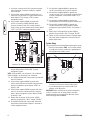
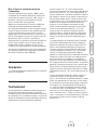
System Setup
You must perform the following before operating the system:
• Place the switch labeled “SW2” on the control module
in the NG or LP position, whichever is appropriate for
the installed home standby system.
• Place the switch labeled “SW3” on the control module
to match the rating of the home standby system.
• In main breaker panel, turn selected load circuit
breakers to the ON position.
IMPORTANT: After installation of the power management
system is complete, turn on utility power to the home
standby generator and transfer switch. Wait one minute
before turning generator to AUTO.
6 BRIGGSandSTRATTON.COM
SW3
SW2
Location of J9 Terminal Strip in Transfer Switch

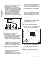
Testing the Power Management System
With the generator in “AUTO“ position, turn the service
disconnect feeding the transfer switch contactor to the “Off”
position. The generator will start and the transfer switch will
transfer to generator power.
Press the test button on the control module of the power
management system. As the button is pressed, a relay will
energize. Each time the button is pressed, the previous relay
that was energized, will de-energize and the next relay will
energize.
Press the test button once and relay B2 will energize. Press
the test button again and B2 will de-energize and relay C1 will
energize. This will proceed until all relays have been tested or
if the test button has not been pressed for a period of 30
seconds, the test sequence will halt and the system will go
back to automatic control.
To go back to utility power, turn the service disconnect
feeding the transfer switch contactor to the “On” position.
Controls
There are no operator controls in this Power Management
System.
Operation
When the home standby system is providing power to the
transfer switch, the power management system is constantly
monitoring generator power to control loads. The power
management system monitors both incoming generator lines
and keeps the home standby system loaded to a maximum
of 85-86 percent of rated load. When the current
transformers on any line start to see current reach 85-86
percent of rated load, the power management system will
start shedding loads based on the lowest priority and work
its way to the highest priority. When current has dropped
below 85-86 percent of rated load, the power management
system will start to add loads based on the highest priority
first, followed by the second highest until the generator
reaches 85-86 percent load or all priorities are back on line.
The power management system will operate this way until
the transfer switch transfers back to utility position.
The power management system waits 5 seconds between
adding or shedding each load to permit the system to
stabilize. When a relay is opened, the relay will stay opened
for a minimum of 5 minutes or until the load can be added
without putting the generator over 85-86 percent of rated
load. If a large load demand is seen, the power management
system will shed all loads in less than 1.5 seconds to
prevent the generator from overloading. Once the demand
has stabilized, the power management system will start with
the highest priority, wait 5 seconds and then add the next
priority. The unit will continue to do this until all loads are
added or 85-86 percent of rated load is reached.
When the generator is powering loads, the A/C relays are
open. When one or both of the relays sense 24VAC from the
thermostat(s), the controller will shed loads B1-D2, and then
will allow only one A/C relay to close. A1 has priority over
A2. A2 can close when the signal for A1 has expired. When
the A/C’s are being called to run, all loads are to be shed
before the A/C unit can be added. Should A/C 1 call while
A/C 2 is running, A/C 2 shall open, all relays would open and
then A/C 1 can close. When the A/C relays open, they are to
be locked out for a minimum of 5 minutes or until they
receive a call to start the A/C.
7

8 BRIGGSandSTRATTON.COM
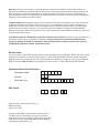
Wiring Decal

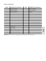
9
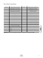
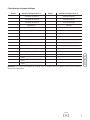
Priority 120VAC Electrical Appliances Priority 240VAC Electrical Appliances
Window Air Conditioner 1 Central Air Conditioner 1
Window Air Conditioner 2 Central Air Conditioner 2
Window Air Conditioner 3 Range/Stove
Refrigerator 1 Dryer
Refrigerator 2 Well Pump
Freezer 1 Hot Tub
Freezer 2 Pool Heater
Microwave Water Heater
Bathroom Other:________________________
Auxiliary Heater Other:________________________
Home Theater System Other:________________________
Garage Heater
Sink Water Heater
Sewage Lift Pump
Other:________________________
Other:________________________
Other:________________________
IMPORTANT: DO NOT connect furnace, sewage pump and sump pump to power management system.
Electrical Load Worksheet

10 BRIGGSandSTRATTON.COM
Maintenance
The power management system is designed to be
maintenance free under normal usage. However, inspection
and maintenance checks should be made on a regular basis.
Maintenance will consist mainly of keeping the power
management system clean.
Visual inspections should be done at least once a month.
Access to power management system must not be
obstructed. Keep 3 feet (92 cm) clearance around power
management system. Check for an accumulation of dirt,
moisture and/or corrosion on and around the enclosure,
loose parts/hardware, cracks and/or discoloration to
insulation, and damaged or discolored components.
Exercise the power management system at least once every
three months as described in the previous section Testing
the Power Management System unless a power outage
occurs and Home Generator System has gone through
automatic sequence. Allow generator to run for at least
30 minutes.
Contact a licensed electrical professional to inspect and clean
the inside of your power management system at least once a
year.
When Calling the Factory
Before contacting Briggs & Stratton regarding service or
repair of this power management system, obtain the Model
Number and Serial Number from the unit data decal located
on or inside the enclosure.
To contact Briggs & Stratton call (800) 743-4115, between
8:00 AM and 5:00 PM CT.
Specifications
Rated AC Voltage . . . . . . . . . . . . . . . . . . . . . . .125/250 Volts
Frequency . . . . . . . . . . . . . . . . . . . . . . . . . . . . . . . .50/60 Hz
Relay Contacts
Rating . . . . . . . . . .125 VAC, 20A, 1 HP, 768 VA Pilot Duty
Dimensions . . . . . .Approximately 16” H X 12” W X 6” Deep
Weight . . . . . . . . . . . . . . . . . . . . . . . . . . . . . . . . . . . .34 lbs.

11
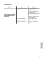
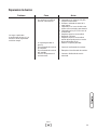
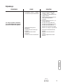
Troubleshooting
Problem Cause Correction
Supervised loads (air conditioner, etc.)
are not operating when generator is
supplying power
1. AC1A-AC2B contacts not operating
correctly.
2. Too much load on generator.
3. Current transformer not connected.
4. Broken current transformer.
5. Status LED stays lit constantly.
1A. Check AC1A-AC2B contacts for
proper operation.
B. Check control wiring to external
load.
C. Check harness between boards is
properly connected.
D. Check that there is 24 VAC to one of
the terminals.
E. Be sure 5 minute lock out has
elapsed.
F. Be sure air conditioner start time
delay has elapsed.
2. Decrease load to generator.
3. Connect current transformer.
4. Replace current transformer.
5. Contact an authorized service
center.

12 BRIGGSandSTRATTON.COM
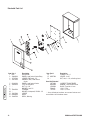
Illustrated Parts List
Item Part # Description
1 NSP ENCLOSURE
2 196616GS BOARD, Load Control Center Relay
3 197979GS SPACER, PCB Board, 1/2"
4 198112GS HARNESS, Wire, Load Control
Center
5 201924GS BOARD, Load Control Center
6 198431GS CLIP, Latching Wire
7 * NUT, 1/4 - 20
8 * WASHER, Lock 1/4
9 186345GS TERMINAL
10 * WASHER, Shakeproof, Ext M6 - 1/4
11 192150GS SPACER
12 202426GS DECAL
13 198655GS DECAL, Warning
Item Part # Description
14 * PPHMS, 8-32 x 1
15 200574GS SPACER, 4 x 25
16 * NUT, Hex, 8 - 32, w/Locking Insert
Items Not Illustrated
195728GS CURRENT TRANSFORMER
201925GS MANUAL, Load Control Center
197956GS BLOCK, Terminal w/ Levrs
74094GS LUG, 1/4 Tab
77211GS LUG, 1/4, 18-22
* - Items without part numbers are common fasteners and
are available at local hardware stores.

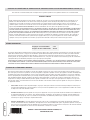
Warranty
13
BRIGGS & STRATTON POWER PRODUCTS GROUP, LLC TRANSFER SWITCH OWNER WARRANTY POLICY
LIMITED WARRANTY
Briggs & Stratton Power Products Group, LLC will repair or replace, free of charge, any part(s) of the equipment that is defective in material or
workmanship or both. Transportation charges on product submitted for repair or replacement under this warranty must be borne by purchaser. This
warranty is effective for the time periods and subject to the conditions stated below. For warranty service, find the nearest Authorized Service Dealer in
our dealer locator map at BRIGGSandSTRATTON.COM.
THERE IS NO OTHER EXPRESS WARRANTY. IMPLIED WARRANTIES, INCLUDING THOSE OF MERCHANTABILITY AND FITNESS FOR A PARTICULAR
PURPOSE, ARE LIMITED TO ONE YEAR FROM PURCHASE, OR TO THE EXTENT PERMITTED BY LAW. ANY AND ALL IMPLIED WARRANTIES ARE
EXCLUDED. LIABILITY FOR INCIDENTAL OR CONSEQUENTIAL DAMAGES ARE EXCLUDED TO THE EXTENT EXCLUSION IS PERMITTED BY LAW. Some
states or countries do not allow limitations on how long an implied warranty lasts, and some states or countries do not allow the exclusion or limitation
of incidental or consequential damages, so the above limitation and exclusion may not apply to you. This warranty gives you specific legal rights and
you may also have other rights which vary from state to state or country to country.
3 years
None
Consumer Use
Commercial Use
The warranty period begins on the date of purchase by the first retail consumer or commercial end user, and continues for the period of time stated in the
table above. “Consumer use" means personal residential household use by a retail consumer. “Commercial use" means all other uses, including use for
commercial, income producing or rental purposes. Once equipment has experienced commercial use, it shall thereafter be considered as commercial use for
purposes of this warranty. Equipment used for prime power in place of utility are not applicable to this warranty.
NO WARRANTY REGISTRATION IS NECESSARY TO OBTAIN WARRANTY ON BRIGGS & STRATTON PRODUCTS. SAVE YOUR PROOF OF PURCHASE
RECEIPT. IF YOU DO NOT PROVIDE PROOF OF THE INITIAL PURCHASE DATE AT THE TIME WARRANTY SERVICE IS REQUESTED, THE MANUFACTURING
DATE OF THE PRODUCT WILL BE USED TO DETERMINE THE WARRANTY PERIOD.
ABOUT YOUR WARRANTY
We welcome warranty repair and apologize to you for being inconvenienced. Any Authorized Service Dealer may perform warranty repairs. Most warranty
repairs are handled routinely, but sometimes requests for warranty service may not be appropriate. For example, warranty service would not apply if
equipment damage occurred because of misuse, lack of routine maintenance, shipping, handling, warehousing or improper installation. Similarly, the
warranty is void if the manufacturing date or the serial number on the equipment has been removed or the equipment has been altered or modified. During
the warranty period, the Authorized Service Dealer, at its option, will repair or replace any part that, upon examination, is found to be defective under normal
use and service. This warranty will not cover the following repairs and equipment:
• Normal Wear: Outdoor Power Equipment, like all mechanical devices, needs periodic parts and service to perform well. This warranty does not cover
repair when normal use has exhausted the life of a part or the equipment.
• Installation and Maintenance: This warranty does not apply to equipment or parts that have been subjected to improper or unauthorized installation or
alteration and modification, misuse, negligence, accident, overloading, improper maintenance, repair or storage so as, in our judgment, to adversely
affect its performance and reliability. This warranty also does not cover normal maintenance such as adjustments, cleaning and fuse replacement.
• Other Exclusions: This warranty excludes wear items or damage or malfunctions resulting from accidents, abuse, modifications, alterations, or
improper servicing. Accessory parts are excluded from the product warranty. This warranty excludes failures due to acts of God and other force
majeure events beyond the manufacturers control. Also excluded is used, reconditioned, and demonstration equipment.
198180E, Rev. C, 12/31/2006
BRIGGS & STRATTON POWER PRODUCTS GROUP, LLC
JEFFERSON, WI, USA
Effective November 1, 2005 replaces all undated Warranties and all Warranties dated before November 1, 2005
WARRANTY PERIOD

Reserved

Manual de
Instalación
y del Operario
Preguntas? La ayuda es justa
un momento lejos!
Llamada: Línea Directa
(800) 743-4115 M-F 8-5 CT
BRIGGSandSTRATTON.COM

Briggs & Stratton Power Products Group, LLC.
900 North Parkway
Jefferson, WI 53549
Copyright © 2007 Briggs & Stratton Power Products Group, LLC.
Reservados todos los derechos. Queda prohibida la reproducción o
transmisión total o parcial de este material, sea cual sea la forma y
el medio empleados para ello, sin el permiso previo y por escrito
de Briggs & Stratton Power Products Group, LLC.
Gracias por comprar este sistema de gestión de energía Briggs & Stratton Power Products. Este producto es un sistema
doméstico de reserva opcional y proporciona una fuente alternativa de energía eléctrica con capacidad para alimentar cargas
tales como calderas de gas y sistemas de refrigeración y de telecomunicaciones, que cuando dejan de funcionar a causa de
una interrupción de la alimentación eléctrica de la red pueden producir incomodidades o problemas. Este producto no
pertenece a la categoría de reserva de emergencia según lo definido por la norma NFPA 70 (NEC).
Este manual contiene información de seguridad sobre los riesgos asociados con los sistemas de gestión de energía y sobre
cómo evitarlos. Briggs & Stratton ha realizado el máximo esfuerzo para que la instalación resulte segura, sencilla y
económica. Cada instalación es única, lo que hace imposible conocer y recomendar todos los procedimientos y métodos
posibles para efectuarla. No conocemos todos los riesgos y/o resultados posibles de cada método o procedimiento. Guarde
estas instrucciones para futuras consultas.
Antes de utilizar el sistema de gestión de energía, es necesario instalarlo. Consulte en la sección Instalación de este
manual las instrucciones o procedimientos de instalación. Los sistemas de gestión de energía sólo deben ser instalados
por electricistas cualificados. Las instalaciones deben cumplir estrictamente la totalidad de la normativa vigente.
Dónde encontrarnos
Nunca tendrá que buscar mucho para poder obtener soporte y servicio técnico de Briggs & Stratton para su sistema de
gestión de energía. Consulte las páginas amarillas. Hay más de 30.000 distribuidores de servicio autorizados Briggs &
Stratton en todo el mundo que le ofrecerán un servicio de calidad. También puede dirigirse al departamento de servicio al
cliente de Briggs & Stratton llamando al (800) 743-4115 o por Internet, en el sitio web BRIGGSandSTRATTON.COM.
Sistema de Gestión de Energía
Número de Modelo
Revisión
Número de Serie
Fecha de compra

1
Español
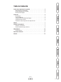
Instrucciones importantes de seguridad . . . . . . . . . . . . . . . . . . . . . . . . . 2
Orientación para el Propietario . . . . . . . . . . . . . . . . . . . . . . . . . . . . . . . . . . 3
Responsabilidades del Instalador . . . . . . . . . . . . . . . . . . . . . . . . . . . . . . . . 3
Descripción del Equipo . . . . . . . . . . . . . . . . . . . . . . . . . . . . . . . . . . . . . . . . 3
Instalacion . . . . . . . . . . . . . . . . . . . . . . . . . . . . . . . . . . . . . . . . . . . . . 4
Desempaque . . . . . . . . . . . . . . . . . . . . . . . . . . . . . . . . . . . . . . . . . . . . . . . . 4
Pautas de Montaje . . . . . . . . . . . . . . . . . . . . . . . . . . . . . . . . . . . . . . . . . . . . 4
Interconexiones de Cableado de Energía . . . . . . . . . . . . . . . . . . . . . . . . . . . 5
Configuración del Sistema. . . . . . . . . . . . . . . . . . . . . . . . . . . . . . . . . . . . . . 6
Prueba del sistema de gestión de energía eléctrica . . . . . . . . . . . . . . . . . . . 7
Mandos. . . . . . . . . . . . . . . . . . . . . . . . . . . . . . . . . . . . . . . . . . . . . . . . 7
Sistema Funcionamiento . . . . . . . . . . . . . . . . . . . . . . . . . . . . . . . . . . . . 7
Alambrar la calcomanía . . . . . . . . . . . . . . . . . . . . . . . . . . . . . . . . . . . . . . . . 8
Hoja de trabajo de cargas eléctricas . . . . . . . . . . . . . . . . . . . . . . . . . . . . . . 9
Mantenimiento . . . . . . . . . . . . . . . . . . . . . . . . . . . . . . . . . . . . . . . . . . 10
Especificaciones. . . . . . . . . . . . . . . . . . . . . . . . . . . . . . . . . . . . . . . . . . . . . 10
Reparacion de Averias . . . . . . . . . . . . . . . . . . . . . . . . . . . . . . . . . . . . 11
Garantia . . . . . . . . . . . . . . . . . . . . . . . . . . . . . . . . . . . . . . . . . . . . . . 12
Tabla de Contenido

2 BRIGGSandSTRATTON.COM
Instrucciones importantes de
seguridad
Éste es el símbolo de alerta de seguridad. Sirve
para advertir al usuario de un posible riesgo para
su integridad física. Siga todos los mensajes de
seguridad que figuren después de este símbolo
para evitar lesiones o incluso la muerte.
El símbolo de alerta de seguridad ( ) se utiliza con una
palabra de señalización (PELIGRO, PRECAUCIÓN,
ADVERTENCIA), una imagen y/o un mensaje de seguridad
para advertir al usuario de un riesgo. PELIGRO indica un
riesgo que, de no evitarse, provocará la muerte o lesiones de
gravedad. ADVERTENCIA indica un riesgo que, de no
evitarse, puede provocar la muerte o lesiones de gravedad.
PRECAUCIÓN indica un riesgo que, de no evitarse, puede
provocar lesiones moderadas. Cuando se utiliza sin el
símbolo de alerta, AVISO indica una situación que podría
producir daños en el equipo. Siga en todo momento los
mensajes de seguridad para evitar o reducir el riesgo de
lesiones y de muerte.
El fabricante no puede prever todas las posibles
circunstancias que pueden implicar riesgos. Por lo tanto, las
advertencias que aparecen en este manual y las etiquetas y
calcomanías adheridas a la unidad no incluyen todas las
posibilidades. Si aplica un procedimiento, método de trabajo
o técnica de operación no recomendada específicamente por
el fabricante, debe estar seguro de que se trata de una
práctica segura para usted y para otras personas. También
debe asegurarse de que el procedimiento, método de trabajo
o técnica de operación que elija, no haga que el sistema de
gestión de energía eléctrica se torne inseguro.
Conserve estas instrucciones
ADVERTENCIA
Únicamente los electricistas capacitados pueden intentar
instalar este sistema. Dicha instalación debe cumplir
estrictamente con los códigos, las regulaciones y las
normas correspondientes.
• Si no se respeta esta indicación pueden producirse lesiones,
daños y/o fallos de funcionamiento del equipo.
ADVERTENCIA
Los cables de baja tensión no se pueden instalar
en el mismo conducto que los cables de
suministro de energía.
• No toque los alambres pelados o receptáculos.
• No use un sistema de gestión de energía eléctrica con cables
eléctricos que estén malgastados, rotos, pelados o dañados de
cualquier forma.
• No maneje el cables eléctricos mientras esté parado en agua,
descalzo o cuando las manos y los pies estén mojados.
• Si fuera necesario realizar trabajos en cercanías de la unidad
mientras está en funcionamiento, párese sobre una superficie
seca y aislada para reducir los riesgos de una descarga.
• No permita que personas descalificadas o niños operen o sirvan
al sistema de gestión de energía eléctrica.
• En caso de que se produzca un accidente causado por una
descarga eléctrica, cierre inmediatamente la fuente de energía
eléctrica y contacta administración local. Evite el contacto
directo con la víctima.
ADVERTENCIA
Si no hace tierra apropiadamente con un sistema
de gestión de energía eléctrica, puede hacer que
ocurra un electrocutamiento.
• A pesar del diseño seguro del sistema de gestión de energía
eléctrica, si se opera este equipo en forma imprudente, si no se
cumple con el mantenimiento o si se actúa con descuido, se
pueden producir lesiones o la muerte.
ADVERTENCIA
El sistema de gestión de energía eléctrica contiene
alta tensión que puede provocar lesiones o la
muerte.
• Use el sistema de gestión de energía eléctrica solamente con la
finalidad para el cual fue diseñado.
• Si usted tiene alguna pregunta acerca de las finalidades de uso
del generador, pregúntele a su concesionario o contacte a Briggs
& Stratton.
• NO exponga al sistema de gestión de energía eléctrica a una
humedad excesiva, polvo, suciedad o vapores corrosivos.
• Permanezca siempre alerta cuando trabaje con este equipo.
NUNCA trabaje con este equipo si se siente cansado física o
mentalmente.
• Si se calientan excesivamente los dispositivos conectados,
apáguelos y abra sus interruptores o quite sus fusibles.
AVISO
El tratamiento inadecuado del sistema de gestión de
energía eléctrica puede dañarlo y acortar su vida
productiva.
La page charge ...
La page charge ...
La page charge ...
La page charge ...
La page charge ...
La page charge ...
La page charge ...
La page charge ...
La page charge ...
La page charge ...
La page charge ...
La page charge ...
La page charge ...
La page charge ...
La page charge ...
La page charge ...
La page charge ...
La page charge ...
La page charge ...
La page charge ...
La page charge ...
La page charge ...
La page charge ...
La page charge ...
-
 1
1
-
 2
2
-
 3
3
-
 4
4
-
 5
5
-
 6
6
-
 7
7
-
 8
8
-
 9
9
-
 10
10
-
 11
11
-
 12
12
-
 13
13
-
 14
14
-
 15
15
-
 16
16
-
 17
17
-
 18
18
-
 19
19
-
 20
20
-
 21
21
-
 22
22
-
 23
23
-
 24
24
-
 25
25
-
 26
26
-
 27
27
-
 28
28
-
 29
29
-
 30
30
-
 31
31
-
 32
32
-
 33
33
-
 34
34
-
 35
35
-
 36
36
-
 37
37
-
 38
38
-
 39
39
-
 40
40
-
 41
41
-
 42
42
-
 43
43
-
 44
44


Simplicity 071035-00 Manuel utilisateur
- Catégorie
- Groupes électrogènes
- Taper
- Manuel utilisateur
dans d''autres langues
- English: Simplicity 071035-00 User manual
- español: Simplicity 071035-00 Manual de usuario
Documents connexes
-
Briggs & Stratton 071013-0 Manuel utilisateur
-
Simplicity INSTALL/OPERATOR'S MANUAL POWER MANAGER W/WHIP MODEL: 071042-0 Manuel utilisateur
-
-
-
-
-
Simplicity 040380-00 Manuel utilisateur