Essentials ZSA-E30CB Le manuel du propriétaire
- Catégorie
- Hottes
- Taper
- Le manuel du propriétaire

Use, Care, and Installation Guide
Model number:
Serial Number:
www.zephyronline.com
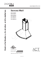
Savona Wall
ZSA-E30CB
ZSA-E30CS
ZSA-E30CW
ZSA-M90CB
ZSA-M90CS
ZSA-M90CW
FEB14.0201 © 2014 Zephyr Corporation
www.goedekers.com

www.zephyronline.com
www.goedekers.com

1
SAFETY NOTICE ................................................................. 2-3
LIST OF MATERIALS ....................................................... 4
INSTALLATION
Ducting Calculation Sheet
....................................... 5
Mounting Height & Clearance
................................ 6
Ducting Options
........................................................... 7
Hood Specifi cations
................................................... 8
Mounting the Hood
..................................................... 9
Ductless Recirculating
.............................................. 10
FEATURES & CONTROLS
ICON Touch Controls
................................................ 11-12
MAINTENANCE
Hood and Filter Cleaning
......................................... 13
Light Bulbs
..................................................................... 14
TROUBLESHOOTING
................................................................ 15
WIRING DIAGRAMS
................................................................... 16
FAN CURVE DIAGRAMS
......................................................... 17-18
LIST OF PARTS AND ACCESSORIES
.............................. 19
Table of Contents
www.goedekers.com

Important Safety Notice
READ AND SAVE THESE INSTRUCTIONS
2
www.zephyronline.com
WARNING
TO REDUCE THE RISK OF FIRE OR ELECTRIC SHOCK, DO NOT USE THIS FAN WITH ANY SOLID-STATE CONTROL DEVICE.
WARNING
TO REDUCE THE RISK OF FIRE ELECTRIC SHOCK, OR INJURY TO PERSONS, OBSERVE THE FOLLOWING:
a. Use this unit only in the manner intended by the manufacturer, if you have questions, contact the manufacturer.
b. Before servicing or cleaning unit, switch power off at service panel and lock panel to prevent power from being switched on accidentally.
When the service disconnecting means cannot be locked, securely fasten a prominent warning device, such as a tag, to the service
panel.
CAUTION
For general ventilating use only. Do not use to exhaust hazardous or explosive materials and vapors. Take care when using cleaning
agents or detergents. Suitable for use in household cooking area.
WARNING
TO REDUCE THE RISK OF RANGE TOP GREASE FIRE:
a. Never leave surface units unattended at high settings. Boilovers cause smoking and greasy spillovers that may ignite. Heat oils slowly
on low or medium settings.
b. Always turn hood ON when cooking at high heat or when fl aming food
c. Clean ventilating fans frequently. Grease should not be allowed to accumulate on fan or fi lter.
d. Use proper pan size. Always use cookware appropriate for the size of the surface element.
e. Keep fan, fi lters and grease laden surfaces clean.
f. Use high setting on hood only when necessary.
g. Don’t leave hood unattended when cooking.
h. Always use cookware and utensils appropriate for the type of and amount of food being prepared.
WARNING
TO REDUCE THE RISK OF INJURY TO PERSONS IN THE EVENT OF A RANGE TOP FIRE, OBSERVE THE FOLLOWING:
a. SMOTHER FLAMES with a close-fi tting lid, cookie sheet, or metal tray, then turn off the burner. BE CAREFUL TO PREVENT BURNS.
If the fl ames do not go out immediately, EVACUATE AND CALL THE FIRE DEPARTMENT.
b. NEVER PICK UP A FLAMING PAN – You may be burned.
c. DO NOT USE WATER, including wet dishcloths or towels – a violent steam explosion will result.
d. Use an extinguisher ONLY if:
1. You know you have a Class ABC extinguisher, and you already know how to operate it.
2. The fi re is small and contained in the area where it started.
3. The fi re department is being called.
4. You can fi ght the fi re with your back to an exit
WARNING
TO REDUCE THE RISK OF FIRE, ELECTRIC SHOCK OR INJURY TO PERSONS, OBSERVE THE FOLLOWING:
a. Installation work and electrical wiring must be done by qualifi ed person(s) in accordance with all applicable codes and standards.
Including fi re-rated construction.
b. Suffi cient air is needed for power combustion and exhausting of gases through the fl ue (chimney) of fuel burning equipment to prevent
back-drafting. Follow the heating equipment manufacturer’s guideline and safety standards such as those published by the National
Fire Protection Association (NFPA) and the American Society for Heating, Refrigeration and Air Conditioning Engineers (ASHRAE) and
the local code authorities.
c. When cutting or drilling into wall or ceiling, do not damage electrical wiring and other hidden utilities.
d. Ducted fans must always vent to the outdoors.
e. NEVER place a switch where it can be reached from a tub or shower.
f. Make sure the power is off before installing, wiring or maintenancing.
www.goedekers.com

Important Safety Notice
3
WARNING
TO REDUCE THE RISK OF FIRE, USE ONLY METAL DUCTWORK.
CAUTION
To reduce risk of fi re and to properly exhaust air outside - Do not vent exhaust air into spaces within walls, ceilings,
attics, crawl spaces or garages.
Not for use over an outdoor grill.
OPERATION
Always leave safety grilles and fi lters in place. Without these components, operating blowers could catch onto hair, fi ngers
and loose clothing.
The manufacturer declines all responsibility in the event of failure to observe the instructions given here for installation,
maintenance and suitable use of the product. The manufacturer further declines all responsibility for injury due to
negligence and the warranty of the unit automatically expires due to improper maintenance.
*NOTE: Please check www.zephyronline.com for revisions before doing any custom work.
ELECTRICAL REQUIREMENTS
Important:
Observe all governing codes and ordinances.
It is the customer’s responsibility:
- To contact a qualifi ed electrical installer.
- To assure that the electrical installation is adequate and in conformance with National Electrical Code, ANSI/NFPA 70
latest edition* or CSA standards C22.1-94, Canadian Electrical Code, Part 1 and C22.2 No.0-M91 - latest edition** and
all local codes and ordinances.
If codes permit and a separate ground wire is used, it is recommended that a qualifi ed electrician determine that the
ground path is adequate.
Do not ground to a gas pipe.
Check with a qualifi ed electrician if you are not sure the range hood is properly grounded.
Do not have a fuse in the neutral or ground circuit.
*National Fire Protection Association Batterymarch Park, Quincy, Massachusetts 02269
** CSA International 8501 East Pleasant Valley Road, Cleveland, Ohio 44131-5575
This appliance requires a 120V 60Hz electrical supply and connected to an individual properly grounded branch circuit
protected by a 15 or 20 ampere circuit breaker or time delay fuse. Wiring must be 2 wire with ground. Please also refer to
Electrical Diagram on product.
A cable locking connector (not supplied) might also be required by local codes. Check with local requirements, purchase
and install appropriate connector if necessary.
www.goedekers.com

4
www.zephyronline.com
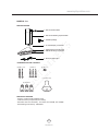
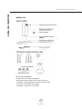
(3) Wire Nuts
(2) M4 x 1-1/2”
(3) M4 x 1”
(2) M4 x 8
PARTS NOT SUPPLIED
- Ducting, conduit and all installation tools
- Cable connector (if required by local codes)
- Extension duct cover accessory - Z1C-01SA, Z1C-01SAB, Z1C-01SAW
- Recirculating kit accessory - ZRC-00SV
HARDWARE PACKAGE CONTENTS
MODELS:
(1) Suction Cup
1 - Hood body with internal blower
2 - Aluminum mesh filters
1 - Duct cover assembly, top and bottom
1 - Duct cover wall bracket
2 - 50W GU-10 halogen light bulbs
1 - 6” round damper, pre-installed
1 - Hardware package
PARTS SUPPLIED
ZSA
www.goedekers.com

5
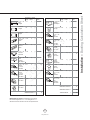
Duct pieces
To t a l
Equivalent number
length x used =
3- 1/ 4” x 10”
Rect.,
straight
1 Ft. x ( ) =
Ft.
8” Round,
straight
1 Ft. x ( ) =
Ft.
3- 1/ 4” x 10”
Rect. 90
0
elbow
15 Ft. x ( ) =
Ft.
3- 1/ 4” x 10”
Rect. 45
0
elbow
9 Ft. x ( ) =
Ft.
3- 1/ 4” x 10”
Rect. 90
0
flat elbow
24 Ft. x ( ) =
Ft.
3- 1/ 4” x 10”
Rect.
wall cap
with damper
30 Ft. x ( ) =
Ft.
3- 1/ 4” x 10”
Rect. to
6” round
transition
5 Ft. x ( ) =
Ft.
3- 1/ 4” x 10”
Rect. to
6” round
transition
90
0
elbow
20 Ft. x ( ) =
Ft.
6” Round,
90
0
elbow
15 Ft. x ( ) =
Ft.
6” Round,
45
0
elbow
9 Ft. x ( ) =
Ft.
Ft.
7” Round,
straight
1 Ft. x ( ) =
Ft.
Subtotal column 1 =
Duct pieces
To t a l
Equivalent number
length x used =
6”- 8” Round
wall cap
with damper
30 Ft. x ( ) =
Ft.
Round
wall cap
with damper
30 Ft. x ( ) =
Ft.
7” or 8”
Round,
90
0
elbow
15 Ft. x ( ) =
Ft.
7” or 8”
7” or 8”
Round,
45
0
elbow
9 Ft. x ( ) =
Ft.
Ft.
Ft.
Ft.
6”- 8” Round,
roof cap
30 Ft. x ( ) =
Ft.
7” or 8”
Round,
roof cap
30 Ft. x ( ) =
Ft.
Subtotal column 2 =
Subtotal column 1 =
Total ductwork =
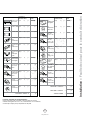
Maximum Duct Length: For satisfactory air movement,
the total duct length of a 3 1/ 4” x 10” rectangular 6” or 7”
diameter round duct should not exceed 100 equivalent feet.
6” round to
3- 1/ 4” x 10”
rect.
transition
1 Ft. x ( ) =
Ft.
6” round to
3- 1/ 4” x 10”
rect.
transition
90
0
elbow
16 Ft. x ( ) =
Ft.
7” round to
3 1/ 4” x 10”
rect.
transition
8 Ft. x ( ) =
Ft.
7” round to
3- 1/ 4” x 10”
rect.
transition
90
0
elbow
23 Ft. x ( ) =
Ft.
Installation – Ducting Calculation Sheet
www.goedekers.com

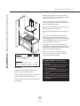
Installation – Mounting Height & Clearance
6
www.zephyronline.com
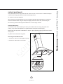
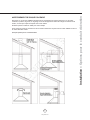
DUCTING
A minimum of 6” round duct must be used to
maintain maximum air fl ow effi ciency.
Always use rigid type metal ducts only. Flexible
ducts could restrict air fl ow by up to 50%.
Use calculation worksheet to compute total duct
work (Page 5).
ALWAYS, when possible, reduce the number of
transitions and turns. If a long duct run is required,
increase duct size from 6” to 7” or 8”.
If turns or transitions are required: Install as far
away from duct opening and as far apart between
the two transitions as possible.
Minimum mount height between range top to hood
bottom should be no less than 26”.
Maximum mount height should be no higher than
34”.
It is important to install the hood at the proper
mounting height. Hoods mounted too low could
result in heat damage and fi re hazard; while hoods
mounted too high will be hard to reach and will
loose performance and effi ciency.
If available, also refer to range manufacturer’s
height clearance requirements and recommended
hood mounting height above range. Always check
your local codes for any differences.
Duct cover extension kit available for ceiling
heights up to 12 feet. Turn to page 19 for part
number and ordering information.
DAMAGE-SHIPMENT / INSTALLATION:
•
Please fully inspect unit for damage before
installation.
•
If the unit is damaged in shipment, return the
unit to the store in which it was bought for
repair or replacement.
• If the unit is damaged by the customer, repair
or replacement is the responsibility of the
customer.
• If the unit is damaged by the installer (if other
than the customer), repair of replacement must
be made by arrangement between customer
and installer.
26” min.
34” max.
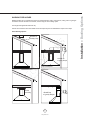
min. A
min. B
max. C
min. D
min. E
max. F
Standard Extension
Hood Heights Duct Cover Duct Cover
minimum ducted (A) 28” 45-
1/2“
minimum recirculating (B) 32” 50“
maximum (C) 45” 80”
Ceiling Heights
minimum ducted (D) 90” (7’ 6”) 107-
1/2“ (9‘)
minimum recirculating (E) 94” (7’ 10”) 112“ (9‘ 4”)
maximum (F) 115” (9’ 7“) 150” (12’ 6”)
36”
www.goedekers.com

7
WARNING FIRE HAZARD
NEVER exhaust air or terminate duct work into spaces between walls, crawl spaces, ceiling, attics or garages.
All exhaust must be ducted to the outside, unless using the recirculating option.
Use single wall rigid metal ductwork only.
Fasten all connections with sheet metal screws and tape all joints w/ certifi ed Silver Tape or Duct Tape.
Some Ducting Options
Installation – Ducting Options
side wall cap
w/ gravity damper
Soffit or crawl space
Roof Pitch w/
Flashing & Cap
ductless
recirculating
side wall cap
w/ gravity damper
www.goedekers.com

8
www.zephyronline.com
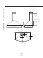
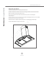
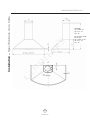
Installation – Hood Specifi cation
4"
6
"
CL
1”
9”
1”
29 15/16”, 35 7/16”
7
1
/2”
19
1/2”
11”
STANDARD
min. ducted - 28”
min. recirc. - 32”
max. - 45”
Z1C-01SA, Z1C-01SAB
Z1C-01SAW
EXTENSIONS
min. ducted - 45
1/2”
min. recirc. - 50”
max. - 80”
1/2”
www.goedekers.com

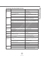
9
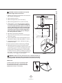
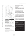
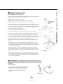
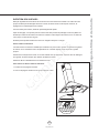
1. Measure from range top to hood bottom and mark line A.
(26” minimum from range top) .
2. Plum and mark center line.
3. Mark hood height line B. (9-1/2” from line A)
4. Mark mounting spread from C/L. (9-7/8” on line B)
5. Fasten (2) M4 x 1-1/2” screws into studs on line B but
do not tighten all the way. Note: Wood blocking may
need to be added behind the drywall if no studs are
present. Wall anchors may also be used but check
local codes for compliance. Failure to use suitable
wall anchors and screws to hold the weight of the
hood could result in personal injury or damage to
the cooking surface or counter.
6. Remove the (2) aluminum mesh fi lters.
7. Hang hood onto the mounting screws and hand tighten
each screw. (Fig A)
8. Center and attach duct cover mounting bracket to wall
just below the ceiling or soffi t using (2) M4 x 1” screws.
9. Install electrical and duct work. Seal duct work with
aluminum duct tape.
10. Power up hood and check for leaks around duct tape.
11. Place telescopic duct covers onto hood and extend
inner (top) duct cover upwards and secure to duct cover
bracket using (2) M4 x 8 screws. Reinstall mesh fi lters.
* If using hood in recirculating mode you must secure the
air diverter plate onto wall before installing duct work and
duct covers. You will also need to install charcoal fi lters
and brackets. Turn to page 10 for more details.
9-7/8”
9-
1/2
”
26” min.
6-
1/2
”
CAUTION: At least two installers are required
due to the weight and size of the hood.
!
WARNING: Electrical wiring must be done by a qualified person(s) in
accordance with all applicable codes and standards. This range hood must be
properly grounded. Turn off electrical power at service entrance before wiring.
!
Cable Lock
Cable Lock
A cable locking connector (not supplied) might
be required by local codes. Check with local
requirements and codes, purchase and install
appropriate connector if necessary.
Installation – Mounting the Hood
FIG. A
www.goedekers.com

10
www.zephyronline.com
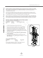
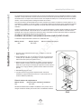
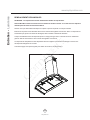
Ductless recirculation is intended for applications where an exhaust duct work is not possible to be installed.
When converted, the hood functions as a recirculating hood rather than an exhaust hood. Fumes and exhaust
from cooking are drawn and fi ltered by a set of optional charcoal fi lters. The air is then purifi ed and re-
circulated back within the home.
We recommend to ALWAYS exhaust air outside of the home by employing existing or installing new duct
work, if possible. The hood is most effective and effi cient as an exhaust hood. Only when the exhaust option
is not possible should you recourse to converting the hood into a recirculating hood.
When converted to be a recirculating hood, a set of charcoal fi lters are required on top of its standard mesh
fi lter set. Order according to its part number below. The standard mesh fi lters are intended to capture residue
from cooking and the optional charcoal fi lters help to purify fumes exhausted from cooking for re-circulation.
RECIRCULATING KIT (REQUIRED IF NO DUCTING IS USED)
Kit includes charcoal fi lters and air diverter plate.
Hood Models Part No. Filters & Brackets in pkg.
ZSA ZRC-00SV 2
1. Purchase recirculating kit per the part number above
2. Secure air diverter plate to wall below duct cover bracket. Run 6”
ducting from top of hood and secure to air diverter plate. (FIG. B)
3. Remove aluminum mesh fi lters from hood. Secure charcoal fi lter
brackets to the hood body behind each mesh fi lters using the screws
included in the recirculating kit. Clip charcoal fi lters onto each charcoal
fi lter bracket. (FIG. B)
4. Re-Install mesh fi lters. For more details refer to manual included
with recirculating kit.
5. Charcoal fi lters must be replaced after every 120 hours of use (or
approximately every 3 to 4 months based on an average of 1 - 2 hrs. of
daily cooking time).
Charcoal Filter Replacements
Hood Model Part No. Qty to Order
ZSA Z0F-C002 2
DO NOT WASH CHARCOAL FILTERS. Charcoal fi lters may need
to be changed more often depending on cooking habits.
Installation – Ductless Recirculating
FIG. B
www.goedekers.com

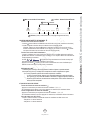
11
Lights On/Dim/Off
Display (speed level, delay off, filter clean/change)
Adjust 5 Speed Levels
Power / Delay Off
1 POWER / DELAY OFF BUTTON
Power Button Function
- Button will turn power on and off for entire hood (fan and lights).
- Hood will remember the last speed and light level it was turned off at.
(Example: Press Button to turn off hood when on fan speed 4 and high lights. Press Button
again and the hood will turn back on at speed 4 and high lights level.)
Delay Off Button Function
- With the fan on press and hold the Button for two seconds. The fan will change to speed 1 and the
5 minute delay off timer will start.
+ LEDs will illuminate and slowly blink in accordance with the time
remaining until the fan and lights automatically turn off.
- Pressing Button while Delay Off Function is enabled will turn the hood off and cancel the Delay Off
Function.
ACT Verification
- Airflow Control Technology (ACT) allows the installer to set the maximum fan CFM to align with local
codes and regulations.
- To verify the maximum fan CFM:
- With hood off, hold the Button for two seconds. If all five fan speed indicators illuminate =
default maximum CFM. If four fan speed indicators illuminate = 390 maximum CFM. If 3 fan
speed indicators illuminate = 290 maximum CFM.
2 SPEED SELECTION BUTTON
Fan Speed Decrease Button
- Press this button to decrease fan speed. 5, 4, 3, 2, 1.
- If fan is On Speed 1 and this button is pressed, fan will power Off.
Fan Speed Increase Button
- Press this button to increase fan speed. Fan On, 1, 2, 3, 4, 5.
- If hood is Off and this button is pressed, fan will turn On Speed 1.
Act Enabled Speed Selections
- When ACT is enabled, the number of fan speeds will be reduced as follows:
- 390 CFM = Maximum 4 speeds
- 290 CFM = Maximum 3 speeds
Features & Controls - ICON Touch Controls
www.goedekers.com

12
www.zephyronline.com
Features & Controls - ICON Touch Controls
3 LIGHTS BUTTON
- Lights are two levels, High and Low.
- From off, press one time for High. Press again for Low. Press again to power lights off.
4 DISPLAY INDICATORS
Mesh Filter Clean Reminder (always enabled)
- After 30 hours of fan usage, the button indicator will begin to slowly blink indicating it is time to
clean the mesh filters.
- To reset: With hood off: hold the button for three seconds. All LED indicators will blink two times
confirming the 30 hour timer has been reset.
Charcoal Filter Replace Indicator (disabled by default, must be enabled if recirculating hood)
- To enable Charcoal Filter Replacement Reminder:
- With hood off, hold button and button simultaneously for two seconds. All LED indicators
will illuminate for three seconds confirming the Charcoal Filter Replace Reminder is enabled.
- To disable Charcoal Filter Replacement Reminder:
- With hood off, hold button and button simultaneously for two seconds. All LED indicators
will blink two times confirming the Charcoal Filter Replace Reminder is disabled.
- After 120 hours of fan usage the button will slowly blink indicating the charcoal filters need
replacment.
- To reset: With hood off, hold the button for two seconds. All LED indicators will blink two times
confirming the 120 hour timer has been reset.
www.goedekers.com

13
SURFACE MAINTENANCE:
Clean periodically with hot soapy water and clean cotton cloth. Do not use corrosive or abrasive detergent
or steel wool/scouring pads which will scratch and damage surface.
For heavier soil use liquid degreaser.
After cleaning it is recommended that you use non-abrasive stainless steel polish/cleaners, to polish and
buff out the stainless luster and grain. Always scrub lightly, with clean cotton cloth, and with the grain.
Do not use any product containing chlorine bleach. Do not use “orange” cleaners.
Aluminum Mesh Filters
The aluminum mesh fi lters installed by the factory are intended to fi lter out residue and grease from
cooking. They need not be replaced on a regular basis but are required to be kept clean.
Remove and clean by hand or in dishwasher on low heat. Spray degreasing detergent and leave to soak if
heavily soiled.
Dry fi lters and re-install before using hood.
Removing Aluminum Mesh Filters
1. Pull down on fi lter latch to disengage the springs
2. Pull down on fi lter hande to remove fi lter
Maintenance – Hood and Filter Cleaning
www.goedekers.com

14
www.zephyronline.com
REPLACING LIGHT BULBS
CAUTION: Light bulb becomes extremely hot when turned on.
DO NOT touch bulb until switched off and cooled. Touching hot bulbs could cause serious burns.
Make sure all power is turned off and bulbs are not hot.
Remove by turning bulb counter clockwise. Note: Bulb does not unscrew; it turns 60 degrees,
stops and falls out.
If bulbs are diffi cult to turn due to prolonged use, fi rmly attach the included glass suction cup or use a rubber/
latex glove grip and turn the bulb counter clockwise.
Replacement bulbs are available at specialty lighting stores. Purchase type GU-10 50W halogen.
For part numbers please turn to page 19 of the manual.
Maintenance – Light Bulbs
www.goedekers.com

15
Troubleshooting
TROUBLESHOOTING PROCEDURES FOR ZSA
Issue Cause What to do
After installation,
the unit doesn’t
work.
1. The power source is not turned ON. 1. Make sure the circuit breaker and the unit’s
power is ON.
2. The power line and the cable locking connector
is not connecting properly.
2. Check the power connection with the unit is
connected properly.
3. The switch board and control board wirings are
disconnected.
3. Make sure the wirings between the switch
board and control board are connected
properly.
4. The switch board or control board is defective. 4. Change the switch board or control board.
Light works, but
blower is not
turning.
1. The blower cable is disconnected. 1. Check all wiring from the blower to be sure all
cables are connected properly.
2. The blower is defective, possibly seized. 2. Change the blower.
3. The thermally protected system detects if the
blower is too hot to operate and shuts the blower
down.
3. The blower will function properly after the
thermally protected system cool down.
4. Damaged capacitor. 4. Change the capacitor.
5. The switch board or control board is defective. 5. Change the switch board or control board.
The unit is
vibrating.
1. The blower is not secured in place. 1. Tighten the blower in place.
2. Damaged blower wheel. 2. Replace the blower.
3. The hood is not secured in place. 3. Check the installation of the hood.
The blower is
working, but the
lights are not.
1. The light socket connector is loose or
disconnected.
1. Check the light socket connector to be sure it
is pluged in properly.
2. Defective halogen bulb. 2. Change the halogen bulb.
3. The light bulb is loose. 3. Tighten the light bulb.
The speed levels
sound the same.
1. Using the wong size of ducting. 1. Change the duct pipe size to at least 6” round
or higher.
The unit turns on
by itself.
1. A spot light or kitchen lamp is shining directly
onto the switch controls.
1. The switch controls are light sensative. A
direct light source onto the switch controls
may disrupt switch functions.
The unit is
whistling.
1. The duct pipe connections are not sealed or
connected properly.
1. Check the duct pipe connections to be sure all
connections are sealed properly.
The hood is
not venting out
properly.
1. The hood might be hanging to high from the
cook top.
1. Adjust the distance between the cook top and
the bottom of the hood within 26” and 34”
range.
2. The wind from the opened windows or opened
doors in the surrounding area are affecting the
ventilation of the hood.
2. Close all the windows and doors to eliminate
the outside wind fl ow.
3. Blockage in the duct opening or ductwork. 3. Remove all the blocking from the duct work or
duct opening.
4. The direction of duct opening is against the wind. 4. Adjust the duct opening direction.
5. Using the wrong size of ducting. 5. Change the ducting to at least 6” or higher.
Mesh Filter is
vibrating.
1. Mesh fi lter is loose. 1. Change the mesh fi lter.
2. Filter spring clip is loose or broken. 2. Uninstall and reinstall fi lter, push up on fi lter
latch. Replace mesh fi lter if needed.
www.goedekers.com

16
www.zephyronline.com
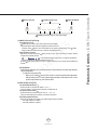
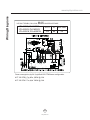
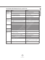
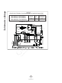
Wiring Diagrams
VOLTS
HZ
MAX AMPS
120 60 3.5
USE ONLY TYPE MR16, GU10, 50 W. MAX. HALOGEN LIGHT BULBS.
ZSA-E30CS, ZSA-M90CS
ZSA-E30CB, ZSA-M90CB
ZSA-E30CW, ZSA-M90CW
Power consumption shown for default 685 CFM blower confi guration
ACT 390 CFM - Fan Max. 300W @ 2.6A
ACT 290 CFM - Fan Max. 289W @ 2.4A
www.goedekers.com

17
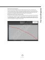
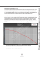
Fan Curve Diagrams
Airfl ow Control Technology (ACT)
Some local codes limit the maximum amount of CFM a range hood can move. ACT allows you to
control the maximum blower CFM of hoods with of select Zephyr Ventilation range hoods without the
need for expensive make up air kits. ACT enables the installer to easily set the maximum blower speed
to one of two most commonly specifi ed CFM levels; 390 or 290 CFM. The usage of ACT may not be
necessary for your installation. Please check your local codes for CFM restrictions.
By default the maximum blower CFM is set to 685.
To verify if your installer enabled ACT; With hood off, press and hold the power button for three seconds.
If 5 LEDs illuminate = default max. CFM, if 4 LEDs illuminate = max. 390 CFM, and if 3 LEDs illuminate
= max. 290 CFM. When ACT is enabled, the number of blower speeds will be reduced. 390 CFM = max.
3 speeds and 290 CFM = max. 2 speeds. There should also be a foil label located inside the hood body
near the wiring diagram that indicates the blower CFM.
www.goedekers.com

www.zephyronline.com
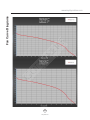
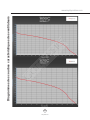
Fan Curve Diagrams
18
www.goedekers.com
La page charge ...
La page charge ...
La page charge ...
La page charge ...
La page charge ...
La page charge ...
La page charge ...
La page charge ...
La page charge ...
La page charge ...
La page charge ...
La page charge ...
La page charge ...
La page charge ...
La page charge ...
La page charge ...
La page charge ...
La page charge ...
La page charge ...
La page charge ...
La page charge ...
La page charge ...
La page charge ...
La page charge ...
-
 1
1
-
 2
2
-
 3
3
-
 4
4
-
 5
5
-
 6
6
-
 7
7
-
 8
8
-
 9
9
-
 10
10
-
 11
11
-
 12
12
-
 13
13
-
 14
14
-
 15
15
-
 16
16
-
 17
17
-
 18
18
-
 19
19
-
 20
20
-
 21
21
-
 22
22
-
 23
23
-
 24
24
-
 25
25
-
 26
26
-
 27
27
-
 28
28
-
 29
29
-
 30
30
-
 31
31
-
 32
32
-
 33
33
-
 34
34
-
 35
35
-
 36
36
-
 37
37
-
 38
38
-
 39
39
-
 40
40
-
 41
41
-
 42
42
-
 43
43
-
 44
44


Essentials ZSA-E30CB Le manuel du propriétaire
- Catégorie
- Hottes
- Taper
- Le manuel du propriétaire
dans d''autres langues
- English: Essentials ZSA-E30CB Owner's manual
Autres documents
-
Zephyr ZSA-E30CW Le manuel du propriétaire
-
-
-
-
-
XO XOS36S Le manuel du propriétaire
-
GE PVWC930 Owner's Manual and Installation Instructions
-
-
-