Jenn-Air JGCP436 Guide d'installation

Taper
Guide d'installation

Ce manuel convient également à

_]ENN-AIRo
INSTALLATIONINSTRUCTIONS
30" (76.2 CM), 36" (91.4 CM) AND 48" (121.9 CM)
COMMERCIAL STYLEGAS COOl(TOPS
INSTRUCTIONSD'INSTALLATION- TABLESDECUISSONA
GAZ DE30" (76,2 CM)_ 36" (91,4 CM) ET48" (121,9 CM)-
MODELECOMMERCIAL
Table of Contents/Table des mati_res
COOKTOP SAFETY ........................................................................ 2
INSTALLATION REQUIREMENTS ................................................ 3
Tools and Parts ............................................................................ 3
Location Requirements ................................................................ 3
Electrical Requirements ............................................................... 5
Gas Supply Requirements ........................................................... 6
INSTALLATION INSTRUCTIONS .................................................. 7
Install Cooktop ............................................................................. 7
Install Optional Backguard ........................................................... 7
Make Gas Connection .................................................................. 7
Install Griddle ................................................................................ 9
Complete Installation .................................................................... 9
GAS CONVERSIONS .................................................................... 11
LP Gas Conversion .................................................................... 11
Natural Gas Conversion ............................................................. 12
WIRING DIAGRAMS ..................................................................... 14
STRIP CIRCUIT ............................................................................. 15
SI_CURITI_ DE LA TABLE DE CUlSSON ............................... 16
EXIGENCES D'INSTALLATION .............................................. 17
Outillage et pieces ................................................................. 17
Exigences d'emplacement .................................................... 18
Specifications electriques ..................................................... 21
Specifications de I'alimentation en gaz ................................ 21
INSTRUCTIONS D'INSTALLATION ....................................... 22
Installation de latable de cuisson ......................................... 22
Installation du dosseret facultatif .......................................... 23
Raccordement au gaz ........................................................... 23
Installation de la plaque a frire .............................................. 24
Achever I'installation ............................................................. 25
CONVERSIONS POUR CHANGEMENT DE GAZ ................. 27
Conversion pour I'alimentation au propane .......................... 27
Conversion pour I'alimentation au gaz naturel ..................... 29
SCHleMA DES CIRCUITS ....................................................... 30
SCHleMA DE CABLAGE .......................................................... 31
IMPORTANT:
installer: Leave installation instructions with the homeowner.
Homeowner: Keep installation instructions for future reference.
IMPORTANT :
Instaliateur : Remettre les instructions d'installation au propri6taire.
Propri6taire : Conserver les instructions d'installation pour r6f@ence ult@ieure.
W10145395A
COOKTOP SAFETY
Your safety and the safety of others are very important.
We have provided many important safety messages in this manual and on your appliance. Always read and obey all safety
messages.
This is the safety alert symbol.
This symbol alerts you to potential hazards that can kill or hurt you and others.
All safety messages will follow the safety alert symbol and either the word "DANGER" or "WARNING."
These words mean:
You can be killed or seriously injured if you don't immediately
follow instructions.
You can be killed or seriously injured if you don't follow
instructions.
All safety messages will tell you what the potential hazard is, tell you how to reduce the chance of injury, and tell you what can
happen if the instructions are not followed.
WARNING: If the information in this manual is not followed exactly, a fire or explosion
may result causing property damage, personal injury or death,
- Do not store or use gasoline or other flammable vapors and liquids in the vicinity of this
or any other appliance,
- WHAT TO DO IF YOU SMELL GAS:
Do not try to light any appliance.
Do not touch any electrical switch.
Do not use any phone in your building.
Immediately call your gas supplier from a neighbor's phone. Follow the gas supplier's
instructions.
If you cannot reach your gas supplier, call the fire department.
- Installation and service must be performed by a qualified installer, service agency or
the gas supplier,
WARNING: Gas leaks cannot always be detected by smell.
Gas suppliers recommend that you use a gas detector approved by UL or CSA.
For more information, contact your gas supplier.
If a gas leak is detected, follow the "What to do if you smell gas" instructions.
In the State of Massachusetts, the following installation instructions apply:
m Installations and repairs must be performed by a qualified or licensed contractor, plumber, or gasfitter qualified or licensed by
the State of Massachusetts.
m If using a ball valve, it shall be a T-handle type.
m A flexible gas connector, when used, must not exceed 3 feet.
2
INSTALLATIONREQUIREMENTS
Gather the required tools and parts before starting installation.
Read and follow the instructions provided with any tools listed
here.
Tools Needed
Adjustable wrench
Tape measure
Marker or pencil
Pipe wrench
Flat-blade screwdriver
18/le"combination wrench
Wrench or pliers
Pipe-joint compound
resistant to LP gas
Noncorrosive leak-
detection solution
For LP/Natural Gas
Conversions
T15 Torx_t screwdriver
Adjustable wrench
3/8"drive ratchet
7/8"socket
1/2"deep-well socket
7 mm nut driver
Masking tape
Parts Supplied
Check that all parts are included.
Gas pressure regulator
Burner grates
Burner heads and caps
Griddle drip tray (on griddle models)
Foam tape
LP orifice package (W10221288)
Conversion label (W10221320)
NOTE: The cooktop is manufactured for use with Natural gas. To
convert to LP gas, see the "Gas Conversions" section.
Optional Backguards
48" (121.9 cm) models must be installed with a backsplash if
installing at zero clearance to a combustible backwall. See
"Cabinet Dimensions" in the "Location Requirements" section for
installation requirements.
36" (91.4 cm) Retractable Backguard
Order Part Number 8284756
48" (121.9 cm) Retractable Backguard
Order Part Number 8284755
9" (22.9 cm) Backguard for 36" (91.4 cm) Cooktops
Order Part Number W10115776
9" (22.9 cm) Backguard for 48" (121.9 cm) Cooktops
Order Part Number W10115777
33W' (85.0 cm) Retractable Backguard with Wire Shelf for
36" (91.4 cm) Cooktops
Order Part Number W10285448
33W' (85.0 cm) Retractable Backguard with Wire Shelf for
48" (121.9 cm) Cooktops
Order Part Number W10285449
To order, see the "Assistance or Service" section of the Use and
Care Guide.
Check local codes and consult gas supplier. Check existing gas
supply and electrical supply. See "Electrical Requirements" and
"Gas Supply Requirements" sections.
High Altitude Conversion
To convert the cooktop for elevations above 6,560 ft (1999.5 m),
order a High Altitude Conversion Kit.
Part Number W10237848 - LP high altitude
Part Number W10160841 - Natural gas high altitude
To order, see the "Assistance or Service" section of the Use and
Care Guide.
IMPORTANT: Observe all governing codes and ordinances. Do
not obstruct flow of combustion and ventilation air.
It is the installer's responsibility to comply with installation
clearances specified on the model/serial rating plate. The
model/serial rating plate is located on the underside of the
cooktop burner base.
It is recommended that a 600 CFM or larger vent hood be
installed above the cooktop.
It is not recommended that a microwave hood combination
be mounted above the cooktop.
The cooktop should be installed in a location away from
strong draft areas, such as windows, doors and strong
heating vents or fans.
All openings in the wall or floor where cooktop is to be
installed must be sealed.
Cabinet opening dimensions that are shown must be used.
Given dimensions are minimum clearances.
Grounded electrical supply is required. See "Electrical
Requirements" section.
Proper gas supply connection must be available. See "Gas
Supply Requirements" section.
The cooktop is designed to hang from the countertop by its
side or rear flanges.
The gas and electric supply should be located as shown in
"Gas and Electric Connection Locations" section so that they
are accessible without requiring removal of the cooktop.
Provide cutout in left rear corner of cutout enclosure as
shown to provide clearance for gas inlet, power supply cord,
and to allow the rating label to be visible.
IMPORTANT: To avoid damage to your cabinets, check with your
builder or cabinet supplier to make sure that the materials used
will not discolor, delaminate or sustain other damage.
Mobile Home - Additional Installation Requirements
The installation of this cooktop must conform to the
Manufactured Home Construction and Safety Standard, Title 24
CFR, Part 3280 (formerly the Federal Standard for Mobile Home
Construction and Safety, Title 24, HUD Part 280). When such
standard is not applicable, use the Standard for Manufactured
Home Installations, ANSI A225.1/NFPA 501A or local codes.
In Canada, the installation of this cooktop must conform with the
current standards CAN/CSA-A240-1atest edition, or with local
codes.
I"®TORX is a registered trademark of Acument Intellectual Properties, LLC.
Product Dimensions
A
B
D
A. 27_" (68.9 cm)
B. 30" (76.2 cm) cooktop: 29 _" (75.1 cm) actual width
36" (91.4 cm) cooktop: 35_" (90.4 cm) actual width
48" (121.9 cm) cooktop: 47_" (120.8 cm) actual width
Side View of Cooktop
A
C. Island trim or optional backguard
D. 36" (91.4 cm) long 3 prong grounding-type power
supply cord
E. Model/serial rating plate (located on the
underside of the cooktop burner base)
A. 273/4"(70.5 cm)
B. 1_" (3.2cm)
C. 7_" (18.8 cm)
D. Gas inlet is located 1_" (4.8 cm) from the back of
the cooktop burner base and 4 _" (12.4 cm) in
from left-hand side of the cooktop burner base.
E. 22" (55.9 cm)
F. 35_ '' (8.4 cm)
G. _" (1.4 cm)
Gas and Electric Connection Locations
B C
A. Grounded 3-prong outlet should be located on
left-hand side of the cutout 16" (40.6 cm) max.
from enclosure sidewall
B. 10" (25.4 cm) min. clearance from countertop to
top of the outlet
C. 14" (35.6 cm) countertop to the gas supply fine
D. Gas supply line should be located in this area on
rear or side walls, or the supply line can come up
through the floor.
NOTE: Solid side and bottom of cutout enclosure
not shown.
Cabinet Requirements
A. See chart.
B. See chart.
C. See chart.
D. See chart.
E. See chart.
F. 18" (45.7 cm) min. clearance upper
cabinet to countertop
G. ¾" (1.9 cm) back of cabinet cutout to gas
opening cutout
H. 6_" (16.1 cm) gas opening cutout depth
I. 127/2'' (31.7 cm) gas opening cutout width
J. 22 ¼" (56.5 cm) cabinet cutout depth
K. 2" (5.1 cm) cabinet side to gas cutout
L. 6" (15.2 cm) min. distance on both sides of the
cooktop to the side wall or other combustible
material above cooking surface
M. 24" (61.0 cm) cabinet depth
N. 7_" (18.4 cm) cabinet depth to countertop
Q. Notch to be equal on both sides
R 13" (33.0 cm) upper cabinet depth
Size Model A** B* C D E
Cooktop Cutout Cooktop to Optional Cabinet and Countertop Only
to Back Wall Cabinet Backguard and Countertop
Upper Cabinet
Opening
30" (76.2 cm) JGCP430 13A"(4.4 cm)** 30" (76.2 cm) 30" (76.2 cm) 291¼'' (74.3 cm) 30" (76.2 cm) or
297/8'' (75.9 cm) for
zero clearance
36" (91.4 cm) JGCP436 13A"(4.4 cm)** 42" (106.7 cm) 36" (91.4 cm) 351¼'' (89.5 cm) 36" (91.4 cm) or
JGCP536 357/8'' (91.1 cm) for
zero clearance
48" (121.9 cm) JGCP548 13A'' (4.4 cm)** 42" (106.7 cm) 48" (121.9 cm) 47W' (120.0 cm) 48" (121.9 cm) or
477/8'' (121.6 cm) for
zero clearance
*NOTES: Dimension "B" can be reduced by 6" (15.2 cm) when bottom of wood or metal cabinet is covered by not less than
0.25" (6.4 mm) flame retardant millboard covered with not less than No. 28 MSG sheet metal, 0.015" (0.4 mm) stainless steel,
0.024" (0.6 mm) aluminum or 0.020" (0.5 mm) copper.
If installing a range hood above the cooktop, follow the range hood instructions for dimensional clearances above the cooktop
surface.
**NOTE: If backwall is constructed of a combustible material and a backguard is not installed, a minimum clearance of dimension
A + 3" (7.6 cm) is required for 36" (91.4 cm) and 48" (121.9 cm) cooktops.
Electrical Shock Hazard
Plug into a grounded 3 prong outlet.
Do not remove ground prong.
Do not use an adapter.
Do not use an extension cord.
Failure to follow these instructions can result in death,
fire, or electrical shock.
IMPORTANT: The cooktop must be electrically grounded in
accordance with local codes and ordinances, or in the absence
of local codes, with the National Electrical Code, ANSI/NFPA 70
or Canadian Electrical Code, CSA C22.1.
This cooktop is equipped with an electronic ignition system that
will not operate if plugged into an outlet that is not properly
polarized.
If codes permit and a separate ground wire is used, it is
recommended that a qualified electrical installer determine that
the ground path is adequate.
A copy of the above code standards can be obtained from:
National Fire Protection Association
One Batterymarch Park
Quincy, MA 02269
CSA International
8501 East Pleasant Valley Road
Cleveland, Ohio 44131-5575
A 120 volt, 60 Hz, AC only, 15-amp, fused electrical circuit is
required. A time-delay fuse or circuit breaker is also
recommended.Itisrecommendedthataseparatecircuit
servingonlythiscooktopbeprovided.
Electronicignitionsystemsoperatewithinwidevoltagelimits,
butpropergroundingandpolarityarenecessary.Checkthat
theoutletprovides120-voltpowerandiscorrectlygrounded.
Thewiringdiagramsareprovidedwiththiscooktop.The
wiringdiagramsarelocatedinsidethecontrolconsoleandin
the"WiringDiagrams"section.
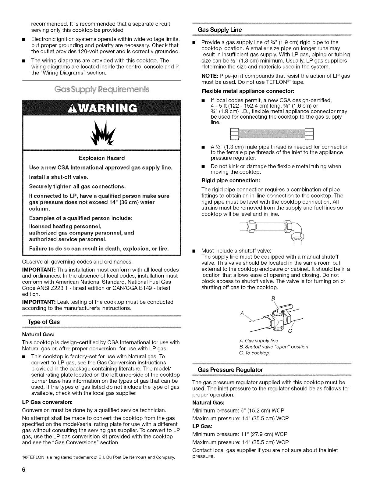
Explosion Hazard
Use a new CSA International approved gas supply line.
Install a shut=off valve.
Securely tighten all gas connections.
if connected to LP, have a qualified person make sure
gas pressure does not exceed 14" (36 cm) water
column.
Examples of a qualified person include:
licensed heating personnel,
authorized gas company personnel, and
authorized service personnel.
Failure to do so can result in death, explosion, or fire.
Observe all governing codes and ordinances.
IMPORTANT: This installation must conform with all local codes
and ordinances. In the absence of local codes, installation must
conform with American National Standard, National Fuel Gas
Code ANSI Z223.1 -latest edition or CAN/CGA B149 -latest
edition.
IMPORTANT: Leak testing of the cooktop must be conducted
according to the manufacturer's instructions.
Type of Gas
Natural Gas:
This cooktop is design-certified by CSA International for use with
Natural gas or, after proper conversion, for use with LP gas.
This cooktop is factory-set for use with Natural gas. To
convert to LP gas, see the Gas Conversion instructions
provided in the package containing literature. The model/
serial rating plate located on the left underside of the cooktop
burner base has information on the types of gas that can be
used. If the types of gas listed do not include the type of gas
available, check with the local gas supplier.
LP Gas conversion:
Conversion must be done by a qualified service technician.
No attempt shall be made to convert the cooktop from the gas
specified on the model/serial rating plate for use with a different
gas without consulting the serving gas supplier. To convert to LP
gas, use the LP gas converision kit provided with the cooktop
and see the "Gas Conversions" section.
t®TEFLON is a registered trademark of E.I. Du Pont De Nemours and Company.
Gas Supply Line
Provide a gas supply line of 3_,,(1.9 cm) rigid pipe to the
cooktop location. A smaller size pipe on longer runs may
result in insufficient gas supply. With LP gas, piping or tubing
size can be V2"(1.3 cm) minimum. Usually, LP gas suppliers
determine the size and materials used in the system.
NOTE: Pipe-joint compounds that resist the action of LP gas
must be used. Do not use TEFLON ®ttape.
Flexible metal appliance connector:
If local codes permit, a new CSA design-certified,
4 - 5 ft (122 - 152.4 cm) long, 5/8"(1.6 cm) or
3_,,(1.9 cm) I.D., flexible metal appliance connector may
be used for connecting the cooktop to the gas supply
line.
A V2"(1.3 cm) male pipe thread is needed for connection
to the female pipe threads of the inlet to the appliance
pressure regulator.
Do not kink or damage the flexible metal tubing when
moving the cooktop.
Rigid pipe connection:
The rigid pipe connection requires a combination of pipe
fittings to obtain an in-line connection to the cooktop. The
rigid pipe must be level with the cooktop connection. All
strains must be removed from the supply and fuel lines so
cooktop will be level and in line.
Must include a shutoff valve:
The supply line must be equipped with a manual shutoff
valve. This valve should be located in the same room but
external to the cooktop enclosure or cabinet. It should be in a
location that allows ease of opening and closing. Do not
block access to shutoff valve. The valve is for turning on or
shutting off gas to the cooktop.
B
A. Gas supply line
B. Shutoff valve "open" position
C. To cooktop
Gas Pressure Regulator
The gas pressure regulator supplied with this cooktop must be
used. The inlet pressure to the regulator should be as follows for
proper operation:
Natural Gas:
Minimum pressure: 6" (15.2 cm) WCP
Maximum pressure: 14" (35.5 cm) WCP
LP Gas:
Minimum pressure: 11" (27.9 cm) WCP
Maximum pressure: 14" (35.5 cm) WCP
Contact local gas supplier if you are not sure about the inlet
pressure.
6
Burner Input Rating - Altitude
Input ratings shown on the model/serial rating plate are for
elevations up to 2,000 ft (609.6 m).
For elevations above 2,000 ft (609.6 m), ratings need to be
reduced at a rate of 4% for each 1,000 ft (304.8 m) above sea
level (not applicable for Canada).
Gas Supply Pressure Testing
Gas supply pressure for testing regulator must be at least
1" water column pressure above the manifold pressure shown
on the model/serial rating plate.-
Line pressure testing above 1/2psi gauge (14" WCP)
The cooktop and its individual shutoff valve must be
disconnected from the gas supply piping system during any
pressure testing of that system at test pressures in excess of
1/2psi (3.5 kPa).
Line pressure testing at 1/2psi gauge (14" WOP) or lower
The cooktop must be isolated from the gas supply piping system
by closing its individual manual shutoff valve during any pressure
testing of the gas supply piping system at test pressures equal to
or less than 1/2psi (3.5 kPa).
INSTALLATIONINSTRUCTIONS
nskx C,oo<'u}p"
Excessive Weight Hazard
Use two or more people to move and install cooktop.
Failure to do so can result in back or other injury.
Write down the model and serial numbers before installing the
cooktop. Both numbers are located on the left front underside of
the cooktop console.
Unpack the parts supplied with your cooktop. The parts shipped
with the cooktop depend on your model ordered. See "Tools and
Parts" section for a complete list parts supplied with your
cooktop.
The pressure regulator and flexible stainless steel gas supply line
connector can be assembled to the cooktop now or after the
cooktop is installed in the cutout. See "Make Gas Connection"
section.
1. Decide on the final location for the cooktop.
2. Using two or more people, place the cooktop upside down
on a covered surface.
3. Remove foam strip from literature packing. Remove backing
from foam strip. Apply foam strip adhesive-side down along
the left and right sides of the cooktop trim.
NOTE: The foam strip helps the cooktop sit flat on uneven
counters and avoids damage to the countertop surface.
A. Cooktop base
B. Foam strip
C. Cooktop
4. Using 2 or more people, turn cooktop right side up.
36" (91.4 cm) and 48" (121.9 cm) models may require a
backguard. See "Cabinet Dimensions" in the "Location
Requirements" section for installation requirements. See the
"Tools and Parts" section for information on ordering.
Remove island trim and attach backguard using 6 screws, insert
3 from the front and 3 from the back (9" [22.9 cm] backguard
shown).
v ,...._..s Ss,,..,Olq/"@C OFS
Explosion Hazard
Use a new CSA International approved gas supply line.
Install a shut-off valve.
Securely tighten all gas connections.
if connected to LP, have a qualified person make sure
gas pressure does not exceed 14" (36 cm) water
column.
Examples of a qualified person include:
licensed heating personnel,
authorized gas company personnel, and
authorized service personnel.
Failure to do so can result in death, explosion, or fire.
To Assemble Pressure Regulator:
1. Using 2 or more people, stand the cooktop on its side or
back.
2=
Connect the flexible stainless steel connector to the pressure
regulator using a 1/2"male pipe thread adapter.
A combination of pipe fittings must be used to connect the
cooktop to the existing gas line. Shown following is a typical
connection. Your connection may be different, according to
the supply line type, size and location.
3. Use a 1%4'combination wrench and channel lock pliers to
attach the flexible connector to the adapters. Check that
connector is not kinked.
A
A. Gas pressure regulator
B. Regulator - Must be installed with arrow
pointing up to cooktop bottom
C. Adapter - Must have ½" male pipe thread
D. CSA approved flexible stainless steel gas
supply line
3. Install the pressure regulator with the arrow pointing up
toward the bottom of the cooktop burner base and in a
position where you can reach the regulator cap.
IMPORTANT: All connections must be wrench-tightened. Do
not make connections to the gas regulator too tight. Making
the connections too tight may crack the regulator and cause
a gas leak. Do not allow the regulator to turn on the pipe
when tightening fittings.
Use only pipe-joint compound made for use with Natural and
LP gas. Do not use TEFLON ®tape.
You will need to determine the fittings required depending on
your installation.
4. Place cooktop into the countertop cutout.
NOTE: Check that the front edge of the cooktop is parallel to
the front edge of the countertop. If repositioning is needed,
lift entire cooktop up from cutout to avoid scratching the
countertop.
Typical flexible connection
1. Apply pipe-joint compound made for use with LP gas to the
smaller thread ends of the flexible connector adapters (see B
and F in the following illustration).
2. Attach one adapter to the gas pressure regulator and the
other adapter to the gas shutoff valve. Tighten both adapters.
C;
H.
E P G
A. Gas pressure regulator
B. Use pipe-joint compound.
C. Adapter - Must have V2"
male pipe thread
D. Flexible connector
E.Adapter
F Use pipe-joint compound.
G. V2"or 3/4"gas pipe
H. Manual gas shutoff valve
Complete Connection
1. Open the manual shutoff valve in the gas supply line. The
valve is open when the handle is parallel to the gas pipe.
A. Closed valve
B. Open valve
2. Test all connections by brushing on an approved
noncorrosive leak-detection solution. If bubbles appear, a
leak is indicated. Correct any leak found.
3. Remove surface burner caps and grates from parts package.
Place burner caps on burner bases. Place burner grates over
burners and caps.
Electrical Shock Hazard
Plug into a grounded 3 prong outlet.
Do not remove ground prong.
Do not use an adapter.
Do not use an extension cord.
Failure to follow these instructions can result in death,
fire, or electrical shock.
4. Plug into a grounded 3 prong outlet.
5. Check the operation of the surface burners. See "Check
Operation of Cooktop Burners" section in the "Electronic
Ignition System" section.
6. If your model has a griddle, see the "Install Griddle" section.
8
The griddle is factory installed.
1. Place drip tray in the well at the front of the griddle. Slide tray
toward the back until it stops.
A. Griddle drip tray
B. Griddle
2. Clean griddle before using. Refer to the Use and Care Guide.
II I_)I0,,>,,.,,III%._I II%./_1 1
Install Burner Heads and Caps
Install the burner head, making sure the alignment pins are
properly aligned with the burner base. Place burner cap (black)
on top of the burner head.
20,000 Btu/h Ultra PowerTM Dual-Flame Burner
Check Operation of Cooktop Burners
Push in and turn each control knob to the "LITE" position.
The surface burners and grill flames should light within
4 seconds. The first time a burner is lit it may take longer than
4 seconds to light because of air in the gas line.
After verifying the proper burner operation turn the control knobs
to OFR
If burners do not light properly:
Turn cooktop control knob to the "OFF" position.
Check that the cooktop is plugged in and the circuit breaker
has not tripped or the fuse has not blown.
Check that the gas shutoff valves are set to the "open"
position.
Check that burner caps are properly positioned on burner
bases.
Repeat start-up. If a burner does not light at this point, contact
your dealer or authorized service company for assistance.
If you need Assistance or Service:
Please reference the "Assistance or Service" section of the Use
and Care Guide or contact the dealer from whom you purchased
your cooktop.
Flame Height
The cooktop flame should be a steady blue flame approximately
1¼.(0.64 cm) high.
Dual Flame Burner
A ....
B
i_0{_o o o o o o o oo A .......
i i
CIIIIIIIIIIIIIIIIIIIIIIIIIIIIIIIIIIIIIIII:_
15,000 Btu/h Professional Burner
A. Incorrect
B. Correct
_\ A.Incorrect
B.Correct
5,000 Btu/h Simmer/Melt Burner
A. Incorrect
B. Correct
Single Flame Burner
A. Upper flame
B. Lower (simmer) flame
To Adjust Flame Height:
1. Unplug cooktop or disconnect power.
2. Remove burner grates.
3. Remove the control knobs.
4. Pull cooktop forward to expose the control console screws
on the side of the cooktop burner base.
5. Remove the 2 screws on each side of the cooktop burner
base that hold the control console in place.
Electronic Ignition System
Initial lighting and gas flame adjustments
Cooktop burners use electronic igniters in place of standing
pilots. When the cooktop control knob is turned to any position,
the system creates a spark to light the burner. This sparking
continues, until the flame is lit or the knob is turned to Off.
A. Console attachment screws
6.
Disconnect wiring from the control console.
On Griddle Models:
Support the control console in the middle with one arm and
disconnect the griddle switch connectors and the grill
indicator light with the other hand.
/
/
/
/
/
//
A
A. Griddle switch connectors
B. Grill indicator light connector
7. Remove console and set aside.
8. Remove the round gasket from the valve stem.
9. Put a control knob onto the valve stem of the burner you want
to adjust.
13. When finished adjusting the flame height, put a control knob
back onto the valve stem and turn off the burner.
14. Remove the control knob.
15. Replace the round gasket.
16. Repeat steps 8 through 15 for any other burners that need
adjustment.
17. Reinstall the control console. Support the control console in
the middle with one arm and reconnect the griddle switch
connectors and/or grill indicator light connector.
18. Set the control console back into place on the cooktop. For a
proper fit, the flange of the control console must hook over
the lip on the front of the cooktop.
A
/
9
B
A. Control console flange
B. Front lip of range cooktop
19. Check that the control console is flush with the top edge of
the cooktop.
10. Turn the control knob to LO and light the burner using a
butane extension lighter.
s:;; -
11. Remove the control knob.
12. Use a 1/8"x 41¼'' flat-blade screwdriver to adjust the flame
height. Tighten screw to reduce flame height. Loosen screw
to increase flame height.
NOTE: When you are converting to LP gas, the screw should
be tightened down completely.
i
A B
A. Single flame burner adjustment screw (on right side of valve)
B.Dual flame burner adjustment screw (on left side of valve)
A. Flush with top of cooktop
20. Replace the 2 screws on each side of the control console.
21. Push the cooktop back into place in the cutout.
22. Replace the control knobs.
23. Replace burner grates.
24. Plug in cooktop or reconnect power.
25. Test the flame by turning the control from LO to HI, checking
the flame at each setting.
10
GAS CONVERSIONS
IMPORTANT: Gas conversions from Natural gas to LP gas must
be done by a qualified installer.
Explosion Hazard
Use a new CSA International approved gas supply line.
Install a shut=off valve.
Securely tighten all gas connections.
if connected to LP, have a qualified person make sure
gas pressure does not exceed 14" (36 cm) water
column.
Examples of a qualified person include:
licensed heating personnel,
authorized gas company personnel, and
authorized service personnel.
Failure to do so can result in death, explosion, or fire.
1.
2.
LR SC,oyf_;/olq
Turn the manual shutoff valve to the closed position.
Unplug cooktop or disconnect power.
...................S
J ................ ......................C
A. To cooktop
B.Shutoff valve(closedposition)
C. Gassupply line
To Convert Gas Pressure Regulator
1. Remove the access cap by using a wrench, turning the
access cap counterclockwise.
2. Remove spring retainer from the cap by pushing against the
flat side of the spring retainer. Look at the spring retainer to
locate the "NAT" or "LP" position. Turn over the spring
retainer so the "LP" is showing on the bottom. Snap the
spring retainer back into the cap. Reinstall the cap onto the
regulator.
E D
Z__
C
A. Access cap D. LP position
B. Gasket E.NAT position
C. Gas pressure regulator
3.
Test the gas pressure regulator and gas supply line.
The regulator must be checked at a minimum 1" (2.5 cm)
water column above the set pressure. The inlet pressure to
the regulator should be as follows for operation and checking
the regulator setting:
LP Gas:
Minimum pressure 11" (27.9 cm) WCP
Maximum pressure 14" (35.5 cm) WCP
Gas Supply Pressure Testing
Gas supply pressure for testing regulator must be at least
1" water column pressure above the manifold pressure
shown on the model/serial rating plate.
Line pressure testing above 1/2psi gauge (14" WCP)
The cooktop and its individual shutoff valve must be
disconnected from the gas supply piping system during any
pressure testing of that system at test pressures in excess of
1/2psi (3.5 kPa).
Line pressure testing at 1/2psi gauge (14" WCP) or lower
The cooktop must be isolated from the gas supply piping
system by closing its individual manual shutoff valve during
any pressure testing of the gas supply piping system at test
pressures equal to or less than _/2psi (3.5 kPa).
To Convert Surface Burners
1. If installed, remove the burner grates.
2. Remove burner cap.
3. Remove the burner head.
NOTE: A 7/8"socket must be used to remove the burner head
of the large dual burners.
4. Using a T15 Torx_ screwdriver, remove the burner base.
Large Dual Burner
A. Burner cap
B. Burner head
C
C. Gas opening
D D. Burner base
11
Medium Burner
A. Burner cap
B. Burner head
C. Gas opening
D. Burner base
Small Burner
A. Burner cap
B. Gas opening
C. Burner base
5. Apply masking tape to the end of a 7 mm nut driver to help
hold the gas orifice spud in the nut driver while changing it.
Insert nut driver into gas opening and press down onto the
gas orifice spud and remove by turning the gas orifice spud
counterclockwise and lifting out. Set gas orifice spud aside.
6. Replace with correct LP gas orifice spud. See the "LP Gas
Orifice Spud/Hood Chart."
Burner orifice spud
A
A. Size stamp or color
Use the following chart to find the exact orifice spud
placement.
LP Gas Orifice Spud/Hood Chart
Burner Color Size Burner Style
Rating
3,000 BTU Blue 0.55 mm Small burners
f
12,500 BTU Brass 1.04 mm Medium burners
'1
15,500 BTU Yellow 1.05 mm
Green 0.45 mm
Large burner - main
Large burner - simmer
p0ooo o ® _ o o e00_!
7. Place Natural gas orifice spuds in plastic parts bag for future
use and keep with package containing literature.
8. Replace the burner base using both screws.
9. Replace burner head and cap.
10. Repeat steps 2 through 9 for the remaining burners.
Complete Installation
1. Refer to the "Make Gas Connection" section for properly
connecting the cooktop to the gas supply.
2. Refer to the "Electronic Ignition System" section for proper
burner ignition, operation, and burner flame adjustments.
IMPORTANT: You may have to adjust the "LO" setting for
each cooktop burner.
Checking for proper cooktop burner flame is very important.
The small inner cone should have a very distinct blue flame
1_" (0.64 cm) to V2"(1.3 cm) long. The outer cone is not as
distinct as the inner cone. LP gas flames have a slightly
yellow tip.
3. Refer to "Complete Installation" in the "Installation
Instructions" section of this manual to complete this
procedure.
1=
2.
N@URC SCo ssOn
Turn manual shutoff valve to the closed position.
Unplug cooktop or disconnect power.
_ .............. ......................C
A. 7-0eooktop
B. Shutoff valve (closed position)
C. Gassupply line
To Convert Gas Pressure Regulator
1. Remove the access cap by using a wrench, turning the
access cap counterclockwise.
2. Remove spring retainer from the cap by pushing against the
flat side of the spring retainer. Look at the spring retainer to
locate the "LP" or "NAT" position. Turn over the spring
retainer so the "NAT" is showing on the bottom. Snap the
spring retainer back into the cap. Reinstall the cap onto the
regulator.
3.
E D
A/" T
'S
C
A. Access cap D. NAT position
B. Gasket E. LP position
C. Gas pressure regulator
Test the gas pressure regulator and gas supply line.
The regulator must be checked at a minimum 1" (2.5 cm)
water column above the set pressure. The inlet pressure to
the regulator should be as follows for operation and checking
the regulator setting:
12
Natural Gas:
Minimum pressure: 6" (15.2 cm) WCP
Maximum pressure: 14" (35.5 cm)WCP
Gas Supply Pressure Testing
Gas supply pressure for testing regulator must be at least
1" water column pressure above the manifold pressure
shown on the model/serial rating plate.
Line pressure testing above 1/2psi gauge (14" WOP)
The cooktop and its individual shutoff valve must be
disconnected from the gas supply piping system during any
pressure testing of that system at test pressures in excess of
1/2psi (3.5 kPa).
Line pressure testing at 1/2psi gauge (14" WOP) or lower
The cooktop must be isolated from the gas supply piping
system by closing its individual manual shutoff valve during
any pressure testing of the gas supply piping system at test
pressures equal to or less than 1/2psi (3.5 kPa).
To Convert Surface Burners
1. If installed, remove the burner grates.
2. Remove burner cap.
3. Remove the burner head.
NOTE: A 7/8"socket must be used to remove the burner head
of the large dual burners.
4. Using a T15 Torx®screwdriver, remove the burner base.
Large Dual Burner
A. Burner cap
B. Burner head
C
C. Gas opening
"""""_D D. Burner base
Medium Burner
A. Burner cap
B. Burner head
C. Gas opening
D. Burner base
5=
_':_ __i¸_, ......
_ r_ ....... __ ......C
Small Burner
A. Burner cap
B. Gas opening
C. Burner base
Apply masking tape to the end of a 7 mm nut driver to help
hold the gas orifice spud in the nut driver while changing it.
Insert nut driver into gas opening and press down onto the
gas orifice spud and remove by turning the gas orifice spud
counterclockwise and lifting out. Set gas orifice spud aside.
6. Replace with correct Natural gas orifice spud. See the
"Natural Gas Orifice Spud/Hood Chart."
Burner orifice spud
A
A. Size stamp
Use the following chart to find the exact orifice spud
placement.
Natural Gas Orifice Spud/Hood Chart
Burner Rating Size Burner Style
5,000 BTU 1.01 mm Small burners
15,000 BTU 1.75 mm Medium burners
r I_,','o o o o o o o o,_/1
20,000 BTU 1.89 mm
0.69 mm
Large burner - main
Large burner - simmer
7. Place LP gas orifice spuds in plastic parts bag for future use
and keep with package containing literature.
8. Replace the burner base using both screws.
9. Replace burner head and cap.
10. Repeat steps 2 through 9 for the remaining burners.
Complete Installation
1. Refer to the "Make Gas Connection" section for properly
connecting the cooktop to the gas supply.
2. Refer to the "Electronic Ignition System" section for proper
burner ignition, operation, and burner flame adjustments.
IMPORTANT: You may have to adjust the "LO" setting for
each cooktop burner.
Checking for proper cooktop burner flame is very important.
The small inner cone should have a very distinct blue flame
1_,,(0.64 cm) to 1/2"(1.3 cm) long. The outer cone is not as
distinct as the inner cone. LP gas flames have a slightly
yellow tip.
3. Refer to "Complete Installation" in the "Installation
Instructions" section of this manual to complete this
procedure.
13
WIRING DIAGRAMS
Caution: Label all wires prior to disconnection when servicing controls. Wiring errors can cause improper and dangerous operation.
Verify proper operation after servicing.
6 Burner Cooktop Reignition Wiring Diagram
1_1R
GriddleSparei : W
Gri,SpareLw,i_w_J
I Power_- .
i c°_di.
L _ BK W
I *
D Main-Harness
PowerSpare
PowerCordOnlyTo
CooktopStandAlone
Version
_c R
_o BU
_o BR
R___oY
_o e
_BK
GND
-o
oi
o_
--o _i
"oi
r-i
0
"-o
-o
i SWl
isw2
m
SW3 o_-
SW4
SW5 0
isw6
ih
_N
R
I
BU
OR
I
I
BK
Cooktop
FrontView
_d PIgith ---->
Receptacle
(Chassis) Female WithMale
Connector Connector
-¢><_
Electrode
LEGEND
©÷
Transformer Relay Solenoid Switch Cooktop RTD-
Temperature
Contacts Vave GasBurner
Sensor
Heating
Element
IndicatorLamp
14
4 Burner Cooktop Reignition Wiring Diagram
I_'I R
GriddleSpare:,.: W
GrillSpareL__W_j
I I:
:Iw
l w
Main-Harness
GND PowerSpare
/;
PowerCordOnlyTo
CooktopStandAlone
Version
_o R
_o BU
R__.o....-..'_o BR
GND
R
q
m
io
......o SWl
o
o o SW2
o _--o Z SW3
SW4
o -_
_ L _
o
o N
o
o
BU
OR
v I
Cooktop
FrontView
_d PIL---gWith --->
Receptacle
(Chassis) Female WithMale
Connector Connector
-4><b-
Electrode
LEGEND
©÷
Transformer Relay Solenoid Switch Cooktop RTD-
Temperature
Contacts Vave GasBurner
Sensor
o_
Heating
Element
IndicatorLamp
STRIPCIRCUIT
Griddle 120V Control Wiring Diagram To Cooktop Stand-Alone
T
I
I
I
I
>I
W II
P2-1 P1-1
Rotary Control
P1-3
P1-4
P2-6 P1-6
OR/W 1320W/120V OR/W
RTD
OR/W
15
SECURITEDELATABLEDECUlSSON
Votre securite et celle des autres est tres importante.
Nous donnons de nombreux messages de s_curit_ importants dans ce manuel et sur votre appareil m_nager. Assurez-vous de
toujours lire tousles messages de s_curit_ et de vous y conformer.
Voici le symbole d'alerte de s_curit&
Ce symbole d'alerte de s_curit_ vous signale les dangers potentiels de d_c_s et de blessures graves &vous
et &d'autres.
Tousles messages de s_curit_ suivront le symbole d'alerte de s_curit_ et le mot "DANGER" ou
"AVERTISSEMENT". Ces mots signifient
Risque possible de d_cbs ou de blessure grave si vous ne
suivez pas imm_diatement les instructions.
Risque possible de d_cbs ou de blessure grave si vous
ne suivez pas les instructions.
Tousles messages de s_curit_ vous diront quel est le danger potentiel et vous disent comment r_duire le risque de blessure et
ce qui peut se produire en cas de non-respect des instructions.
AVERTISSEMENT • Si les renseignements dans ce manuel ne sont pas exactement
observes, un incendie ou une explosion peut survenir, causant des dommages au
produit, des blessures ou un deces.
- Ne pas entreposer ni utiliser de ressence ou d'autres vapeurs ou liquides inflammables
proximite de cet appareil ou de tout autre appareil electromenager.
- QUE FAIRE DANS LE CAS D'UNE ODEUR DE GAZ :
Ne pas tenter d'allumer un appareil.
Ne pas toucher a un commutateur electrique.
Ne pas utiliser le telephone se trouvant sur les lieux.
Appeler immediatement le fournisseur de gaz a partir du telephone d'un voisin. Suivre
ses instructions.
.&.defaut de joindre votre fournisseur de gaz, appeler les pompiers.
- L'installation et rentretien doivent _tre effectues par un installateur qualifie, une agence
de service ou le fournisseur de gaz,
AVERTISSEMENT : L'odorat ne permet pas toujours la detection d'une fuite de gaz.
Les distributeurs de gaz recommandent I'emploi d'un detecteur de gaz (homologation UL ou CSA).
Pour d'autre information, contacter le fournisseur de gaz local.
En cas de detection d'une fuite de gaz, executer les instructions "Que faire dans le cas d'une odeur de gaz".
16
Dans 1'12tatdu Massachusetts, les instructions d'installation suivantes sont applicables
m Les travaux d'installation et r6paration doivent 6tre ex6cut6s par un plombier ou tuyauteur qualifi6 ou licenci6, ou par le
personnel qualifi6 d'une entreprise licenci6e par 1'12tatdu Massachusetts.
m Si une vanne & boisseau sph6rique est utilis6e, elle doit comporter une manette "T".
m Si un conduit de raccordement flexible est utilis6, sa Iongueur ne doit pas d6passer 3 pi.
EXlGENCESD'INSTALLATION
Rassembler les outils et composants necessaires avant
d'entreprendre I'installation. Lire et observer les instructions
fournies avec chacun des outils de la liste ci-dessous.
Outillage n6cessaire
Cle &molette
Metre-ruban
Marqueur ou crayon
Cle &tuyauterie
Tournevis & lame plate
Cle mixte de 18/le"
Cle ou pince
Compose d'6tancheit6
pour tuyauteries -
resistant au gaz propane
Pour conversions au gaz
propane/naturel
Tournevis Torx®t T15
Cle a molette
Cle & cliquet de 3/8"
Douille de 7/8"
Douille Iongue de 1/2"
Tourne-ecrou de 7 mm
Ruban adhesif de
masquage
Solution non corrosive de
detection des fuites
Pi6ces fournies
Verifier que toutes les pieces sont presentes.
Detendeur
Grilles de brQleur
T6te et chapeaux de brQleur
Plateau d'egouttement de la plaque a frire (sur modeles avec
plaque a frire)
Dosserets facultatifs
Les modeles de 48" (121,9 cm) doivent 6tre installes avec un
dosseret si I'installation se fait en contact direct avec une paroi
arriere combustible. Voir "Dimensions du placard" & la section
"Exigences d'emplacement" pour les specifications concernant
I'installation.
Dosseret retractable de 36" (91,4 cm)
Commander la piece numero 8284756
Dosseret retractable de 48" (121,9 cm)
Commander la piece numero 8284755
Dosseret de 9" (22,9 cm) pour tables de cuisson de
36" (91,4 cm)
Commander la piece numero W10115776
Dosseret de 9" (22,9 cm) pour tables de cuisson de
48" (121,9 cm)
Commander la piece numero W10115777
Dosseret retractable de 33 1/2"(85,o cm) avec tablette
pour tables de cuisson de 36" (91,4 cm)
Commander la piece numero W1028548
Dosseret retractable de 33 1/2"(85,0 cm) avec tablette
pour tables de cuisson de 48" (121,9 cm)
Commander la piece numero W10285449
Pour commander, voir la section "Assistance ou service" du
Guide d'utilisation et d'entretien.
Verifier les codes Iocaux et consulter le fournisseur de gaz.
Verifier I'alimentation en gaz et I'alimentation electrique
existantes. Voir les sections "Specifications electriques" et
"Specifications de I'alimentation en gaz".
Ruban de mousse
Ensemble de gicleurs pour gaz propane (W10221288)
€:tiquette de conversion (W10221320)
REMARQUE : La table de cuisson est congue pour une
utilisation au gaz naturel. Pour effectuer une conversion au gaz
propane, voir la section "Conversions de gaz".
Conversion pour utilisation en haute altitude
Pour convertir la table de cuisson pour des altitudes superieures
&6 560 pi (1999,5 m), commander un ensemble pour conversion
en haute altitude.
Piece numero W10237848 - gaz propane pour haute altitude
Piece numero W10160841 - gaz naturel pour haute altitude
Pour commander, voir la section "Assistance ou service" du
Guide d'utilisation et d'entretien.
1-®TORX est une marque d6pos6e de Acument Intellectual Properties, LLC
17
IMPORTANT : Observer les dispositions de tousles codes et
reglements en vigueur. Ne pas obstruer le flux de combustion et
de ventilation.
C'est & I'installateur qu'incombe la responsabilite de
respecter les distances de separation exigees pour
I'installation, specifiees sur la plaque signaletique de
I'appareil. La plaque signaletique des numeros de modele et
de serie est situee sur la face inferieure de la base de brQleur
de la table de cuisson.
II est recommande qu'une hotte de cuisiniere de 600 CFM ou
plus soit installee au-dessus de la table de cuisson.
II n'est pas recommande de monter un ensemble hotte/four
micro-ondes au-dessus de la table de cuisson.
La table de cuisson doit _tre installee dans un emplacement
I'ecart des zones de forts courants d'air, telles que fen_tres,
portes et events ou ventilateurs de chauffage.
Toutes les ouvertures dans lemur ou le plancher de
I'emplacement d'installation de la table de cuisson doivent
_tre scellees.
Respecter les dimensions indiquees pour les ouvertures
decouper dans les placards. Ces dimensions constituent les
valeurs minimales des degagements de separation.
Une source d'electricite avec liaison &la terre est necessaire.
Voir la section "Specifications electriques".
Une source de gaz adequate doit _tre disponible. Voir la
section "Specifications de I'alimentation en gaz".
De par sa conception, la table de cuisson est suspendue sur
le plan de travail, par les rebords des c6tes ou de I'arriere.
Les sources de gaz et d'electricite doivent _tre situees tel
qu'indique & la section "Emplacements des raccordements
au gaz eta I'electricite", pour qu'elles soient accessibles et
qu'il ne soit pas necessaire d'enlever la table de cuisson.
Prevoir une ouverture dans I'angle arriere gauche de
I'enceinte - voir I'illustration - pour le passage de la
canalisation de gaz et du c&ble d'alimentation electrique et
pour que I'etiquette signaletique soit visible.
IMPORTANT :Afin d'eviter d'endommager les placards,
consulter le constructeur de la maison ou lefabricant des
placards pour determiner si les materiaux utilises peuvent subir
un changement de couleur, une destratification ou d'autres
dommages.
R_sidence mobile - Sp6cifications additionnelles
respecter Iors de I'installation
L'installation de cette table de cuisson doit _tre conforme aux
dispositions de la norme Manufactured Home Construction and
Safety Standard, Title 24 CFR, Part 3280 (anciennement Federal
Standard for Mobile Home Construction and Safety, Title 24,
HUD Part 280). Lorsque cette norme n'est pas applicable, utiliser
la norme Standard for Manufactured Home Installations, ANSI
A225.1/NFPA 501A ou respecter les dispositions des codes
Iocaux.
Au Canada, I'installation de cette table de cuisson doit satisfaire
aux stipulations de la version la plus recente de la norme CAN/
CSA-A240 ou des codes Iocaux en vigueur.
Dimensions du produit
A
B
D
A.27'_" (68,9 em)
B. Table de cuisson de 30" (76,2 cm) : largeur r_elle de
29_" (75,1 cm)
Tablede cuisson de 36" (91,4 cm) : largeur r_ellede
35_" (90,4 cm)
Tablede cuisson de 48" (121,9cm) : largeur r_ellede
47_" (120,8 em)
C.Garnitured'flot ou dosseret facultatif
D. Cordon d'afimentation _ 3 broehes pour
fiaison _ la terre de 36" (91,4 cm) de long
E. La plaque signal_tique est situ_e sur la face
inf_rieure de la base de brOleur de la table de
cuisson.
18
Vue lat6rale de la table de cuisson
A
A. 273/4"(70,5 em)
B. 1_" (3,2cm)
C. 7_" (18,8 cm)
D. L'entree de gaz se trouve _ 1_" (4,8 cm) de I'arriere
de la base du br_leur de la table de cuisson et
4_" (12,4 cm) du c6t_ gauche de la base du br_leur
de la table de cuisson.
E. 22" (55,9 cm)
F. 35_ ''(8,4 cm)
G. _" (1,4 em)
Emplacements des raccordements au gaz et & 1'61ectricit6
B C
A. La prise de courant _ 3 alv_oles reli#e _ la terre
doit se trouver du c6t_ gauche de I'ouverture
d_coup_e, _ 16" (40,6 cm) max. de la paroi
lat_rale de I'encastrement
B. D#gagement minimal de 10" (25,4 cm) _partir du
plan de travail jusqu 'au sommet de la sortie
C. 14" (35,6 cm) entre le plan de travail et la
canafisation d'alimentation en gaz
D. La canalisation d'alimentation en gaz doit se
trouver dans cette zone sur les murs arriere ou
lat_raux; la canalisation d'alimentation en gaz
peut aussi ressortir _ travers le plancher
REMARQUE : Le c6t_ plein et le fond de
I'encastrement ne sont pas illustr_s.
19
Specifications du placard
A. Voir le tableau.
B. Voir le tableau.
C. Voir le tableau.
D. Voir le tableau.
E. Voir le tableau.
F. 18" (45, 7 cm) min. de d_gagement entre
le placard sup_rieur et le plan de travail
G. _" (1,9 cm) entre I'arriere de I'ouverture
d#coup_e dans le placard et I'ouverture
d_coup_e pour la canafisation de gaz.
H. 6z_''(16,1 cm) de profondeur de I'ouverture
d_coup_e pour la canafisation de gaz
I. 15/2" (31, 7 cm) de largeur de I'ouverture
d_coup_e pour la canafisation de gaz
J. 22 ¼" (56,5 cm) de profondeur de I'ouverture
d_coup_e dans le placard
K. 2" (5,1 cm) entre le c6t_ du placard et
I'ouverture d_coup_e pour la canafisation de
gaz
L.D_gagement de 6" (15,2 cm) min. entre les
deux c6t_s de la table de cuisson et les parois
lat_rales ou d'autres mat_riaux combustibles
situ_s au-dessus de la surface de cuisson.
M. Profondeur de placard 24" (61cm)
N. 7¼" (18,4 cm) de profondeur entre placard et
plan de travail
O. L 'encoche dolt _tre la m_me des deux c6t_s
P.Profondeur des placards sup_rieurs :
13" (33,0 cm)
Taille ModUle A** B* C D E
Ouverture Entre la table Ouverture pour Placard et plan Plan de travail
d_coup_e pourla de cuisson et dosseret de travail uniquement
table de cuisson le placard facultatif et
jusqu'au mur placard
arri_re sup_rieur
30" (76,2 cm) JGCP430 1%" (4,4 cm)** 30" (76,2 cm) 30" (76,2 cm) 29W' (74,3 cm) 30" (76,2 cm) ou
297/8'' (75,9 cm) pour
un degagement nul
36" (91,4 cm) JGCP436 1%" (4,4 cm)** 42" (106,7 cm) 36" (91,4 cm) 351¼'' (89,5 cm)
JGCP536
48" (121,9 cm) JGCP548 1%" (4,4 cm)** 42" (106,7 cm) 48" (121,9 cm) 471¼'' (120 cm)
36" (91,4 cm) ou
357/8'' (91,1 cm) pour
un degagement nul
48" (121,9 cm) ou
477/8'' (121,6 cm) pour
un degagement nul
* REMARQUES : La dimension "B" peut _tre reduite de 6" (15,2 cm) Iorsque le fond d'un placard de bois ou de metal est couvert par
une planche ignifugee d'au moins 0,25" (6,4 mm) recouverte d'une feuille metallique d'epaisseur egale ou superieure a : acier calibre
28 MSG, acier inoxydable 0,015" (0,4 mm), aluminium 0,024" (0,6 mm), ou cuivre 0,020" (0,5 mm).
En cas d'installation d'une hotte au-dessus de la table de cuisson, suivre les instructions fournies avec la hotte concernant les
dimensions de degagement a respecter au-dessus de la surface de la table de cuisson.
**REMARQUE : Si la paroi arriere est fabriqu6e & partir d'un materiau combustible et qu'aucun dosseret n'est installe, un degagement
minimal de 3" (7,6 cm) ajoute &la dimension A est necessaire pour des tables de cuisson de 36" (91,4 cm) et 48" (121,9 cm).
20
  • Page 1 1
  • Page 2 2
  • Page 3 3
  • Page 4 4
  • Page 5 5
  • Page 6 6
  • Page 7 7
  • Page 8 8
  • Page 9 9
  • Page 10 10
  • Page 11 11
  • Page 12 12
  • Page 13 13
  • Page 14 14
  • Page 15 15
  • Page 16 16
  • Page 17 17
  • Page 18 18
  • Page 19 19
  • Page 20 20
  • Page 21 21
  • Page 22 22
  • Page 23 23
  • Page 24 24
  • Page 25 25
  • Page 26 26
  • Page 27 27
  • Page 28 28
  • Page 29 29
  • Page 30 30
  • Page 31 31
  • Page 32 32

Jenn-Air JGCP436 Guide d'installation

Taper
Guide d'installation
Ce manuel convient également à

dans d''autres langues