
Safety Instructions ............. 2, 3
Operating Instructions
Controls ........................... 4–6
Care and Cleaning
Air Filter ..............................6
Outdoor Coils .........................6
Installation Instructions ...... 7–13
Troubleshooting Tips ............14
Normal Operating Sounds ............14
Consumer Support
Consumer Support ..........Back Cover
Warranty ............................16
49-7714-1 11-15 GE
Owner’s Manual and
Installation Instructions
Write the model and serial numbers here:
Model # _________________________
Serial # __________________________
Find these numbers on a label on the side of
the air conditioner.
Air Conditioners
GEAppliances.com
Room
Acondicionador
de aire
Manual del propietario
y instrucciones de
instalación
La sección en español empieza en la página 17
AEL24

2
IMPORTANT SAFETY INFORMATION.
READ ALL INSTRUCTIONS BEFORE USING.
For your safety, the information in this manual must be followed to minimize the risk of fire, electric shock or personal
injury.
Use this appliance only for its intended purpose as
described in this Owner’s Manual.
This air conditioner must be properly installed in
accordance with the Installation Instructions before it
is used.
Never unplug your air conditioner by pulling on the
power cord. Always grip plug firmly and pull straight
out from the receptacle.
Replace immediately all electric service cords that
have become frayed or otherwise damaged. A
damaged power supply cord must be replaced
with a new power supply cord obtained from the
manufacturer and not repaired. Do not use a cord
that shows cracks or abrasion damage along its
length or at either the plug or connector end.
Turn the unit OFF and unplug your air conditioner
before cleaning.
GE does not support any servicing of the air
conditioner. We strongly recommend that you do not
attempt to service the air conditioner yourself.
For your safety…do not store or use combustible
materials, gasoline or other flammable vapors or
liquids in the vicinity of this or any other appliance.
All air conditioners contain refrigerants, which under
federal law must be removed prior to product
disposal. If you are getting rid of an old product
with refrigerants, check with the company handling
disposal about what to do.
If the receptacle does not match the plug, the
receptacle must be changed out by a qualified
electrician.
These R410A air conditioning systems require
contractors and technicians to use tools, equipment
and safety standards approved for use with this
refrigerant. DO NOT use equipment certified for
R22 refrigerant only.
SAFETY PRECAUTIONS
This is the safety alert symbol. This symbol alerts you to potential hazards that can kill or hurt you and others. All safety
messages will follow the safety alert symbol and the word “DANGER”, “WARNING”, or “CAUTION”. These words are defined as:
Indicates a hazardous situation which, if not avoided, will result in death or serious injury.
Indicates a hazardous situation which, if not avoided, could result in death or serious injury.
Indicates a hazardous situation which, if not avoided, could result in minor or moderate injury.
SAFETY INFORMATION
WARNING
DANGER
CAUTION
WARNING

3
Do not, under any circumstances, cut or remove the third
(ground) prong from the power cord. For personal safety,
this appliance must be properly grounded.
DO NOT use an adapter plug with this appliance.
The power cord of this appliance is equipped with a
3-prong (grounding) plug which mates with a standard
3-prong (grounding) wall outlet to minimize the
possibility of electric shock hazard from this appliance.
Power cord includes a current interrupter device. A
test and reset button is provided on the plug case. The
device should be tested on a periodic basis by first
pressing the TEST button and then the RESET button
while plugged into the outlet. If the TEST button does
not trip or if the RESET button will not stay engaged,
discontinue use of the air conditioner and contact a
qualified service technician.
Have the wall outlet and circuit checked by a qualified
electrician to make sure the outlet is properly grounded.
Where a 2-prong wall outlet is encountered, it is your
personal responsibility and obligation to have it replaced
with a properly grounded 3-prong wall outlet.
The air conditioner should always be plugged into its
own individual electrical outlet which has a voltage
rating that matches the rating plate.
This provides the best performance and also prevents
overloading house wiring circuits which could cause a
fire hazard from overheated wires.
See the Installation Instructions, Electrical Requirements
section for specific electrical connection requirements.
HOW TO CONNECT ELECTRICITY
GEAppliances.com
USE OF EXTENSION CORDS
READ AND FOLLOW THIS SAFETY INFORMATION
CAREFULLY
.
SAVE THESE INSTRUCTIONS
RISK OF FIRE. Could cause serious injury or death.
• DO NOT use an extension cord with this Window Air
Conditioner.
• DO NOT use surge protectors or multi-outlet adaptors
with this Window Air Conditioner.
RECYCLING INFORMATION
For appliance recycling information please visit www.
geappliances.com/recycling.
WARNING

4
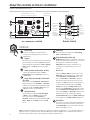
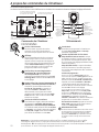
About the controls on the air conditioner.
Features and appearance will vary.
Lights next to the touch pads on the air conditioner control panel indicate the selected settings.
Fan Fan
Delay 1–24hr
Delay timer
Decrease
Mode select
Fan speed
Decrease
Temperature
set Increase
and Decrease
Delay
timer
Increase
Auto Fan
on
Fan speed
Increase
Unit power
on/off
Air Conditioner Controls
Controls
Power Pad
Turns air conditioner on and off. When
turned on, the display will show the room
temperature.
Display
Shows the room temperature or time remaining
on the Delay timer. Shows the Set temperature
while setting the temperature in Cool or Energy
Saver modes. The Set light will turn on while
setting.
Temp Increase Ÿ /Decrease ź Pads
Use to set temperature when in Cool or
Energy Saver mode. The Set light will turn on
while setting.
Delay Timer IncreaseŸ (+) /Decrease
ź(–) Pads
Each touch of the Increase Ÿ / Decrease ź
pads on the unit or the Increase + / Decrease
– pads on the remote control will set the delay
time when using the Delay 1–24hr timer. The
Set light will turn on while setting.
Fan Speed Pads
Use to set the fan speed to Low, Med, High
or Auto on the unit. NOTE: On the remote
control, use the fan speed Increase + /
Decrease – pads to set the fan speeds to Low,
Med or High. Use the Auto pad to turn Auto
fan on.
Mode Pad
Use to set the air conditioner to Cool, Energy
Saver or Fan Only mode.
Delay Pads/Delay 1-24hr Pad
'HOD\21³When the air conditioner is off, it can
be set to automatically come on in 1 to 24 hours
at its previous mode and fan settings.
'HOD\2))³When the air conditioner is on,
it can be set to automatically turn off in 1 to
24 hours.
How to set:
Press the Delay 1–24hr pad on the unit or the
Delay pad on the remote control. Each touch
of the Increase Ÿ / Decreaseźpads on the
unit or the Increase + / Decrease – pads on
the remote control will set the timer in 1-hour
intervals. The Set light will turn on while setting.
To review the remaining time on the Delay
1–24hr timer, press the Delay 1–24hr pad on
the unit or the Delay pad on the remote control.
Use the Increase Ÿ / Decrease ź pads on the
unit or the Increase + / Decrease – pads on the
remote control to set a new time if desired.
To cancel the timer, press the Delay 1–24hr pad
until the light on the Delay 1–24hr pad goes off.
Reset Filter
LED will turn on when fan has accumulated 250
hours of run time as a reminder to clean filter.
Press Reset Filter to turn off the LED and reset
the accumulated run time.
Note: The default temperature reading on the display is degree Fahrenheit ( °F). To change the display to
degree Celcius (°C), press the Temp Increase Ÿ and Temp Decrease ź buttons together and hold for 3
seconds. Repeat the process to change back to degree Fahrenheit (°F)
NOTE: The display always shows the room temperature except
when setting the Set temperature or the Delay timer.
Power
On/Off
Fan Mode
Auto
Reset
Filter
High
Med
Low
Cool
Fan Only
Energy Saver
Delay
1-24 Hrs
Set
+
-
8
Light indicates the
delay timer is set.
Light indicates the unit is in the
temperature or delay time Set mode.
Remote Control

5
GEAppliances.com
Cool Mode
Use the Cool mode at Low, Med, High or Auto Fan
Speed for cooling. Use the Temperature Increase Ÿ
/ Decrease ź pads to set the desired temperature
between 64°F and 86°F in 1°F increments.
An electronic thermostat is used to maintain the room
temperature. The compressor will cycle on
and off to keep the room at the set level of comfort.
Set the thermostat at a lower number and the indoor
air will become cooler. Set the thermostat at a higher
number and the indoor air will become warmer.
NOTE: If the air conditioner is off and is then turned on
while set to a Cool setting or if turned from a fan
setting to a Cool setting, it may take approximately
3 minutes for the compressor to start and cooling to
begin.
Cooling Descriptions
For Normal Cooling³6HOHFWWKHCool mode and
High or Med fan with a middle set temperature.
For Maximum Cooling³6HOHFWWKH Cool mode
and High fan with a lower set temperature.
For Quieter and Nighttime Cooling³6HOHFWWKH
Cool mode and Low fan with a middle set
temperature.
Fan Only Mode
Use the Fan Only Mode at Low, Med or High fan
speed to provide air circulation and filtering without
cooling. Since fan-only settings do not provide
cooling, a Set temperature cannot be entered. The
room temperature will appear in the display.
NOTE: Auto Fan Speed cannot be used when in the
Fan Only Mode.
Energy Saver Mode
In the case of a power outage or interruption, the
unit will automatically restart in the settings last
used after the power is restored. If the Delay 1–24hr
feature was set, it will resume countdown. You may
need to set a new time if desired.
Power Outage Recovery Feature
Set to Auto fan speed for the fan speed to
automatically set to the speed needed to provide
optimum comfort settings with the set temperature.
If the room needs more cooling, the fan speed
will automatically increase. If the room needs less
cooling, the fan speed will automatically decrease.
NOTE: Auto Fan Speed cannot be used when in the
Fan Only Mode.
Auto Fan Speed
Do Not Operate in Freezing Outdoor Conditions
This cool-only air conditioner was not designed for
freezing outdoor conditions. It must not be used in
freezing outdoor conditions.
To ensure proper operation, aim the remote
control at the signal receiver on the air
conditioner.
Make sure nothing is between the air conditioner
and the remote control that could block the
signal.
The remote control signal has a range of
up to 20 feet.
Make sure batteries are fresh and installed
correctly as indicated on the remote control.
Remote contains a magnet allowing it to attach
to metal surfaces.
Remote Control
This mode optimizes the cooling power of your air
conditioner, thereby saving you energy. Once the
set point temperature has been reached, the fan
will cycle off to save energy. The fan will cycle back
on periodically to insure all cooling capacity in the
system is used. This mode is the default mode for the
unit. Each time the unit is powered off, it will restart
in Energy Saver mode ON. This includes Delay timer
mode. The first time the unit is turned on, the settings
will be 70° and Low fan. You can adjust the fan
speed and temperature to your personal comfort.
Energy Saver ON³Helps minimize electricity use.
It is normal for the fan to cycle off and then back
on in this mode. This on/off cycle can repeat
multiple times. Because the fan will cycle off, you
may notice a variation in room temperature and
humidity.
Energy Saver OFF³When this mode is not engaged,
the fan will run continuously, and in Cool mode the
compressor will cycle on and off to maintain room
temperature.

6
Air Direction
Use the lever to adjust the air direction left and right
only.
About the controls on the air conditioner
Additional important information.
Turn the air conditioner off and remove the plug from
the wall outlet before cleaning.
To clean, use water and a mild detergent. Do not use
bleach or abrasives.
Grille and Case
Care and cleaning of the air conditioner.
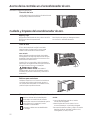
Outdoor Coils
The coils on the outdoor side of the air conditioner
should be checked regularly. If they are clogged with
dirt or soot, they may be professionally cleaned.
1
Remove the battery cover by sliding it according
to the arrow direction.
2
Insert new batteries, making sure that the (+)
and (–) of battery are installed correctly.
3
Reattach the cover by sliding it back
into position.
NOTES:
Use 2 “AAA” (1.5 volt) alkaline batteries. Do not
use rechargeable batteries.
Remove the batteries from the remote control if
the system is not going to be used for a long time.
Do not mix old and new batteries. Do not mix
alkaline, standard (carbon-zinc) or rechargeable
(ni-cad, ni-mh, etc) batteries.
How to Insert the Batteries in the Remote Control
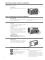
Air Filter
The air filter behind the front grille should be checked
and cleaned at least every 30 days or
more often if necessary.
To remove:
Open the inlet grille by pulling downward on the tabs
at the top upper corners of the inlet grille until the
grille is in a 45º position. Remove the filter.
Clean the filter with warm, soapy water. Rinse and let
the filter dry before replacing it. Do not clean the filter
in a dishwasher.
CAUTION: DO NOT operate the air
conditioner without a filter because dirt and lint will
clog it and reduce performance.
Tab Tab

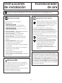
BEFORE YOU BEGIN
Read these instructions completely
and carefully.
•
IMPORTANT ³ Save these instructions
for local inspector’s use.
•
IMPORTANT ³ Observe all governing
codes and ordinances.
•
Note to Installer – Be sure to leave these
instructions with the Consumer.
• Note to Consumer – Keep these instructions for
future reference.
• Skill level – Installation of this appliance requires
basic mechanical skills.
• Completion time –
Approximately 1 hour
• We recommend that two people install
this product.
• Proper installation is the responsibility
of the installer.
• Product failure due to improper installation is not
covered under the Warranty.
• You MUST use all supplied parts and use proper
installation procedures as described in these
instructions when installing this air conditioner.
Installation
Air Conditioner
Instructions
Some models require a 115/120-volt AC,
60-Hz grounded outlet protected with a
15-amp time-delay fuse or circuit breaker.
The 3-prong grounding plug minimizes the
possibility of electric shock hazard. If the wall outlet
you plan to use is only a 2-prong outlet, it is your
responsibility to have it replaced with a properly
grounded 3-prong wall outlet.
Some models require 230/208-volt AC,
protected with a time-delay fuse or circuit
breaker. These models should be installed on
their own single branch circuit for best
performance and to prevent overloading
house or apartment wiring circuits, which
could cause a possible fire hazard from
overheating wires.
ELECTRICAL REQUIREMENTS
CAUTION:
Do not, under any circumstances, cut or remove
the third (ground) prong from the power cord.
Do not change the plug on the power cord
of this air conditioner.
Aluminum house wiring may present special
SUREOHPV³FRQVXOWDTXDOLILHGHOHFWULFLDQ
7
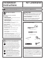
TOOLS YOU WILL NEED
Phillips head screwdriver
Ruler or tape measurePencil
Level
Scissors or knife
Flat-blade screwdriver
Power cord includes a current interrupter device. A
test and reset button is provided on the plug case. The
device should be tested on a periodic basis by first
pressing the TEST button and then the RESET button
while plugged into the outlet. If the TEST button does
not trip or if the RESET button will not stay engaged,
discontinue use of the air conditioner and contact a
qualified service technician.
Questions? Call 800.GE.CARES (800.432.2737) or Visit our Website at: GEAppliances.com

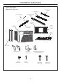
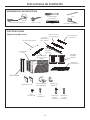
Window/accordion frame
locking bracket (1)
Sill angle
bracket (2)
Right
accordion
panel
Left
accordion
panel
Type A
screws (10)
Type C
screws (5)
Type E bolt
with nut (4)
V-supports (2)
Type F bolt
with nut (2)
Side rail (2)
8
Installation Instructions
PARTS INCLUDED
(Appearance may vary)
Top mounting rail
Air
conditioner
Top mounting rail
seal strip
Foam
Insulation (2)
Foam top window
gasket
Window
sill and sash seal (2)
Accordion panel
seal (2)

STORM WINDOW REQUIREMENTS
A storm window frame will not allow the air
conditioner to tilt toward the outside, and will keep it
from draining properly.
To adjust for this, attach a piece of wood to the sill.
WOOD PIECES
WIDTH: 2”
LENGTH: Long enough to fit inside the window
frame.
THICKNESS: To determine the thickness, place a
piece of wood on the sill to make it 1/2s higher
than the top of the storm window frame or the vinyl
frame.
Attach securely with nails or screws provided by the
installer.
Installation Instructions
WINDOW REQUIREMENTS
• These instructions are for a standard double-hung
window. You will need to modify them for other types
of windows.
• All supporting parts must be secured
to firm wood, masonry or metal.
• The electrical outlet must be within reach of the
power cord.
• Follow the dimensions in the table and illustration
for your model.
1
19 1/4”
(With accordion panels)
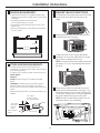
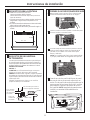
PREPARE THE AIR CONDITIONER
Pull down the front panel and remove the filter.
Remove the front panel by lifting up at an
angle.
Remove the four front screws. Save them for
reinstalling the front housing.
Grasp the lower corners of the grille while
pressing in on the case sides with your finger
tips. Pull out to release and lift it up.
NOTE: Do not pull the bottom edge toward you
more than 3s or you may damage the tabs of
the grille.
When the front grille is removed the control
panel will still be attached by a harness. Turn
the grille around so you can see the back side
of the grille. Remove the 2 screws to separate
the control panel housing from the grille.
NOTE: Be sure to save these screws. You will
need them later in the installation.
3
A
B
30”- 41”
2
1/2shigher
than storm
window
frame
Storm window
frame
Wood
Sill
1/2shigher
than vinyl frame
(on some windows)
Vinyl frame
9
C
D
Remove Screws

Installation Instructions
10
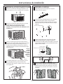
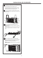
PREPARE THE AIR CONDITIONER
(continues)
Remove the shipping screws located on the top
of the case.
Remove the ground screws from each side of
the case. Keep them in a safe location.
NOTE: Be sure to save these screws. You will
need them later in the installation.
Slide the air conditioner from the case by
gripping the base pan handle and pulling
forward while bracing the case. Do not pull or
lift on the foam discharge area.
Your unit may come with internal packaging.
This packaging must be removed prior to
installing the air conditioner back into the
cabinet.
3
E
F
FRONT
Do not
pull or
lift in this
DUHD³
damage
to the
unit may
result
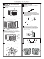
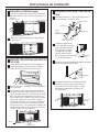
PREPARE THE CASE
Attach the top rail gasket to the bottom of
the top rail.
Install the top mounting rail with 4 type A
screws from the inside of the case. Press firmly
to drive the screws into the gasket and through
the top mounting rail.
Slide each side retainer onto the edge of
each according panel. The figure shows the
orientation of each accordion panel and side
retainer assembly relative to the case from a
top view of the unit.
Remove the backing from the accordion
seal (two short strips). Stick one sealing strip
respectively on the left side and right side of
the accordion panels, as shown.
A
Top mounting rail
B
4
G
H
C
D
WINDOW FILLER PANEL
WINDOW FILLER PANEL
SIDE RETAINER
SIDE RETAINER

Installation Instructions
11
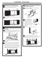
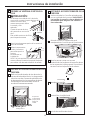
PREPARE THE WINDOW AND INSTALL
THE CASE
Cut the window seal (2 long strips) to the proper
length. Peel off the backing and attach the seal to
the underside of the window sash.
Open the window and mark the center of the
window sill.
Carefully slide the case into the window and
center the case. Lower the window behind
the top mounting rail. Pull the bottom of the
case forward so that the bottom mounting rail
is tight against the back of the window stool.
Mount the case to the window sill using 2 type
C screws. Drill pilot holes, if necessary.
5
PREPARE THE WINDOW AND INSTALL
THE CASE (continues)
Assemble the V-support and V-support bracket
with Type F nut and bolt
Position the V-supports
on the case bottom so
that they will be near the
outside wall. Attach a
V-support to each side of
the bottom of the case with
Type E bolts, 2 for each
support.
Adjust sill angle brackets to rest on sill.
Extend the left and right accordion panels
to the vertical window sashes. Drill pilot holes and
attach the top corners with 2 type C screws.
5
2 type C screws
Stool
B
A
C
D
V-support
F
Sill
Bracket
G
E
Left
Sill angle
bracket
V-support Type
F bolt and nut
Right
Type E bolt
and nut
PREPARE THE CASE (continues)
Slide the left and right accordion panels into
the top and bottom mounting rails.
Attach the side retainers to the case using 6 type
A screws.
4
E
Type C
screw
Type C
screw
Top left
Top right
Bottom mounting rail
F
Sealing Strip
(with adhesive)

12
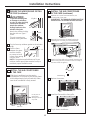
5
PREPARE THE WINDOW AND INSTALL
THE CASE (continues)
Cut the foam top window gasket to the window
width.
Stuff the foam
between the glass
and the window
to prevent air and
insects from getting
into the room.
NOTE: If the gasket supplied does not fit your
window, obtain appropriate material locally to
provide a proper installation seal.
H
CAUTION:
To prevent broken glass
or damage to windows,
on vinyl or other similarly
constructed windows,
attach the window
locking bracket to the
window side jamb.
Attach the window locking
bracket with one Type C
screw.
This unit contains two
window locking brackets.
I
J
Wood
Vinyl
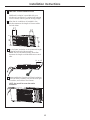
INSTALL THE AIR CONDITIONER
IN THE CASE (continues)
Replace the 1 screw removed earlier, one
on each side of the case.
IMPORTANT: THE GROUND SCREWS MUST BE
REINSTALLED TO ENSURE PROPER GROUND.
Reinstall the control to the panel housing by
replacing the 2 screws you removed earlier.
Attach the front grille to the case by inserting the
tabs on the grille into the slots on the front top of
the case. Push the grille in.
Replace the screws.
Install the filter and the front grille.
Plug in the air conditioner.
6
B
C
INSTALL THE AIR CONDITIONER
IN THE CASE
Slide the air conditioner into the case by
the base pan. Do not push on the controls, foam
air discharge housing or the finned coils. Make
sure the air conditioner is firmly seated.
6
A
Do not press on
WKHVHDUHDV³
damage to the unit
may result
Base Pan
D
E
F
Installation Instructions
G
Remove Screws
Install Screws

Installation Instructions
13
INSTALL FOAM INSULATION
Additional insulation is provided with your
window air conditioner to reduce heat leakage
into the home, reducing overall energy usage.
After the air conditioner is installed in the
window measure the length of the accordion
for both sides.
Cut the foam insulation to the measured length
of the left and right side accordion.
NOTE: Be sure to measure each accordion
because the length could be different on each
side.
Remove adhesive from back of foam insulation.
Stick the foam insulation onto the left and right
accordion, and inside of the frames.
NOTE: be careful to cover the entire
accordion.
7
A
/
+
/
+
/RU/
B
C

14
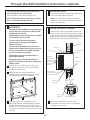
7KURXJKWKH:DOO,QVWDOODWLRQ,QVWUXFWLRQV³2SWLRQDO
The case may be installed through-the-wall in
both existing and new construction.
Read completely, then follow step-by-step.
NOTE: Obtain all materials locally for mounting
the air conditioner through-the-wall.
IMPORTANT
Through-the-wall installation is not appropriate
if any of the side or top louvers in the case will
be obstructed by the wall.
All side and top louvers in the case must project
on the outdoor side of the wall.
The room side of the case must project
into the room far enough to maximize the
balance of the unit.
The case must be installed level from side-to-
side and with a slight tilt from front to rear. Use
a level; no more than a 1/2 bubble will be the
correct case slant to the outside.
/LQWHODQJOHLVUHTXLUHGWRVXSSRUWEULFNVRU
blocks above opening.
)ODVKLQJLVUHTXLUHGDQGVKRXOGH[WHQGWKH
length of the opening to ensure no inside cavity
leakage occurs.
Remove the air conditioner from the case.
For specific instruction, refer to the Window
Installation Instructions.
Make certain that a wall receptacle is
available close to the hole location or make
arrangements to install a receptacle.
Place the case in the wall opening and
place wood support strips between the case
bottom and the flashing on both sides of the
bottom rail. They should be the same height as
the bottom rail and the same length as the wall
opening.
1
A
B
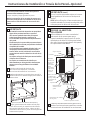
FINISH THE WALL OPENING
Caulk all four sides on the outdoor side of the
case to prevent moisture from getting through
to the interior wall. Use of flashing (drip rail) will
further prevent water from dripping inside the
wall and down the outside of the building.
Place the air conditioner into the case.
For specific instruction, refer to the Window
Installation Instructions.
2
IMPORTANT (cont.)
Secure with 14 wood screws anchored at least an
inch into the wall support structure.
NOTE: Drill pilot holes, if necessary, for proper
installation. If the frame is oversized, use shims to
prevent case distortion.
1
D
A
B
Lintel angle
Plaster line
Trim molding (if
desired)
INSIDE
Bottom rail
Wood filler and
caulking (above and
below the flashing)
Air louvers (top
and sides must
project on the
outdoor side of
the wall)
OUTSIDE
Flashing
(Drip rail)
Case
bottom
Bottom
rail
Flashing
(Drip rail)
Wood support strips
Caulking
C

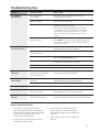
Troubleshooting Tips.
Normal Operating Sounds
You may hear a pinging noise caused by
water being picked up and thrown against the
condenser on rainy days or when the humidity
is high. This design feature helps remove
moisture and improve efficiency.
You may hear the thermostat click when the
compressor cycles on and off.
Water will collect in the base pan during
high humidity or on rainy days. The water
may overflow and drip from the outdoor side
of the unit.
The fan may run even when the compressor
does not.
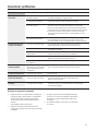
Problem Possible Causes What To Do
Air conditioner The air conditioner • Make sure the air conditioner plug is pushed
does not start is unplugged. completely into the outlet.
The fuse is blown/circuit • Check the house fuse/circuit breaker box and replace
breaker is tripped. the fuse or reset the breaker.
Power failure. •The unit will automatically restart in the settings last
used after the power is restored.
•There is a protective time delay (approximately
3 minutes) to prevent tripping of the compressor
overload. For this reason, the unit may not start
normal cooling for 3 minutes after it is turned
back on.
The current interrupter •Press the RESET button located on the power cord plug.
device is tripped.
•If the RESET button will not stay engaged, discontinue
use of the air conditioner and contact a qualified
service technician.
Air conditioner does Airflow is restricted. • Make sure there are no curtains, blinds or furniture
not cool as it should blocking the front of the air conditioner.
The temp control may • In the Cool mode, press the Decrease dpad.
not be set correctly.
The air filter is dirty. • Clean the filter at least every 30 days.
See the Care and Cleaning section.
The room may have been hot. • When the air conditioner is first turned on, you need
to allow time for the room to cool down.
Cold air is escaping. • Check for open furnace registers and cold air returns.
Cooling coils have iced up. •See “Air conditioner freezing up” below.
Air conditioner Ice blocks the air flow • Set the controls at High Fan or High Cool and set the
freezing up and stops the air conditioner thermostat to a higher temperature.
from cooling the room.
The remote control The batteries are inserted • Check the position of the batteries. They should be
is not working incorrectly. inserted in the opposite (+) and (–) direction.
The batteries may be dead. • Replace the batteries.
Water drips outside Hot, humid weather. • This is normal.
Water drips indoors The air conditioner is not • For proper water disposal, make sure the air conditioner
tilted to the outside. slants slightly from the case front to the rear.
Water collects in Moisture removed from air • This is normal for a short period in areas with little
base pan and drains into base pan. humidity; normal for a longer period in very humid areas.
15

Staple your receipt here.
Proof of the original purchase
date is needed to obtain service
under the warranty.
*($LU&RQGLWLRQHU³2QH<HDU/LPLWHG:DUUDQW\
For The Period Of: GE Will Replace:
One Year Any part of the air conditioner which fails due to a defect in materials or workmanship.
From the date of the During this limited one-year warranty, GE will also provide, free of charge, all labor and related
original purchase service to replace the defective part.
All warranty service provided by our Factory Service Centers,
or an authorized Customer Care
®
technician. To schedule service,
visit us on-line at ge.com, or call 800.GE.CARES (800.432.2737).
Have serial number and model number available when calling
for service.
Service trips to your home to teach you how to
use the product.
Improper installation, delivery or maintenance. If you
have an installation problem, or if the air conditioner
is of improper cooling capacity for the intended use,
contact your dealer or installer. You are responsible
IRUSURYLGLQJDGHTXDWHHOHFWULFDOFRQQHFWLQJIDFLOLWLHV
Failure of the product resulting from modifications to
the product or due to unreasonable use including failure
to provide reasonable and necessary maintenance.
In commercial locations, labor necessary to move the
unit to a location where it is accessible for service
by an individual technician.
Replacement of house fuses or resetting of circuit
breakers.
Failure due to corrosion on models not corrosion-
protected.
Damage to the product caused by improper power
supply voltage, accident, fire, floods or acts of God.
,QFLGHQWDORUFRQVHTXHQWLDOGDPDJHFDXVHGE\SRVVLEOH
defects with this air conditioner.
Damage caused after delivery.
What Is Not Covered:
This warranty is extended to the original purchaser and any succeeding owner for products purchased for
home use within the USA. If the product is located in an area where service by a GE Authorized Servicer is
not available, you may be responsible for a trip charge or you may be required to bring the product to an
Authorized GE Service location for service. In Alaska, the warranty excludes the cost of shipping or service calls
to your home.
Some states do not allow the exclusion or limitation of incidental or consequential damages. This warranty
gives you specific legal rights, and you may also have other rights which vary from state to state. To know
what your legal rights are, consult your local or state consumer affairs office or your state’s Attorney General.
Warrantor: General Electric Company. Louisville, KY 40225
(;&/86,212),03/,(':$55$17,(6³<RXUVROHDQGH[FOXVLYHUHPHG\LVSURGXFWUHSDLUDVSURYLGHGLQ
this Limited Warranty. Any implied warranties, including the implied warranties of merchantability or
fitness for a particular purpose, are limited to one year or the shortest period allowed by law.
16

17
Instrucciones de seguridad .........18, 19
Instrucciones de operación
Controle ..................................20-22
Cuidado y limpieza
Bobinas para exteriores ......................22
Filtro de aire ..................................22
Instrucciones de instalación .......23-30
Solucionar problemas ...................31
Sonidos de operación normales ..............31
Servicio al consumidor
Garantía ......................................34
Servicio al consumidor .......................35
Escriba los números de modelo
y serie aquí:
# de Modelo _________________
# de Serie ___________________
Puede encontrar estos números
en una etiqueta en el costado
del acondicionador de aire.
AEL24

18
INFORMACIÓN IMPORTANTE DE SEGURIDAD.
LEA TODAS LAS INSTRUCCIONES ANTES DE USAR.
Por su seguridad, se debe seguir la información en este manual para minimizar el riesgo de incendios, descargas
eléctricas o lesiones personales.
Use este electrodoméstico solamente para el
propósito determinado según se describe en el
Manual del propietario.
Este acondicionador de aire debe instalarse
correctamente de acuerdo con las Instrucciones de
instalación antes de su uso.
Nunca desenchufe su acondicionador de aire tirando
del cable eléctrico. Siempre agarre firmemente el
enchufe y tire de él directamente hacia afuera.
Reemplace inmediatamente todos los cables
eléctricos que se hayan pelado o que se hayan
dañado de alguna otra manera. Un cable de
corriente dañado no debe repararse, sino que debe
ser sustituido por uno nuevo que se adquiera del
fabricante. No use un cable eléctrico que muestre
evidencias de deterioro, o daños de abrasión en su
superficie en alguno de sus extremos.
Apague la unidad y desenchufe su acondicionador de
aire antes de limpiar.
GE no está no apoya que se le proporcione ningún
servicio al acondicionador de aire. Vehementemente
recomendamos que usted no intente proporcionar
servicio al acondicionador de aire usted mismo.
Por su seguridad…no almacene ni use materiales
combustibles, gasolina u otros vapores o líquidos
inflamables en la proximidad de éste o algún otro
electrodoméstico.
Todos los acondicionadores de aire contiene
refrigerantes, los que por Ley Federal deben ser
removidos antes de desecharlos. Si usted planea
deshacerse de algún producto que contenga
refrigerantes, póngase en contacto con la compañía
que
se encarga de recoger su basura para que le
indiquen qué hacer.
Si el receptáculo no coincide con el enchufe, un
electricista calificado debe reemplazar el receptáculo.
Estos sistemas de acondicionadores de aire R410A
requieren que los contratistas y técnicos usen
herramientas, equipos y estándares de seguridad
aprobados para su uso con este refrigerante. NO use
equipamiento certificado sólo para refrigerante R22.
PRECAUCIONES DE SEGURIDAD
ADVERTENCIA
INFORMACIÓN DE SEGURIDAD
Éste es el símbolo de alerta de seguridad. El mismo alerta sobre potenciales riesgos de muerte o lesiones tanto para usted
con para otras personas. Todos los mensajes de seguridad estarán a continuación del símbolo de alerta de seguridad y con la
palabra “PELIGRO”, “ADVERTENCIA” o “PRECAUCIÓN”. Estas palabras se definen como:
PELIGRO
Signale une situation qui présente un danger imminent et qui, si elle n’est pas évitée, entraînera des blessures
graves, voire la mort.
ADVERTENCIA
Signale une situation qui présente un danger imminent et qui, si elle n’est pas évitée, peut entraîner des
blessures graves, voire la mort. .
PRECAUCIÓN
Signale une situation qui présente un danger imminent et qui, si elle n’est pas évitée, peut entraîner des
blessures mineures ou graves.

19
LEA Y SIGA ESTAS INSTRUCCIONES DE SEGURIDAD
CUIDADOSAMENTE.
Bajo ninguna circunstancia, corte o remueva la tercera
púa (tierra) del cable eléctrico. En pos de la seguridad
personal, este electrodoméstico debe siempre conectarse
a tierra.
NO use un enchufe adaptador con este
electrodoméstico.
El cable eléctrico de este electrodoméstico está
equipado con un enchufe de tres púas (tierra) que
combina con un tomacorriente estándar de tres tomas
de pared para minimizar la posibilidad de una descarga
eléctrica.
El cable de alimentación incluye un dispositivo para
interrupción de corriente. Se incluye un botón de prueba
y de reinicio en el dispositivo. El dispositivo debe ponerse
a prueba periódicamente: primero se presiona el botón
de TEST (prueba) y luego RESET (reinicio) mientras se
encuentra enchufado al tomacorriente. Si el botón
TEST no se dispara o si el botón RESET no queda
enganchado, deje de utilizar el acondicionador de aire y
comuníquese con un técnico calificado.
Pida a un técnico que inspeccione el tomacorriente y el
circuito para cerciorarse de que el tomacorriente está
conectado a tierra de la manera apropiada.
Donde exista un tomacorriente de dos tomas, es su
responsabilidad y obligación personal hacer que dicho
tomacorriente sea reemplazado por uno de tres tomas
con conexión a tierra.
El acondicionador de aire debería siempre estar
conectado a un tomacorriente individual con su circuito
de voltaje correspondiente.
Esto proporciona el mayor rendimiento y además evita
que los circuitos del resto de la casa se sobrecarguen, lo
cual podría causar incendios por el sobrecalentamiento
del cableado.
Ver las Instrucciones de instalación, en la sección
Requisitos Eléctricos para los requisitos específicos de
conexión.
CÓMO CONECTAR LA ELECTRICIDAD
USO DE PROLONGADORES
GUARDE ESTAS INSTRUCCIONES
RIESGO DE INCENDIO. Podría ocasionar lesiones
graves o la muerte.
• NO use un prolongador con este Acondicionador de
Aire de Ventana.
• NO use protectores contra picos de tensión ni
adaptadores para múltiples tomacorrientes con este
Acondicionador de Aire de Ventana.
INFORMACIÓN SOBRE RECICLAJE
Para acceder a información sobre reciclaje de
electrodomésticos, visite www.geappliances.com/
recycling.
ADVERTENCIA

20
A propos des commandes du climatiseur.
Commandes
Touche d’alimentation
Met le climatiseur en position de marche
ou d’arrêt. L’écran affiche la température
de la pièce lorsque l’appareil est mis en marche.
Affichage
Affiche la température de la pièce ou le temps
restant avant la mise en marche ou l’arrêt de
l’appareil. Affiche la température de réglage lors
de la programmation de la température pour les
modes Cool (refroidissement) ou Energy Saver
(economie d’energie). Le témoin lumineux Set
(programmé) s’allume lors du réglage.
Touches Temp Increase (Augmentation
température) Ÿ / Decrease (Réduction
de la température)ź
Sont utilisées pour
programmer la température dans les modes Cool
ou Energy Saver. Le témoin lumineux Set s’allume
lors du réglage.
Touches Delay Timer Increase (Augmentation du
délai)Ÿ (+) / Decrease (Diminution du délai) ź(-)
Chaque fois que vous effleurez les touches
Increase Ÿ / Decreaseź sur l’appareil ou
les touches Increase + / Decrease – de la
télécommande, vous programmez la durée
du délai lors de l’utilisation de la minuterie Delay
1-24hr (délai de 1-24h). Le témoin lumineux Set
s’allume lors du glage.
Touches de vitesse du ventilateur
Sont utilisées pour régler la vitesse du ventilateur
de l’appareil sur Low (faible), Med (moyenne),
High (elevée) ou Auto (automatique). REMARQUE :
Sur la télécommande, utilisez les touches Increase
+ / Decrease – pour régler la vitesse du ventilateur
sur Low, Med, ou High. Utilisez la touche Auto
pour allumer le ventilateur en mode Auto.
Touche Mode
Est utilisée pour programmer le climatiseur sur
les modes Cool , Energy Saver ou Fan Only
(ventilateur uniquement).
Touches de Délai/
Délai de 1 à 24 heures
Delay ON (délai de mise en marche)³/RUVTXH
le climatiseur est éteint, il peut être programmé
pour démarrer automatiquement dans un délai
de 1 à 24 heures à ses réglages précédents (mode,
vitesse du ventilateur).
Delay OFF (délai d’arrêt³/RUVTXHOHFOLPDWLVHXU
est en fonctionnement, il peut être programmé
pour s’arrêter automatiquement dans un délai de
1 à 24 heures.
Comment le programmer :
Appuyez sur la touche Delay 1-24hr (Délai de 1
à 24 heures) de l’appareil ou
Delay pad (Touches de
Délai)
de la télécommande. Chaque fois que vous
effleurez les touches Increase Ÿ / Decrease źsur
l’appareil ou les touches Increase + / Decrease
– de la télécommande, vous programmez la
durée du délai par intervalle de 1 heure. Le témoin
lumineux Set s’allume lors du réglage.
Pour connaître le temps restant sur la minuterie
Delay 1-24hr, appuyez sur la touche Delay 1-24hr
de l’appareil ou
Delay pad (Touches de Délai)
de
la télécommande.
Utilisez les touches IncreaseŸ
/ Decreaseź sur l’appareil ou les touches
Increase + / Decrease – de la télécommande pour
programmer un nouveau délai si nécessaire.
Pour annuler la minuterie, appuyez sur la touche
Delay 1-24hr jusqu’à ce que le voyant lumineux
sur la touche Delay 1-24hr s’éteigne.
Réinitialisation du Filtre
Le témoin lumineux s’allumera au bout d’un cumul
de 250 heures de fonctionnement du ventilateur
pour rappeler la nécessité de nettoyer le filtre.
Appuyez sur Reset Filter pour éteindre le témoin
et remettre à zéro le temps de fonctionnement
cumulé.
Remarque : La lecture de température par défaut s’affiche en degré Fahrenheit (°F). Pour modifier
l’affichage en degré Celcius (°C), appuyez simultanément sur les boutons d’augmentation
Ÿ
ou
d’abaissement
ź
de la température et maintenez-les enfoncés pendant 3 secondes. Répétez la méthode
pour effectuer un retour à l’affichage des degrés Fahrenheit (°F).
Les fonctions et l’aspect peuvent varier.
Les témoins lumineux à côté des touches à effleurement sur le tableau de commandes du climatiseur indiquent les réglages sélectionnés.
Fan Fan
Délai 1–24hr
Réduction du délai
Sélection du mode
Réduction de
la vitesse du
ventilateur
Augmentation
et Réduction de
la température
programmée
Augmentation
du délai
Marche
automatique du
ventilateur
Augmentation de la
vitesse du ventilateur
Mise en marche
de l’appareil ON/OFF
(marche/arrêt)
NOTE : L’écran affiche toujours la température de la pièce sauf lorsque vous programmez
la température ou la minuterie.
Power
On/Off
Fan Mode
Auto
Reset
Filter
High
Med
Low
Cool
Fan Only
Energy Saver
Delay
1-24 Hrs
Set
+
-
8
Le témoin indique que l’appareil
est en mode Programmation de
la température ou du délai.
Le témoin lumineux indique que
la minuterie est programmée.
Commandes du Climatiseur
Télécommande
La page est en cours de chargement...
La page est en cours de chargement...
La page est en cours de chargement...
La page est en cours de chargement...
La page est en cours de chargement...
La page est en cours de chargement...
La page est en cours de chargement...
La page est en cours de chargement...
La page est en cours de chargement...
La page est en cours de chargement...
La page est en cours de chargement...
La page est en cours de chargement...
La page est en cours de chargement...
La page est en cours de chargement...
La page est en cours de chargement...
La page est en cours de chargement...
-
 1
1
-
 2
2
-
 3
3
-
 4
4
-
 5
5
-
 6
6
-
 7
7
-
 8
8
-
 9
9
-
 10
10
-
 11
11
-
 12
12
-
 13
13
-
 14
14
-
 15
15
-
 16
16
-
 17
17
-
 18
18
-
 19
19
-
 20
20
-
 21
21
-
 22
22
-
 23
23
-
 24
24
-
 25
25
-
 26
26
-
 27
27
-
 28
28
-
 29
29
-
 30
30
-
 31
31
-
 32
32
-
 33
33
-
 34
34
-
 35
35
-
 36
36


