
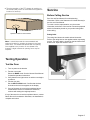
Electric and Induction Ranges
Installation Instructions
Slide-In Ranges
HEI8056C, HEI8056U, HEIP056C, HEIP056U, HIIP056C,
HIIP056U, HII8056C, HII8056U, HII8046C, HII8046U,
HEI8046C, HEI8046U


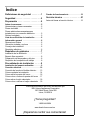
Table of Contents
Questions?
1-800-944-2904
www.bosch-home.com/us
We look forward to hearing from you!
This Bosch Appliance is made by
BSH Home Appliances Corporation
1901 Main Street, Suite 600
Irvine, CA 92614
Safety Definitions . . . . . . . . . . . . . . . 1
Safety . . . . . . . . . . . . . . . . . . . . . . . . . 1
Preparation . . . . . . . . . . . . . . . . . . . . 3
Before You Begin . . . . . . . . . . . . . . . . . . . . . 3
Tools and Parts Needed . . . . . . . . . . . . . . . . 3
Parts Included . . . . . . . . . . . . . . . . . . . . . . . . 3
Additional Parts Needed for Hard-Wired
Installations . . . . . . . . . . . . . . . . . . . . . . . . . . 3
Remove Packaging . . . . . . . . . . . . . . . . . . . . 3
Installation Checklist . . . . . . . . . . . . . . . . . . 3
General Information . . . . . . . . . . . . . . . . . . . 4
Overall Dimensions . . . . . . . . . . . . . . . . . . . . 4
Location Level and Plumb . . . . . . . . . . . . . . . 4
Installation Hints . . . . . . . . . . . . . . . . . . . . . . 4
Electrical Requirements . . . . . . . . . . . . . . . . . 4
Cabinet Requirements . . . . . . . . . . . 5
Install Ventilation . . . . . . . . . . . . . . . . . . . . . . 5
Required Clearance . . . . . . . . . . . . . . . . . . . . 5
Prepare Walls and Floor . . . . . . . . . . . . . . . . 6
Countertop Requirements . . . . . . . . . . . . . . . 6
Installation Procedure . . . . . . . . . . . 7
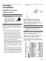
Installation of the Anti-Tip Bracket . . . . . . 7
Electrical Connection . . . . . . . . . . . . . . . . . 7
Connect Flexible Conduit . . . . . . . . . . . . . . . 10
Complete the installation . . . . . . . . . . . . . . . 11
Removing the Oven Door . . . . . . . . . . . . . . 13
Replacing the Oven Door . . . . . . . . . . . . . . 14
Removing the Warming Drawer . . . . . . . . . . 15
Replacing the Warming Drawer . . . . . . . . . . 15
Testing Operation . . . . . . . . . . . . . . . . . . . 17
Service . . . . . . . . . . . . . . . . . . . . . . . 17
Before Calling Service . . .
. . . . . . . . . . . . . . 17


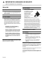
9 IMPORTANT SAFETY INSTRUCTIONS
READ AND SAVE THESE INSTRUCTIONS
English 1
Safety Definitions
NOTICE: This indicates that damage to the appliance or
property may occur as a result of non-compliance with this
advisory.
Note: This alerts you to important information and/or tips.
Safety
PLEASE READ ALL INSTRUCTIONS BEFORE USING
THIS APPLIANCE.
Appliance Handling Safety
Do not lift appliance by the oven door handle. Remove the
oven door for easier handling and installation. See the
section “Removing the Oven Door” in the range Use and
Care manual.
Disposing of Packaging Materials
Remove all tape and packaging before using the range.
Properly dispose of the carton and plastic bags after
unpacking the range. Never allow children to play with
packaging materials.
9 WARNING
This indicates that death or serious injuries may
occur as a result of non-observance of this warning.
9 CAUTION
This indicates that minor or moderate injuries may
occur as a result of non-observance of this warning.
9 WARNING
If the information in this manual is not followed
exactly, fire or shock may result causing property
damage or personal injury.
9 WARNING
Do not repair or replace any part of the appliance
unless spe
cifically recommended in the manuals.
Improper installation, service or maintenance can
cause injury or property damage. Refer to this
manual for guidance. All other servicing should
be done by an authorized servicer.
• Ask your dealer to recommend a qualified
technician and an authorized repair service.
• Install only per the installation instructions
provided in the literature package
accompanying this range.
• Never modify or alter the construction of the
range including by removing leveling legs,
panels, wire covers, anti-tip brackets or
screws, or any other part of the appliance.
9 WARNING
TIP OVER HAZARD!
A child or adult can tip the
range over and be killed.
Verify that the anti-tip
bracket is securely installed.
Ensure the anti-tip bracket
is engaged whenever the
range is moved to a new
location.
Do not operate the range without the anti-tip bracket
in place. Failure to follow the instructions in this
manual can result in death or serious burns to
children and adults.
Check for proper installation and use of the anti-tip
bracket. Carefully tip the range forward pulling from
the back to ensure that the anti-tip bracket engages
the range leg and prevents tip-over. Range should
not move more than 1” (2.5 cm).
9 CAUTION
• Unit is heavy and requires at least two persons
or proper equipment to move.
• Hidden surfaces may have sharp edges. Use
caution when reaching behind or under
appliance.
• Do not use the oven or warming drawer (if
equipped) for storage.

9 IMPORTANT SAFETY INSTRUCTIONS
READ AND SAVE THESE INSTRUCTIONS
English 2
Safety Codes and Standards
This appliance complies with one or more of the following
Standards:
• UL 858, Household Electric Ranges
• CAN/CSA-C22.2 No. 61 Household Cooking Ranges
It is the responsibility of the owner and the installer to
determine if additional requirements and/or standards
apply to specific installations.
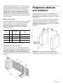
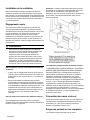
Installation Location
To eliminate the risk of burns or fire by reaching over
heated surface units, cabinet storage space located above
the surface units should be avoided. If cabinet storage is to
be provided, the risk can be reduced by installing a hood
that projects horizontally a minimum of 5" (12.7 cm) beyond
the bottom of the cabinet.
Verify that cabinets above the range are a maximum of 13"
(330 mm) deep.
Child Safety
Do not store items of interest to children in the cabinets
above the range or on the backguard of a range. Children
climbing on the range to reach items could be seriously
injured.
Electric Safety
Before you plug in an electrical cord, be sure all controls
are in the OFF position.
Be sure your appliance is properly installed and grounded
by a qualified technician in accordance with the National
Electrical Code ANSI/NFPA 70 latest edition and local
electrical code requirements.
Local codes vary. Installation, electrical connections and
grounding must comply with all applicable codes.
For appliances equipped with a cord and plug, do not cut or
remove the ground prong. It must be plugged into a
matching grounding type receptacle to avoid electrical
shock. If there is any doubt as to whether the wall
receptacle is properly grounded, the customer should have
it checked by a qualified electrician.
If required by the National Electrical Code (or Canadian
Electrical Code), this appliance must be installed on a
separate branch circuit.
Only a power supply cord kit rated for this appliance and
marked “for use with ranges” shall be used.
Installer - show the owner the location of the circuit
breaker or fuse. Mark it for easy reference.
Important - Save these instructions for the local electrical
inspector's use.
Before installing, turn power OFF at the service panel. Lock
service panel to prevent power from being turned ON
accidentally.
Refer to rating label for more information.
See "Rating Label" under "Service" for rating label
location.
.
Proposition 65 Warning:
This product may contain a chemical known to the State
of California, which can cause cancer or reproductive
harm. Therefore, the packaging of your product may bear
the following label as required by California:
STATE OF CALIFORNIA PROPOSITION 65 WARNING:
WARNING
&DQFHUDQG5HSURGXFWLYH+DUPwww.P65Warnings.ca.gov

English 3
Preparation
Before You Begin
Tools and Parts Needed
• 40 or 50 Amp power supply cord kit with strain relief
(depending on local code).
Note: Not necessary for Canadian installations, cord is
preinstalled at factory.
• Measuring Tape
• Phillips Head Screwdriver
•1¼" Wrench
• Pencil
• T-20 Torx Screwdriver
• Screws (2) and Anchors (2) for Anti-Tip Bracket (Style
will vary depending on mounting surface)
• Level
• Drill and Drill Bit (3/16" masonry bit for concrete
screws)
• Soapy Water
• Safety Gloves and Goggles
• Cloth or Cardboard (Optional - to Protect Floor)
Parts Included
• Anti-Tip Bracket
• 2 wood screws
• 2 anchorless concrete screws
• Foam Tape (unless already installed on underside of
cooktop sides)
• Terminal lugs (for use with hard-wired installations)
Note: Terminal lugs are not necessary for Canadian
installations.
Additional Parts Needed for Hard-Wired
Installations
• Flexible conduit
• Torque wrench
Note: Power supply cord kit is not necessary for hard-wired
installations.
cabinet dimensions are correct for your unit and
that the r
equired electrical connections are
present.
___ 2. Refer to the installation manual for content
regarding Safety, Cabinet Dimensions, Removing
Packaging, Electrical Installation, Testing the
Installation and Customer Service.
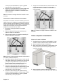
Remove Packaging
1.
Cut the straps.
2.
3.
Open top of carton and remove top wood frame.
Lift the carton up and over the appliance to remove, or
carefully cut along the cut line on the back left side of
the carton with a blade shorter than 3/4” and remove
carton.
4.
Carefully remove internal protective packaging taking
care to secure any loose accessories and instruction
manuals.
5.
Remove bracket(s) securing appliance to base pad, if
present.
6.
The unit should stay on the packaging base until ready
to be lifted into cabinet cutout.
7.
Install the appliance according to the installation
instructions.
Packaging Bracket Removal-Left and
Right Sides
Note: Actual bracket varies in appearance. The bracket
remains in the packaging base. The un
it should stay on
the packaging base until ready to be lifted into cabinet
cutout or onto the lower oven.
Preparing Oven
Place oven in front of the cabinet where it is to be
installed
so that it is in line with the cabinet cutout.
Check to be sure all packing materials have been
removed from the unit. Also remove the accessories,
oven racks, literature pack and any shipping materials
from inside the oven cavity.
Installation Checklist
Please refer to the pages following for complete
installation instructions. Use this checklist to verify that
you have completed each step of the installation process.
This can help you avoid mistakes.
___ 1. Before installing the range, be sure to verify the

General Information
Overall Dimensions
Location Level and Plumb
For best results, cabinets, countertops, walls and floors in
the installation location should be as level and plumb as
possible. Variance may cause damage to countertops and
floors during installation, and may adversely affect cooking
and baking performance.
Installation Hints
To make the range lighter and easier to handle during
installation, remove the range oven door and warming
drawer (see “Removing the Oven Door” on page 13).
If the warming drawer is not removed, then tape must be
placed securely on the warming drawer before installation
to prevent it from opening while the range is being installed.
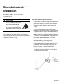
Place a piece of cardboard or cloth under the range during
installation to protect floors.
Electrical Requirements
Refer to rating label for more information. See the product
“Rating Label” in the section on Service in this manual.
We recommend that the range be installed with a
power cord set (not supplied with U.S. models). The
electrical rating of the power cord set must be 120/240 volt,
40 amperes minimum. The power cord set must be marked
“For Use with Ranges.” Always use a new power cord.
English 4
* Varies by location. Check local codes.
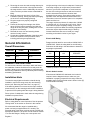
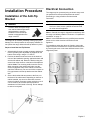
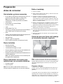
Electric Outlet Location
A flush mount 208/240 VAC dedicated circuit outlet is
required. Use the diagram below to make sure your
installation in properly prepared for the range. Note the
available space for the electrical outlet is shown in box (E)
in the illustration following.
Dimension Inches Centimeters
Height 36½” - 38” 92.7 cm - 96.6 cm
Width 31½” 80 cm
Depth 26¾” 68.1 cm
VOLTS
A/C
HZ RATING
KW
CIRCUIT
BREAKER
120/240 60 13.0 40 or 50 amps*
120/240 60 13.8 40 or 50 amps*
120/208 60 9.8 40 or 50 amps*
120/208 60 10.4 40 or 50 amps*
Verify that wiring to the house is adequate. Contact your
local utility company to verify that the present electric
service to your home is adequate. In some instances,
the size of the wiring to the house and service switch
must be increased to handle the electrical load
demanded by the range. Some wiring codes require a
separate circuit with separate disconnect switch and
fuses either in the main entrance panel or in a separate
switch and fuse box.
The range requires a minimum of a three-wire 120/240
or 120/208 volt, 40 - 50 amp, 60 Hz AC circuit. Check
local codes for proper amperage ratings. A four-wire
connection is preferred. Most local building regulations
and codes require that electrical wiring be done by
licensed electricians. Be sure to install your range
according to the electric codes in your region.
Electrical kW Rating
Ranges are dual rated for use on either 120/240 VAC or
120/208 VAC. Check the rating label for the kW rating.
Reference the kW rating in the table below to determine
amperage requirements.
___ 4. Move the range unit into place in front of the
installation opening, leaving the bottom packaging
on the unit to avoid damaging flooring.
___ 5. Plug the range into a properly configured
receptacle.
___ 6. Protect the flooring from damage, then lift the
range off of the bottom packaging and slide the
range all the way into place, making sure to route
the power cord correctly.
___ 7. Reinstall the oven door and warming drawer
removed in step 3 above.
___ 8. Consult the complete installation instructions and
follow the remainder of the procedures listed,
including performing an operation test.
___ 3. Removing the oven door and warming drawer prior
to installation reduces the unit weight and makes
the range easier to move. Additionally, the removal
of the oven door provides access to handhold for
lifting.

English 5
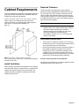
Cabinet Requirements
This unit is designed for installation near adjacent walls and
projecting surfaces constructed of combustible materials.
Prepare the countertop and cabinets.
Allow a minimum of 30" (76.2 cm) between cabinets
where range is to be installed. No side clearance is
required. Height is set by adjusting the range legs (see
later section, “Complete the installation” on
page 11).
Note: The slide-in range can also replace a
freestanding range. In this case, verify that the opening is
at least 30" (76.2 cm).
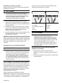
Install Ventilation
Bosch strongly recommends the installation of a ventilation
hood above this range. For most kitchens, a certified hood
rating of not less than 300 CFM is recommended. The
range hood must be installed according to instructions
furnished with the hood.
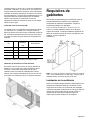
Required Clearance
These instructions were determined using standard
American cabinets. Standard base cabinets measure 36"
(91.4 cm) high x 25" (63.5 cm) deep. Cabinets over the
cooking surface and cabinets adjacent to those over the
cooking surface measure 13" (33 cm) deep from backwall.
If nonstandard cabinets are used, care should be taken to
alter dimensions accordingly.
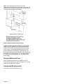
From cooktop to materials above:
• There must be a minimum clearance of 30” (762 mm)
between the top of the cooking surface and the bottom
of an unprotected wood or metal cabinet.
• Bosch recommends the minimum clearances shown in
the installation diagrams contained in this manual.
Clearances from non-combustible materials are not
certified by CSA. Clearances less than shown in the
installation diagrams must be approved by local codes
and/or by the local authority having jurisdiction.
From the cooking surface to side materials:
No clearance is required from unit walls to adjacent vertical
combustible walls on rear, right or left.
9 WARNING
To eliminate the risk of burns or fire by reaching over
heated surface units, cabinet storage space located
above the surface units should be avoided. If
cabinet storage is to be provided, the risk can be
reduced by installing a hood that projects
horizontally a minimum of 5" (12.7 cm) beyond the
bottom of the cabinet.

English 6
Note: Some cabinet finishes cannot survive the
temperatures allowed by safety standards, particularly self-
cleaning ovens; the cabinets may discolor or stain. This is
most noticeable with laminate cabinets.
Flame retardant materials bear the mark:
UNDERWRITERS LABORATORIES INC. CLASSIFIED
MINERAL AND FIBER BOARDS SURFACE BURNING
CHARACTERISTICS, followed by the flame spread and
smoke ratings. These designations are shown as “FHC
(Flame Spread/Smoke Developed)“. Materials with “O”
flame spread ratings are flame-retardant. Local codes may
allow other flame spread ratings. It is the responsibility of
the installer to ensure installation is in accordance with
these ratings.
Prepare Walls and Floor
Seal any holes in the walls or floor. Remove any ob-
structions (extra electrical or gas connections, etc.) so that
range will rest against wall properly.
Countertop Requirements
Countertops must be smooth and level.

English 7
Installation Procedure
Installation of the Anti-Tip
Bracket
The range can tip forward, potentially causing injury and
damage, if the anti-tip bracket is not properly installed. Do
not operate the range without the anti-tip bracket in place.
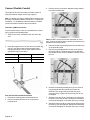
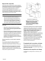
Steps to Install the Anti-Tip Bracket
1. Adjust height of range to match countertop height and
level it by rotating the adjustable leg supports on the
bottom of the range, using a 1¼" wrench.
2. Position the bracket as shown below in the back left
corner of the installation opening, against the back wall
and the left cabinet wall. Mount the bracket using two
screws into either the floor or the base of the adjacent
cabinet. Note: The mounting surface must be secure.
When mounting to the cabinet wall make sure the
screws engage the frame of the cabinet, not the thin
wall of the cabinet only. Do not use a block or spacer to
fill a gap between the anti-tip bracket and the cabinet
wall.
3. Secure the bracket with two screws to the floor or to
the base of the cabinet wall. Depending on the floor or
cabinet material, use wood or anchorless concrete
screws (included). Concrete screws require the use of
a 3/16" masonry bit. Screws should provide firm
attachment into solid wood or flooring. Do not attempt
to anchor into drywall.
Electrical Connection
The range may be connected using an electric range cord
(as specified in the Electrical Requirements section
preceeding) or using a flexible conduit electrical
connection.
Note: In Canada, the range is shipped from the factory with
the range cord already installed. Continue to “Complete the
installation” on page 11.
Note: It is recommended that only qualified persons add a
power cord or make electrical connections to this
appliance.
For installations other than those in Canada, connect the
range cord at the terminal block. Access the terminal block
by removing the cover in the lower left hand corner of the
range back panel.
9 WARNING
A child or adult can tip the range
over and be killed.Verify that the
anti-tip bracket is securely
installed. Ensure the anti-tip
bracket is engaged when the
range is moved.
9 WARNING
Do not use an extension cord. If the power supply
cord is too short, have a qualified electrician install
an outlet near the appliance.

English 8
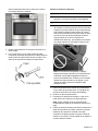
Install Strain Relief
Place strain relief in knockout below terminal block.
1. In the knockout panel below the terminal block, remove
the knockout that fits the strain relief that comes with
your range cord.
2. Feed the range cord through the hole and the strain
relief up to terminal block. Allow for slack in the cord
between the strain relief and terminal block.
3. Once the cord length/slack has been adjusted, attach
the strain relief per instructions included with strain
relief.
Tip: The knockout panel (below the terminal block) can be
removed from the range to install the strain relief. Remove
the panel from range, install strain relief in panel and
reattach. DO NOT remove entire range back panel.
Preparation for Power Connection
For installations where grounding through the neutral
conductor is prohibited: (a) disconnect the link from the
neutral, (b) use grounding terminal or lead to ground unit,
(c) connect neutral terminal to lead branch circuit neutral in
the usual manner. When the appliance is to be connected
by means of a cord kit, use 4-conductor cord for this
purpose.
Use only cord kits rated 125/250 volts, 40 amperes
(minimum), and labeled “For Use with Ranges”. Strain relief
provided with the cord must be installed per instructions
included with the cord.
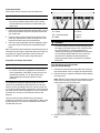
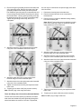
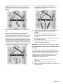
Four-wire Range Cord Connection
(Recommended Method)
1. Disconnect electrical power at breaker box. Remove
the terminal block cover to expose the terminal block.
2. Remove the top nut (has an attached locking washer)
from each post.
Note: DO NOT remove the second nut/washer on each
post; these must stay in place to anchor the internal
wiring attached to the terminal block.
3. Remove screw from the bottom end of the ground
strap.
9 WARNING
The strain relief provided with your range cord must
be properly installed. Strain reliefs vary. Carefully
read and follow the instructions included with your
strain relief.
9 WARNING
Risk of Electric Shock or Fire. Grounding through
the neutral conductor is prohibited for new branch-
circuit installations (1996 NEC), mobile homes, and
recreational vehicles, or in an area where local
codes prohibit grounding through the neutral
conductor.
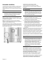
3-Wire Hookup 4-Wire Hookup
R= Red
W = White
GS = Grounding Strip
B = Black
R= Red
W = White
G = Green
B = Black
9 WARNING
To prevent electrical shock, the grounding prong on
the range cord should not be cut or removed under
any circumstances. It must be plugged into a
matching grounding type receptacle and connected
to a correctly polarized 240-Volt circuit. If there is
any doubt as to whether the wall receptacle is
properly grounded, have it checked by a qualified
electrician.

English 9
4. Remove the green grounding screw from the lower end
of the grounding strap. Remove the upper end of the
grounding strap from the center post of the junction
bar. Rotate the grounding strip (A) so that the wide end
is up and align the hole with the grounding hole below
the terminal block. Use the green grounding screw (B)
to attach the green wire (G) on top of grounding strap.
Tighten the grounding screw firmly, but do not
overtighten.
5. Attach the red wire to the left junction block terminal
using one of the nut/washers removed in step 2.
6. Attach the white wire to the center junction block
terminal using one of the nut/washer parts.
7. Attach the black wire to the right junction block terminal
using one of the nut/washer parts.
8. Tighten all connections securely and replace terminal
block cover.
9. Properly secure strain relief (see previous section).
Note: DO NOT plug in the range at this time.
Three-wire Range Cord Connection (Alternate Method)
The four-wire connection (above) is preferred, but where
local codes and ordinances permit grounding through the
neutral and where conversion to four-wire is impractical,
the unit may be connected to the power supply via a three-
wire connection.
1. Disconnect electrical power at breaker box.
2. Remove the terminal block cover to expose the
terminal block.
3. Remove the top nut (has an attached locking washer)
from each terminal post.
Note: DO NOT remove the second nut/washer on each
post. These must stay in place to anchor the internal
wiring attached to the terminal block.
4. Attach the white wire to the center junction block
terminal using one of the nut/washer parts.
5. Attach the red wire to the left junction block terminal
using one of the nut/washer parts removed in step 2.
6. Attach the black wire to the right junction block terminal
using one of the nut/washer parts.
7. Tighten all connections securely and replace terminal
block cover.
8. Properly secure strain relief (see previous section).
Note: DO NOT plug in range at this time.

English 10
Connect Flexible Conduit
The range can also be connected via flexible conduit. If
using this method, always use the lugs supplied.
Note: In Canada, the range is shipped from the factory with
the range cord already installed. Continue to “Complete the
installation”. For installations other than those in Canada,
connect the flexible conduit at the terminal block.
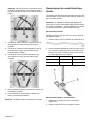
Terminal Lug/Wire Connection
In each instance where a wire is to be attached to a termi-
nal lug, perform the following steps:
1. Strip 3/8” (9.5 mm) of insulation from the end of the
wire.
2. Insert the stripped end of the wire into the terminal lug
(see A in the figure below) and then tighten each
clamping screw (see B in the figure below) with the
appropriate torque (see table).
Four-wire Flexible Conduit Connection
1. Disconnect electrical power at the breaker box.
2. Remove the terminal block cover to expose the
terminal block.
3. Remove the top nut (has an attached locking washer)
from each terminal post.
Note: DO NOT remove the second nut/washer on each
post. These must stay in place to anchor the internal wiring
attached to the terminal block.
4. Remove the green grounding screw from the lower end
of the grounding strap.
5. Remove the grounding strap from the center post on
the terminal block. The strap will not be needed with
the flexible conduit electric installation. Remove it from
the unit.
6. Attach the insulated grounding wire (G) to a terminal
lug (packaged with this manual) and secure the
terminal lug to the grounding hole with the green
grounding screw. Tighten the screw firmly, but do not
overtighten.
7. Attach the red wire (R) to a terminal lug and place the
terminal lug onto the left post. Replace the nut/washer
on the post and tighten to 20 in/lbs. (50.8 cm) of torque.
8. Attach the black wire (B) to a terminal lug and place the
terminal lug onto the right post. Replace the nut/washer
on the post and tighten to 20 in/lbs. (50.8 cm) of torque.
Wire Gauge Torque (in/lbs) Torque (Nm)
6353.95
8252.82

English 11
9. Properly secure the flexible conduit at knockout on
angle and at supply side junction box. The wiring is
now complete.
Note: DO NOT connect electrical power to the range at this
time.
Three-wire Flexible Conduit Connection
The four-wire connection is preferred, but where local
codes and ordinances permit grounding through neutral
and/or conversion to four-wire is impractical, the unit may
be connected to the power supply via a three-wire connec-
tion.
1. Disconnect electrical power at the breaker box.
2. Remove the terminal block cover to expose the
terminal block.
3. Remove the top nut, star washer, and round washer
from each post.
Note: DO NOT remove last round washer, last nut or inter-
nal wire leads.
4. Attach the red wire (R) to a terminal lug (packaged with
this manual) and place the terminal lug onto the left
post. Replace the nut/washer on the post and tighten to
20 in/lbs. (50.8 cm) of torque.
5. Attach the black wire (B) to a terminal lug and place the
terminal lug onto the right post. Replace the nut/washer
on the post and tighten to 20 in/lbs. (50.8 cm) of torque.
6. Attach the green wire (G) to a terminal lug and place
the terminal lug onto the center post. Replace the nut/
washer on the post and tighten to 20 in/lbs. (50.8 cm)
of torque.
7. Properly secure flexible conduit at knockout panel on
range and at supply side junction box. The wiring is
now complete.
Note: DO NOT connect electrical power to the range at this
time.
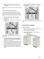
Complete the installation
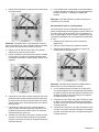
Adjust Leveling Legs
1. Make sure that the circuit breaker is off and then plug
range cord into the electrical outlet.
2. Line up range in front of opening.
3. Measure (A) back left corner of opening from floor to
the top of the countertop.

English 12
4. Measure the back left corner of the range to the bottom
of cooktop (B). Adjust leveling legs until this height is
the same as the corner dimension.
5. Repeat in the back right corner.
6. Use a 1¼ “ wrench to adjust front leveling legs so that
the height from the bottom of the cooktop to the floor
matches the height of the corresponding countertop
surface.
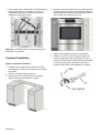
Slide Range into Opening
1. Remove oven door using the procedure “Removing the
Oven Door” on page 13 and lift the range off of the
packaging base.
2. Plug in the power cord.
3. Dampen countertop and floor at bottom of opening with
soapy water.
Note: Clean up any remaining soapy water
immediately after sliding the range in place.
4. Slide the range into the opening, being careful not to
damage countertops, floors, or the range door or
warming drawer front. Do not apply pressure to
cooktop when sliding into position. Be careful not to
crimp the flexible electrical connector.
5. Install the oven door using the procedure “Replacing
the Oven Door” on page 14.
9 CAUTION
Unit is heavy and requires at least two persons or
proper equipment to move.
NOTICE
To avoid risk of damage to the range oven door, do
not lift, push, or pull the range by holding the door
handle. After the door has been removed, reach
inside the top of the oven cavity to locate a ridged
area near the front of the oven. Take care not to
touch the oven heating element also located at the
top of the oven cavity, just behind the ridged area.
9 CAUTION
It is recommended to wear gloves and long sleeves
to protect hands and forearms from abrasion and
potential scratches during the lifting process. It is
also recommended to take off watches and jewelry
and to wear work shoes during installation for foot
protection.

English 13
Check Back of Range for Proper Installation
1. The cooktop should rest lightly on the countertop.
2. There should not be any gap between the countertop
and the cooktop; however, the weight of the range
must not rest on the countertop. Look under the range
to verify that both back legs are resting solidly on the
floor. Also verify that the left range leg is retained by the
anti-tip bracket.
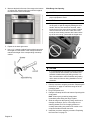
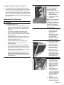
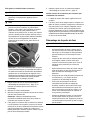
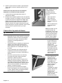
Removing the Oven Door
9 WARNING
When removing the door:
• Make sure oven is cool and power to the oven
has been turned off before removing the door.
Failure to do so could result in electrical shock
or burns.
• The oven door is heavy and parts of it are
fragile. Use both hands to remove the oven
door. The door front is glass. Handle carefully to
avoid breakage.
• Grasp only the sides of the oven door. Do not
grasp the handle as it may swing in your hand
and cause damage or injury.
• Failure to grasp the oven door firmly and
properly could result in personal injury or
product damage.
• To avoid injury from hinge bracket snapping
closed, be sure that both levers are securely in
place before removing the door. Also, do not
force door open or closed—the hinge could be
damaged and injury could result.
• Do not lay removed door on sharp or pointed
objects as this could break the glass. Lay on a
flat, smooth surface, positioned so that the door
cannot fall over.
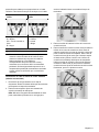
To help avoid injury or
damage be sure to read
the above WARNING
before attempting to
remove the oven door.
1. Open the oven door to
its fully open,
horizontal position.
2. Flip levers on hinges
toward you.
Note: It may be necessary
to use a tool, such as a
screwdriver, to gently pry
the upper part of the lever
away from the housing.
Take care to avoid scratch-
ing the housing.
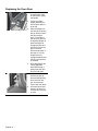
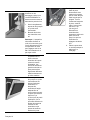
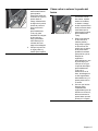
3. Bring both door hinge
levers to their fullest
down position as
shown in the
illustration. The left
and right door hinge
levers may differ
slightly but operate in
the same manner.
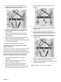
4. Close the oven door
until it catches on the
hinge stop levers,
locking the hinges at
the proper angle for
door removal. The
door will be open
about 7 inches at the
top. This takes the
spring tension off the
hinges so the door can
be easily lifted out.
5. The door is heavy.
Use both hands to
firmly grip it by the
sides. Do not grip the
door by the handle.
Maintaining the door
angle, lift the door
straight up
approximately ¾" to
unhook the hinges
from the slots and then
pull it out towards you
until the hinges are
clear of the oven
housing.
6. Place the door in a
convenient and stable
location for cleaning.

English 14
Replacing the Oven Door
1. Holding the door firmly
in both hands, grip it
on either side, not by
the handle.
2. Tilt the door back
slightly towards you
until it opens about 7"
at the top.
3. Slide the hinges into
the slots as far as they
will go and then lower
the door straight
down. The angle of
the door may need to
be adjusted slightly to
allow the hinges to
engage properly and
the door to lower into
place. The door
should lower about ¾"
and stop. If not, the
hinges have not
engaged properly and
the door could fall if it
is released.
4. Once both hinges are
fully engaged as
described in Step 3,
gently open the door
until it is fully open.
5. Push the levers on
both the hinges up
and forward until they
are locked into the
slot, flush with the
front of the oven body.
6. Close and open door
slowly to be sure it is
correctly and securely
in place.

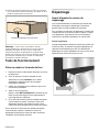
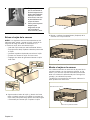
Removing the Warming Drawer
9 CAUTION
To prevent burns, do not remove drawer while hot.
Be sure the drawer is empty before removing.
English 15
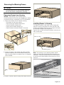
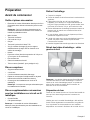
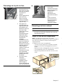
Removing Drawer from Housing
NOTICE: The following is the manufacturer’s
recommendations for removing and installing the drawer
to minimize the risk of damage to the PTO mechanism.
1.
Remove the drawer from the drawer housing.
▯ Pull drawer to fully open position.
▯ Press down right drawer release lever.
▯ Lift up left drawer release lever.
▯ Firmly pull the drawer straight out.
▯ Retract cabinet rails while drawer is removed.
2.
Grasp both sides of the drawer and pulling straight
and level, carefully remove the drawer housing. This
step may require light to moderate force to completely
remove drawer.
3.
Install or service (clean) housing with drawer removed.
-
0
8
)*()
@
.&%
13
00
'
0
/
0
''
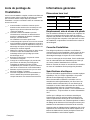
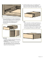
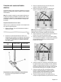
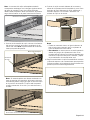
Installing Drawer to Housing
The slides mounted to each side of the housing wall
have two moving components, an inner rail and a ball
bearing carrier which need to be in the proper orientation
for accurate installation and alignment.
There is also a visible locking mechanism located at the
rear of each slide.
%DOO%HDULQJ&DUULHU
Note: The housing of your warming drawer should
match the image below identically before starting your
installation. The ball bearing carrier should be locked in
to the inner rail’s black plastic rail tip at the front of the
inner rail.
6OLGH,QQHU5DLO
/RFNLQJ0HFKDQLVP
%DOO%HDULQJ&DUULHU
6OLGH,QQHU5DLO

English 16
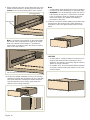
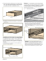
1.
With the drawer removed, set the slide inner rail to the
drawer locked position by pushing the slide inner rail
toward the rear of the housing until it locks in place.
Note: A moderate force pushing on the black plastic
ball carrier locking mechanism is required to set the
slide to the drawer locked position. The drawer is
locked when it remains in place and does not spring
back to the open position.
2.
Position the drawer assembly in front of the housing
assembly and align the rail (plastic rail tip) to the slide
ball carrier assembly. Keeping the drawer assembly
level and square to the housing, gently insert the
drawer to the housing assembly.
Notes
▯ A slight side-to-side wiggle motion may be required
to properly get the ball bearings to accurately align.
▯ Remember: You are attempting to align two sets of
ball bearings at this point. If more than a moderate
force is required to insert the drawer at this time,
remove the drawer and repeat the installation
procedure to this point.
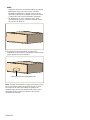
3.
Continue to insert the drawer keeping the drawer level
and square to the housing until a slight increase in
resistance is felt at the approximate position shown
below.
4MJEF*OOFS3BJM
-PDLJOH.FDIBOJTN
4MJEF*OOFS3BJMJTJOMPDLFEQPTJUJPO
NOTICES
▯ At this position, a slight increase in closure force is
required with several small increments of force
applied to the drawer to accurately align and set the
drawer for proper operation.
▯ An audible “click” should be heard when the drawer
is properly closed causing the drawer to lock in the
closed position.
La page est en cours de chargement...
La page est en cours de chargement...
La page est en cours de chargement...
La page est en cours de chargement...
La page est en cours de chargement...
La page est en cours de chargement...
La page est en cours de chargement...
La page est en cours de chargement...
La page est en cours de chargement...
La page est en cours de chargement...
La page est en cours de chargement...
La page est en cours de chargement...
La page est en cours de chargement...
La page est en cours de chargement...
La page est en cours de chargement...
La page est en cours de chargement...
La page est en cours de chargement...
La page est en cours de chargement...
La page est en cours de chargement...
La page est en cours de chargement...
La page est en cours de chargement...
La page est en cours de chargement...
La page est en cours de chargement...
La page est en cours de chargement...
La page est en cours de chargement...
La page est en cours de chargement...
La page est en cours de chargement...
La page est en cours de chargement...
La page est en cours de chargement...
La page est en cours de chargement...
La page est en cours de chargement...
La page est en cours de chargement...
La page est en cours de chargement...
La page est en cours de chargement...
La page est en cours de chargement...
La page est en cours de chargement...
La page est en cours de chargement...
La page est en cours de chargement...
La page est en cours de chargement...
La page est en cours de chargement...
La page est en cours de chargement...
La page est en cours de chargement...
La page est en cours de chargement...
La page est en cours de chargement...
La page est en cours de chargement...
La page est en cours de chargement...
La page est en cours de chargement...
La page est en cours de chargement...
-
 1
1
-
 2
2
-
 3
3
-
 4
4
-
 5
5
-
 6
6
-
 7
7
-
 8
8
-
 9
9
-
 10
10
-
 11
11
-
 12
12
-
 13
13
-
 14
14
-
 15
15
-
 16
16
-
 17
17
-
 18
18
-
 19
19
-
 20
20
-
 21
21
-
 22
22
-
 23
23
-
 24
24
-
 25
25
-
 26
26
-
 27
27
-
 28
28
-
 29
29
-
 30
30
-
 31
31
-
 32
32
-
 33
33
-
 34
34
-
 35
35
-
 36
36
-
 37
37
-
 38
38
-
 39
39
-
 40
40
-
 41
41
-
 42
42
-
 43
43
-
 44
44
-
 45
45
-
 46
46
-
 47
47
-
 48
48
-
 49
49
-
 50
50
-
 51
51
-
 52
52
-
 53
53
-
 54
54
-
 55
55
-
 56
56
-
 57
57
-
 58
58
-
 59
59
-
 60
60
-
 61
61
-
 62
62
-
 63
63
-
 64
64
-
 65
65
-
 66
66
-
 67
67
-
 68
68


dans d''autres langues
- English: Bosch HEIP056U Installation guide
- español: Bosch HEIP056U Guía de instalación