ESAB Inverter Arc Welder Model PS-3000 Manuel utilisateur
- Catégorie
- Système de soudage
- Taper
- Manuel utilisateur

Manual No. 0-2337
Instruction Manual
INVERTER
ARC
WELDER
MODEL PS-3000
• Plasma Arc Welding
October 23, 1998


Read and understand this entire Manual and your employer’s
safety practices before installing, operating, or servicing the
equipment.
While the information contained in this manual represents our
best judgement, Thermal Arc Corporation assumes no liability
for its use.
Thermal Arc
®
Model PS-3000 Inverter Arc Welder
Instruction Manual Number 0-2337
Published by:
Thermal Dynamics Corporation
Industrial Park No. 2
West Lebanon, New Hampshire, USA 03784
(603) 298-5711
Copyright 1992
Thermal Dynamics Corporation
All rights reserved.
Reproduction of this work, in whole or in part, without written
permission of the publisher is prohibited.
The publisher does not assume and hereby disclaims any liabil-
ity to any party for any loss or damage caused by any error or
omission in the Thermal Arc
®
Model PS-3000 Inverter Arc
Welder Instruction Manual, whether such error results from
negligence, accident, or any other cause.
October 23, 1998
WARNING
WARNING

TABLE OF CONTENTS
INTRODUCTION ............................................................................................................................i
Notes, Cautions and Warnings .................................................................................i
Important Safety Precautions ...................................................................................i
Publications .............................................................................................................ii
Note, Attention et Avertissement ............................................................................ iii
Precautions De Securite Importantes..................................................................... iii
Documents De Reference ...................................................................................... v
Declaration of Conformity .......................................................................................vi
Statement of Warranty........................................................................................... vii
SECTION 1: GENERAL INFORMATION ..................................................................................... 1
1.1 Specifications ................................................................................................... 1
1.2 Duty Cycle....................................................................................................... 2
SECTION 2: INSTALLATION ....................................................................................................... 3
2.1 Site Selection................................................................................................... 3
2.2 Transporting Methods ...................................................................................... 4
2.3 Weld Ooutput Connections .............................................................................. 5
2.4 Remote 14 Connections .................................................................................. 8
2.5 Electrical Input Connections .......................................................................... 10
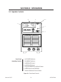
SECTION 3: OPERATION ......................................................................................................... 13
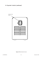
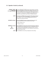
3.1 Operator Controls .......................................................................................... 13
3.2 Operating Precautions................................................................................... 18
3.3 Troubleshooting ............................................................................................. 19
SECTION 4: PARTS LIST..........................................................................................................21
4.01 Introduction.................................................................................................. 21
4.02 Ordering Information.................................................................................... 21
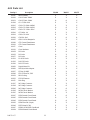
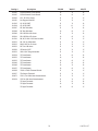
4.03 Parts List ..................................................................................................... 22

i INTRODUCTION
INTRODUCTION
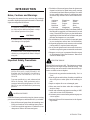
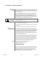
Notes, Cautions and Warnings
Throughout this manual, notes, cautions, and warnings
are used to highlight important information. These high-
lights are categorized as follows:
NOTE
An operation, procedure, or background informa-
tion which requires additional emphasis or is help-
ful in efficient operation of the system.
CAUTION
A procedure which, if not properly followed, may
cause damage to the equipment.
WARNING
A procedure which, if not properly followed, may
cause injury to the operator or others in the oper-
ating area.
Important Safety Precautions
WARNING
OPERATION AND MAINTENANCE OF
PLASMA ARC EQUIPMENT CAN BE DAN-
GEROUS AND HAZARDOUS TO YOUR
HEALTH.
To prevent possible injury, read, understand and
follow all warnings, safety precautions and in-
structions before using the equipment. Call 1-603-
298-5711 or your local distributor if you have any
questions.
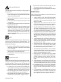
GASES AND FUMES
Gases and fumes produced during the plasma cutting
process can be dangerous and hazardous to your health.
• Keep all fumes and gases from the breathing area.
Keep your head out of the welding fume plume.
• Use an air-supplied respirator if ventilation is not
adequate to remove all fumes and gases.
• The kinds of fumes and gases from the plasma arc
depend on the kind of metal being used, coatings
on the metal, and the different processes. You must
be very careful when cutting or welding any met-
als which may contain one or more of the follow-
ing:
Antimony Chromium Mercury
Arsenic Cobalt Nickel
Barium Copper Selenium
Beryllium Lead Silver
Cadmium Manganese Vanadium
• Always read the Material Safety Data Sheets (MSDS)
that should be supplied with the material you are
using. These MSDSs will give you the information
regarding the kind and amount of fumes and gases
that may be dangerous to your health.
• For information on how to test for fumes and gases
in your workplace, refer to item 1 in Publications.
• Use special equipment, such as water or down draft
cutting tables, to capture fumes and gases.
• Do not use the plasma torch in an area where com-
bustible or explosive gases or materials are located.
• Phosgene, a toxic gas, is generated from the vapors
of chlorinated solvents and cleansers. Remove all
sources of these vapors.
ELECTRIC SHOCK
Electric Shock can injure or kill. The plasma arc process
uses and produces high voltage electrical energy. This
electric energy can cause severe or fatal shock to the op-
erator or others in the workplace.
• Never touch any parts that are electrically “live” or
“hot.”
• Wear dry gloves and clothing. Insulate yourself from
the work piece or other parts of the welding cir-
cuit.
• Repair or replace all worn or damaged parts.
• Extra care must be taken when the workplace is
moist or damp.
• Install and maintain equipment according to NEC
code, refer to item 9 in Publications.
• Disconnect power source before performing any ser-
vice or repairs.
• Read and follow all the instructions in the Operat-
ing Manual.

INTRODUCTION ii
FIRE AND EXPLOSION
Fire and explosion can be caused by hot slag, sparks, or
the plasma arc.
• Be sure there is no combustible or flammable mate-
rial in the workplace. Any material that cannot be
removed must be protected.
• Ventilate all flammable or explosive vapors from
the workplace.
• Do not cut or weld on containers that may have held
combustibles.
• Provide a fire watch when working in an area where
fire hazards may exist.
• Hydrogen gas may be formed and trapped under
aluminum workpieces when they are cut under-
water or while using a water table. DO NOT cut
aluminum alloys underwater or on a water table
unless the hydrogen gas can be eliminated or dis-
sipated. Trapped hydrogen gas that is ignited will
cause an explosion.
NOISE
Noise can cause permanent hearing loss. Plasma arc pro-
cesses can cause noise levels to exceed safe limits. You
must protect your ears from loud noise to prevent per-
manent loss of hearing.
• To protect your hearing from loud noise, wear pro-
tective ear plugs and/or ear muffs. Protect others
in the workplace.
• Noise levels should be measured to be sure the deci-
bels (sound) do not exceed safe levels.
• For information on how to test for noise, see item 1
in Publications.
PLASMA ARC RAYS
Plasma Arc Rays can injure your eyes and burn your skin.
The plasma arc process produces very bright ultra violet
and infra red light. These arc rays will damage your
eyes and burn your skin if you are not properly protected.
• To protect your eyes, always wear a welding hel-
met or shield. Also always wear safety glasses with
side shields, goggles or other protective eye wear.
• Wear welding gloves and suitable clothing to pro-
tect your skin from the arc rays and sparks.
• Keep helmet and safety glasses in good condition.
Replace lenses when cracked, chipped or dirty.
• Protect others in the work area from the arc rays.
Use protective booths, screens or shields.
• Use the shade of lens as recommended in Publica-
tions, item 4.
Publications
Refer to the following standards or their latest revisions
for more information:
1. OSHA, SAFETY AND HEALTH STANDARDS,
29CFR 1910, obtainable from the Superintendent of
Documents, U.S. Government Printing Office, Wash-
ington, D.C. 20402
2. ANSI Standard Z49.1, SAFETY IN WELDING AND
CUTTING, obtainable from the American Welding
Society, 550 N.W. LeJeune Rd, Miami, FL 33126
3. NIOSH, SAFETY AND HEALTH IN ARC WELD-
ING AND GAS WELDING AND CUTTING, obtain-
able from the Superintendent of Documents, U.S.
Government Printing Office, Washington, D.C. 20402
4. ANSI Standard Z87.1, SAFE PRACTICES FOR OC-
CUPATION AND EDUCATIONAL EYE AND FACE
PROTECTION, obtainable from American National
Standards Institute, 1430 Broadway, New York, NY
10018
5. ANSI Standard Z41.1, STANDARD FOR MEN’S
SAFETY-TOE FOOTWEAR, obtainable from the
American National Standards Institute, 1430 Broad-
way, New York, NY 10018
6. ANSI Standard Z49.2, FIRE PREVENTION IN THE
USE OF CUTTING AND WELDING PROCESSES,
obtainable from American National Standards Insti-
tute, 1430 Broadway, New York, NY 10018
7. AWS Standard A6.0, WELDING AND CUTTING
CONTAINERS WHICH HAVE HELD COMBUS-
TIBLES, obtainable from American Welding Society,
550 N.W. LeJeune Rd, Miami, FL 33126
8. NFPA Standard 51, OXYGEN-FUEL GAS SYSTEMS
FOR WELDING, CUTTING AND ALLIED PRO-
CESSES, obtainable from the National Fire Protec-
tion Association, Batterymarch Park, Quincy, MA
02269
9. NFPA Standard 70, NATIONAL ELECTRICAL
CODE, obtainable from the National Fire Protection
Association, Batterymarch Park, Quincy, MA 02269
10. NFPA Standard 51B, CUTTING AND WELDING
PROCESSES, obtainable from the National Fire Pro-
tection Association, Batterymarch Park, Quincy, MA
02269
11. CGA Pamphlet P-1, SAFE HANDLING OF COM-
PRESSED GASES IN CYLINDERS, obtainable from
the Compressed Gas Association, 1235 Jefferson
Davis Highway, Suite 501, Arlington, VA 22202

iii INTRODUCTION
12. CSA Standard W117.2, CODE FOR SAFETY IN
WELDING AND CUTTING, obtainable from the Ca-
nadian Standards Association, Standards Sales, 178
Rexdale Boulevard, Rexdale, Ontario, Canada M9W
1R3
13. NWSA booklet, WELDING SAFETY BIBLIOGRA-
PHY obtainable from the National Welding Supply
Association, 1900 Arch Street, Philadelphia, PA 19103
14. American Welding Society Standard AWSF4.1, REC-
OMMENDED SAFE PRACTICES FOR THE PREPA-
RATION FOR WELDING AND CUTTING OF CON-
TAINERS AND PIPING THAT HAVE HELD
HAZARDOUS SUBSTANCES, obtainable from the
American Welding Society, 550 N.W. LeJeune Rd,
Miami, FL 33126
15. ANSI Standard Z88.2, PRACTICE FOR RESPIRA-
TORY PROTECTION, obtainable from American
National Standards Institute, 1430 Broadway, New
York, NY 10018
Note, Attention et Avertissement
Dans ce manuel, les mots “note,” “attention,” et
“avertissement” sont utilisés pour mettre en relief des
informations à caractère important. Ces mises en relief
sont classifiées comme suit :
NOTE
Toute opération, procédure ou renseignement
général sur lequel il importe d’insister davantage
ou qui contribue à l’efficacité de fonctionnement
du système.
ATTENTION
Toute procédure pouvant résulter
l’endommagement du matériel en cas de non-
respect de la procédure en question.
AVERTISSEMENT
Toute procédure pouvant provoquer des blessures
de l’opérateur ou des autres personnes se trouvant
dans la zone de travail en cas de non-respect de la
procédure en question.
Precautions De Securite Importantes
AVERTISSEMENT
L’OPÉRATION ET LA MAINTENANCE DU
MATÉRIEL DE SOUDAGE À L’ARC AU JET
DE PLASMA PEUVENT PRÉSENTER DES
RISQUES ET DES DANGERS DE SANTÉ.
Il faut communiquer aux opérateurs et au person-
nel TOUS les dangers possibles. Afin d’éviter les
blessures possibles, lisez, comprenez et suivez tous
les avertissements, toutes les précautions de
sécurité et toutes les consignes avant d’utiliser le
matériel. Composez le + 603-298-5711 ou votre
distributeur local si vous avez des questions.
FUMÉE et GAZ
La fumée et les gaz produits par le procédé de jet de
plasma peuvent présenter des risques et des dangers de
santé.
• Eloignez toute fumée et gaz de votre zone de respi-
ration. Gardez votre tête hors de la plume de fumée
provenant du chalumeau.
• Utilisez un appareil respiratoire à alimentation en
air si l’aération fournie ne permet pas d’éliminer la
fumée et les gaz.
• Les sortes de gaz et de fumée provenant de l’arc de
plasma dépendent du genre de métal utilisé, des
revêtements se trouvant sur le métal et des différents
procédés. Vous devez prendre soin lorsque vous
coupez ou soudez tout métal pouvant contenir un
ou plusieurs des éléments suivants:
antimoine cadmium mercure
argent chrome nickel
arsenic cobalt plomb
baryum cuivre sélénium
béryllium manganèse vanadium
• Lisez toujours les fiches de données sur la sécurité
des matières (sigle américain “MSDS”); celles-ci
devraient être fournies avec le matériel que vous
utilisez. Les MSDS contiennent des renseignements
quant à la quantité et la nature de la fumée et des
gaz pouvant poser des dangers de santé.
• Pour des informations sur la manière de tester la
fumée et les gaz de votre lieu de travail, consultez
l’article 1 et les documents cités à la page v.

INTRODUCTION iv
• Utilisez un équipement spécial tel que des tables de
coupe à débit d’eau ou à courant descendant pour
capter la fumée et les gaz.
• N’utilisez pas le chalumeau au jet de plasma dans
une zone où se trouvent des matières ou des gaz
combustibles ou explosifs.
• Le phosgène, un gaz toxique, est généré par la fumée
provenant des solvants et des produits de nettoyage
chlorés. Eliminez toute source de telle fumée.
CHOC ELECTRIQUE
Les chocs électriques peuvent blesser ou même tuer. Le
procédé au jet de plasma requiert et produit de l’énergie
électrique haute tension. Cette énergie électrique peut
produire des chocs graves, voire mortels, pour l’opérateur
et les autres personnes sur le lieu de travail.
• Ne touchez jamais une pièce “sous tension” ou
“vive”; portez des gants et des vêtements secs.
Isolez-vous de la pièce de travail ou des autres par-
ties du circuit de soudage.
• Réparez ou remplacez toute pièce usée ou
endommagée.
• Prenez des soins particuliers lorsque la zone de tra-
vail est humide ou moite.
• Montez et maintenez le matériel conformément au
Code électrique national des Etats-Unis. (Voir la
page v, article 9.)
• Débranchez l’alimentation électrique avant tout tra-
vail d’entretien ou de réparation.
• Lisez et respectez toutes les consignes du Manuel
de consignes.
INCENDIE ET EXPLOSION
Les incendies et les explosions peuvent résulter des scories
chaudes, des étincelles ou de l’arc de plasma. Le procédé
à l’arc de plasma produit du métal, des étincelles, des
scories chaudes pouvant mettre le feu aux matières com-
bustibles ou provoquer l’explosion de fumées
inflammables.
• Soyez certain qu’aucune matière combustible ou in-
flammable ne se trouve sur le lieu de travail.
Protégez toute telle matière qu’il est impossible de
retirer de la zone de travail.
• Procurez une bonne aération de toutes les fumées
inflammables ou explosives.
• Ne coupez pas et ne soudez pas les conteneurs ayant
pu renfermer des matières combustibles.
• Prévoyez une veille d’incendie lors de tout travail
dans une zone présentant des dangers d’incendie.
• Le gas hydrogène peut se former ou s’accumuler
sous les pièces de travail en aluminium lorsqu’elles
sont coupées sous l’eau ou sur une table d’eau. NE
PAS couper les alliages en aluminium sous l’eau ou
sur une table d’eau à moins que le gas hydrogène
peut s’échapper ou se dissiper. Le gas hydrogène
accumulé explosera si enflammé.
RAYONS D’ARC DE PLASMA
Les rayons provenant de l’arc de plasma peuvent blesser
vos yeux et brûler votre peau. Le procédé à l’arc de plasma
produit une lumière infra-rouge et des rayons ultra-vio-
lets très forts. Ces rayons d’arc nuiront à vos yeux et
brûleront votre peau si vous ne vous protégez pas
correctement.
• Pour protéger vos yeux, portez toujours un casque
ou un écran de soudeur. Portez toujours des lunettes
de sécurité munies de parois latérales ou des lu-
nettes de protection ou une autre sorte de protec-
tion oculaire.
• Portez des gants de soudeur et un vêtement
protecteur approprié pour protéger votre peau
contre les étincelles et les rayons de l’arc.
• Maintenez votre casque et vos lunettes de protec-
tion en bon état. Remplacez toute lentille sale ou
comportant fissure ou rognure.
• Protégez les autres personnes se trouvant sur la zone
de travail contre les rayons de l’arc en fournissant
des cabines ou des écrans de protection.
• Respectez le teint de lentille recommandé dans le
article 4, page 5.
BRUIT
Le bruit peut provoquer une perte permanente de l’ouïe.
Les procédés de soudage à l’arc de plasma peuvent
provoquer des niveaux sonores supérieurs aux limites
normalement acceptables. Vous dú4ez vous protéger les
oreilles contre les bruits forts afin d’éviter une perte
permanente de l’ouïe.
• Pour protéger votre ouïe contre les bruits forts, portez
des tampons protecteurs et/ou des protections
auriculaires. Protégez également les autres
personnes se trouvant sur le lieu de travail.
• Il faut mesurer les niveaux sonores afin d’assurer
que les décibels (le bruit) ne dépassent pas les
niveaux sûrs.

v INTRODUCTION
• Pour des renseignements sur la manière de tester le
bruit, consultez l’article 1, page v.
Documents De Reference
Consultez les normes suivantes ou les révisions les plus
récentes ayant été faites à celles-ci pour de plus amples
renseignements :
1. OSHA, NORMES DE SÉCURITÉ DU TRAVAIL ET
DE PROTECTION DE LA SANTÉ, 29CFR 1910,
disponible auprès du Superintendent of Docu-
ments, U.S. Government Printing Office, Washing-
ton, D.C. 20402
2. Norme ANSI Z49.1, LA SÉCURITÉ DES
OPÉRATIONS DE COUPE ET DE SOUDAGE,
disponible auprès de la Société Américaine de
Soudage (American Welding Society), 550 N.W.
LeJeune Rd., Miami, FL 33126
3. NIOSH, LA SÉCURITÉ ET LA SANTÉ LORS DES
OPÉRATIONS DE COUPE ET DE SOUDAGE À
L’ARC ET AU GAZ, disponible auprès du Superin-
tendent of Documents, U.S. Government Printing
Office, Washington, D.C. 20402
4. Norme ANSI Z87.1, PRATIQUES SURES POUR LA
PROTECTION DES YEUX ET DU VISAGE AU
TRAVAIL ET DANS LES ECOLES, disponible de
l’Institut Américain des Normes Nationales (Ameri-
can National Standards Institute), 1430 Broadway,
New York, NY 10018
5. Norme ANSI Z41.1, NORMES POUR LES
CHAUSSURES PROTECTRICES, disponible auprès
de l’American National Standards Institute, 1430
Broadway, New York, NY 10018
6. Norme ANSI Z49.2, PRÉVENTION DES
INCENDIES LORS DE L’EMPLOI DE PROCÉDÉS
DE COUPE ET DE SOUDAGE, disponible auprès
de l’American National Standards Institute, 1430
Broadway, New York, NY 10018
7. Norme A6.0 de l’Association Américaine du
Soudage (AWS), LE SOUDAGE ET LA COUPE DE
CONTENEURS AYANT RENFERMÉ DES
PRODUITS COMBUSTIBLES, disponible auprès de
la American Welding Society, 550 N.W. LeJeune Rd.,
Miami, FL 33126
8. Norme 51 de l’Association Américaine pour la Pro-
tection contre les Incendies (NFPA), LES SYSTEMES
À GAZ AVEC ALIMENTATION EN OXYGENE
POUR LE SOUDAGE, LA COUPE ET LES
PROCÉDÉS ASSOCIÉS, disponible auprès de la
National Fire Protection Association, Batterymarch
Park, Quincy, MA 02269
9. Norme 70 de la NFPA, CODE ELECTRIQUE NA-
TIONAL, disponible auprès de la National Fire Pro-
tection Association, Batterymarch Park, Quincy, MA
02269
10. Norme 51B de la NFPA, LES PROCÉDÉS DE
COUPE ET DE SOUDAGE, disponible auprès de
la National Fire Protection Association,
Batterymarch Park, Quincy, MA 02269
11. Brochure GCA P-1, LA MANIPULATION SANS
RISQUE DES GAZ COMPRIMÉS EN CYLINDRES,
disponible auprès de l’Association des Gaz
Comprimés (Compressed Gas Association), 1235
Jefferson Davis Highway, Suite 501, Arlington, VA
22202
12. Norme CSA W117.2, CODE DE SÉCURITÉ POUR
LE SOUDAGE ET LA COUPE, disponible auprès
de l’Association des Normes Canadiennes, Stan-
dards Sales, 178 Rexdale Boulevard, Rexdale,
Ontario, Canada, M9W 1R3
13. ivret NWSA, BIBLIOGRAPHIE SUR LA SÉCURITÉ
DU SOUDAGE, disponible auprès de l’Association
Nationale de Fournitures de Soudage (National
Welding Supply Association), 1900 Arch Street,
Philadelphia, PA 19103
14. Norme AWSF4.1 de l’Association Américaine de
Soudage, RECOMMANDATIONS DE PRATIQUES
SURES POUR LA PRÉPARATION À LA COUPE
ET AU SOUDAGE DE CONTENEURS ET TUYAUX
AYANT RENFERMÉ DES PRODUITS
DANGEREUX , disponible auprès de la American
Welding Society, 550 N.W. LeJeune Rd., Miami, FL
33126
15. Norme ANSI Z88.2, PRATIQUES DE PROTEC-
TION RESPIRATOIRE, disponible auprès de
l’American National Standards Institute, 1430
Broadway, New York, NY 10018

INTRODUCTION vi
Declaration of Conformity
Manufacturer:
Thermal Arc, Inc.
Address: 2200 Corporate Drive
Troy, Ohio 45373-1085
USA
The equipment described in this manual conforms to all applicable aspects and regulations of the ‘Low Voltage Direc-
tive’ (European Council Directive 73/23/EEC as amended by Council Directive 93/68/EEC) and to the National leg-
islation for the enforcement of this Directive.
Serial numbers are unique with each individual piece of equipment and details description, parts used to manufacture
a unit and date of manufacture.
National Standard and Technical Specifications
The product is designed and manufactured to a number of standards and technical requirements among them are:
* CSA (Canadian Standards Association) standard C22.2 number 60 for Arc welding equipment.
* UL (Underwriters Laboratory) rating 94VO flammability testing for all printed-circuit boards used.
* ISO/IEC 60974-1 (BS 638-PT10) (EN 60 974-1) applicable to welding equipment and associated accessories.
* Extensive product design verification is conducted at the manufacturing facility as part of the routine design and
manufacturing process. This is to ensure the product is safe, when used according to instructions in this manual and
related industry standards, and performs as specified. Rigorous testing is incorporated into the manufacturing
process to ensure the manufactured product meets or exceeds all design specifications.
Thermal Dynamics has been manufacturing products for more than 30 years, and will continue to achieve excellence in our
area of manufacture.
Manufacturers responsible representative: David Ashworth
Vice President & Managing Director
Thermadyne Europe
Chorley England.

vii INTRODUCTION
Statement of Warranty
LIMITED WARRANTY: Thermal Arc
®
, Inc., A Thermadyne Company, warrants that its products will be free of defects in
workmanship or material. Should any failure to conform to this warranty appear within the time period applicable to the
Thermal Arc products as stated below, Thermal Arc shall, upon notification thereof and substantiation that the product has been
stored, installed, operated, and maintained in accordance with Thermal Arc’s specifications, instructions, recommendations and
recognized standard industry practice, and not subject to misuse, repair, neglect, alteration, or accident, correct such defects by
suitable repair or replacement, at Thermal Arc’s sole option, of any components or parts of the product determined by Thermal
Arc to be defective.
THERMAL ARC MAKES NO OTHER WARRANTY, EXPRESS OR IMPLIED. THIS WARRANTY IS EXCLUSIVE AND IN
LIEU OF ALL OTHERS, INCLUDING, BUT NOT LIMITED TO ANY WARRANTY OF MERCHANTABILITY OR FITNESS
FOR ANY PARTICULAR PURPOSE.
LIMITATION OF LIABILITY: Thermal Arc shall not under any circumstances be liable for special or consequential damages,
such as, but not limited to, damage or loss of purchased or replacement goods, or claims of customers of distributor (hereinafter
“Purchaser”) for service interruption. The remedies of the Purchaser set forth herein are exclusive and the liability of Thermal
Arc with respect to any contract, or anything done in connection therewith such as the performance or breach thereof, or from
the manufacture, sale, delivery, resale, or use of any goods covered by or furnished by Thermal Arc whether arising out of
contract, negligence, strict tort, or under any warranty, or otherwise, shall not, except as expressly provided herein, exceed the
price of the goods upon which such liability is based. No employee, agent, or representative of Thermal Arc is authorized to
change this warranty in any way or grant any other warranty.
THIS WARRANTY BECOMES INVALID IF REPLACEMENT PARTS OR ACCESSORIES ARE USED WHICH IN THER-
MAL ARC’S SOLE JUDEGMENT MAY IMPAIR THE SAFETY OR PERFORMANCE OF ANY THERMAL ARC PRODUCT.
THIS WARRANTY IS INVALID IF THE PRODUCT IS SOLD BY NON-AUTHORIZED PERSONS.
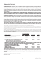
Except with regards to the products listed below, this warranty shall remain effective three (3) years from the date Thermal Arc’s
authorized distributor delivers the product to Purchaser, but in no event more than (4) years from the date Thermal Arc delivers
the product to the authorized distributor.
Shorter warranty periods apply to the products listed below. On these products, the warranty is effective for the time stated
below beginning on the date that the authorized distributor delivers the products to the Purchaser. Notwithstanding the forego-
ing, in no event shall the warranty period extend more than the time stated plus one year from the date Thermal Arc delivered
the product to the authorized distributor.
PLASMA WELDING/
POWER SUPPLIES VIKING/GENERATORS INVERTERS LABOR
MAIN POWER MAGNETICS (STATIC & ROTATING) 3 YEARS 2 YEARS 1 YEAR
ORIGINAL MAIN POWER RECTIFIER 3 YEARS 2 YEARS 1 YEAR
CONTROL PC BOARD 3 YEARS 2 YEARS 1 YEAR
ALL OTHER CIRCUITS AND COMPONENTS INCLUDING 1 YEAR 1 YEAR 1 YEAR
BUT NOT LIMITED TO, CONTACTORS, RELAYS,
SOLENOIDS, PUMPS, POWER SWITCHING SEMI-CONDUCTORS
ENGINES: ENGINES ARE NOT WARRANTED BY THERMAL ARC, ALTHOUGH MOST ARE WARRANTED BY THE
ENGINE MANUFACTURER. SEE THE ENGINE MANUFACTORS WARRANTY FOR DETAILS.
CONSOLES, CONTROL EQUIPMENT, HEAT 1 YEAR 1 YEAR 1 YEAR
EXCHANGES, AND ACCESSORY EQUIPMENT
TORCH AND LEADS 180 DAYS 180 DAYS 180 DAYS
REPAIR/REPLACEMENT PARTS 90 DAYS 90 DAYS 90 DAYS
Warranty repairs or replacement claims under this limited warranty must be submitted to Thermal Arc by an authorized Ther-
mal Arc® repair facility within thirty (30) days of the repair. No transportation costs of any kind will be paid under this war-
ranty. Transportation charges to send products to an authorized warranty repair facility shall be the responsibility of the cus-
tomer. All returned goods shall be at the customer’s risk and expense. This warranty supersedes all previous Thermal Arc
warranties.
Thermal Arc® is a Registered Trademark of Thermadyne.
Effective May 1, 1997

INTRODUCTION viii

Manual 0-2337 1 GENERAL INFORMATION
SECTION 1: GENERAL INFORMATION
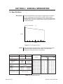
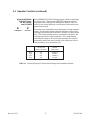
1.1 Specifications
The Model PS-3000 is a three-phase or single-phase (if derated)
DC arc welding power source with constant current output
characteristics. This unit is designed for use with the Plasma Arc
Welding (PAW) process. A digital meter displaying amperes and
voltage is standard.
Description
Table 1-A Unit Specifications
Figure 1-A Volt-Ampere Curve
The volt-ampere curve shows the voltage and amperage output
capabilities of the welding power source. Curves of other
settings will fall between the curves shown.
NOTE
Input Data At Rated Load No Load
50/60 Hz Output Output
Amps KVA KW Amps KVA KW
208 VAC 1-Phase 48 10 7 2.5 0.5 0.3
208 VAC 3-Phase 39 14 11 1.5 0.5 0.3
230 VAC 1-Phase 43 10 7 2.0 0.5 0.3
230 VAC 3-Phase 35 14 11 1.0 0.5 0.3
460 VAC 1-Phase 21 10 7 1.0 0.5 0.3
460 VAC 3-Phase 18 14 11 0.5 0.5 0.3
575 VAC 3-Phase 14 14 11 0.5 0.5 0.3
380 VAC 3-Phase 21 14 11 1.0 0.5 0.3
400 VAC 3-Phase 20 14 11 1.0 0.5 0.3
415 VAC 3-Phase 19 14 11 0.5 0.5 0.3
Rated Output Single-Phase Three-Phase
Amperes 210 300
Volts 28 32
Duty Cycle 60% 60%
Range (Min-Max):
Amperes 5-260 5-350
Volts 10-30 10-36
Maximum OCV: 70
Input Data 50/60 Hz
Width 10.88 in (276 mm)
Height 16.75 in (425 mm)
Length 18.31 in (465 mm)
Weight (with Cable) 82 lbs (37.2 kg)
OCV Less than 80V C.C.
AMPS
5 150 350
V
OLTS

GENERAL INFORMATION 2 Manual 0-2337
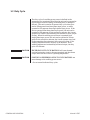
The duty cycle of a welding power source is defined as the
percentage of a ten minute period that the unit can be operated at
a given output without causing overheating and/or damage to
the unit. This unit is rated at 60 percent duty cycle when oper-
ated at 300 amperes from three-phase input power, or when
operated at 210 amperes from single-phase input power. If the
unit is operated from three-phase input power, the unit can be
operated at 300 amperes for six consecutive minutes, but it must
operate at no load for the remaining four minutes to allow proper
cooling. When the welding power source is operated from
single-phase input power, the unit can be operated at 210 am-
peres for six consecutive minutes, but it must operate at no load
for the remaining four minutes to allow proper cooling. If the
welding amperes decrease, the duty cycle increases. If the
welding amperes are increased beyond rated output, the duty
cycle will decrease.
EXCEEDING DUTY CYCLE RATINGS will cause thermal
overload protection circuit to become energized and shut down
output until unit has cooled to operating temperature.
CONTINUAL EXCEEDING OF DUTY CYCLE RATINGS can
cause damage to the welding power source.
• Do not exceed indicated duty cycles.
1.2 Duty Cycle
CAUTION
CAUTION

Manual 0-2337 3 INSTALLATION
SECTION 2: INSTALLATION
2.1 Site Selection
Select an installation site which provides the following:
1. Correct input power supply (see unit nameplate)
2. Shielding gas supply (if applicable)
3. Water supply (if applicable)
4. Adequate ventilation and fresh air supply
5. No flammables
6. A clean and dry area
7. Proper temperature that avoids extremes of heat or cold
8. Proper airflow around unit
FIRE OR EXPLOSION can result from placing unit on or over
combustible surfaces. RESTRICTED AIRFLOW can cause
overheating and possible damage to internal parts.
• Do not locate unit over combustible surfaces.
• Maintain at least 3 inches (76 mm) of space from sides of unit, 6
inches (152 mm) from rear, and open, unrestricted access to
ambient air at front of unit.
• Do not place any filtering device over the intake air passages
that provide airflow for cooling this equipment.
Warranty is subject to being voided if any type of filtering device
is used at intake air passages.
WARNING
NOTE

INSTALLATION 4 Manual 0-2337
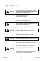
2.2 Transporting Methods
This unit is equipped with two handles for carrying purposes.
ELECTRIC SHOCK can kill.
• Do not touch live electrical parts.
• Disconnect input power conductors from de-energized supply
line before moving welding power source.
FALLING EQUIPMENT can cause serious personal injury and
equipment damage.
• Have two persons of adequate physical strength lift unit.
• Use hand cart or similar device of adequate capacity.
• If using a fork lift vehicle, place and secure unit on a proper
skid before transporting.
WARNING
WARNING

Manual 0-2337 5 INSTALLATION
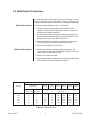
2.3 Weld Ooutput Connections
To obtain full rated output from this unit, it is necessary to select,
prepare, and install proper weld cables. Failure to comply in any
of these areas may result in unsatisfactory welding performance.
Use the following guidelines to select weld cables:
1. Use the shortest possible cables, and place cables close
together. Excessive cable lengths may reduce or cause unit
overload due to added resistance.
2. Use weld cable with an insulation voltage rating equal to or
greater than the maximum open circuit voltage (OCV) of the
welding power source (see Table 2-A below).
3. Select weld cable size according to maximum weld output
and total length of connecting cables in weld circuit.
4. Do not use damaged or frayed cables.
1. Install terminal lugs of adequate amperage capacity and
correct stud size onto ends of cables that connect to the work
clamp and electrode holder or torch.
2. Install work clamp onto cable.
3. Install supplied male connectors onto remaining ends of both
cables (refer to Connector Installation, page 6).
Weld Cable Selection
Weld Cable Preparation
Table 2-A Weld Cable Sizes
Maximum Total Cable Length in Weld Circuit
Welding Under 100 ft 150 ft 200 ft 250 ft 300 ft 250 ft 400 ft
Amperes (Under 30 m) (45 m) (60 m) (70 m) (90 m) (105 m) (120 m)
10-60% 60-100% 10-100%
Duty Cycle Duty Cycle Duty Cycle
100 4 4 4 3 2 1 1/0 1/0
150 3 3 2 1 1/0 2/0 3/0 3/0
200 3 2 1 1/0 2/0 3/0 4/0 4/0
250 2 1 1/0 2/0 3/0 4/0 2-2/0 2-2/0
300 1 1/0 2/0 3/0 4/0 2-2/0 2-3/0 2-3/0
400 1/0 2/0 3/0 4/0 2-2/0 2-3/0 2-4/0 2-4/0

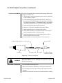
INSTALLATION 6 Manual 0-2337
To install the supplied male connectors onto proper cables, refer
to Figure 2-A below and:
1. Obtain cable of desired length and proper size for installation
(refer to Table A, page 5).
2. If the installation requires cable larger than 3/0 AWG, pre-
pare one end of 3/0 AWG pigtail no longer than 2 ft (0.61 m)
for connector installation. The remaining end of the pigtail is
connected to the main run of 3/0 AWG or larger weld cable.
3. Push weld cable through insulator as shown.
4. Remove 1 in (25 mm) of insulation from end of cable.
5. Install supplied sleeve on stripped end of cable.
6. Insert cable with sleeve into connector body so that cable is
snug and against bottom of connector body.
7. Install and tighten set screw with supplied hex wrench to
secure connector body onto cable.
8. Push insulator onto connector body to cover set screw.
2.3 Weld Output Connections (continued)
Connector Installation
ELECTRIC SHOCK can kill. ARCING can burn skin or damage
electrical connections.
• Do not touch live electrical parts.
• Shut down unit before making any weld output connections.
• Do not change position of the welding cable connectors while
welding.
• Be sure the connectors are secure in receptacles before welding.
WARNING
Weld Cable Connections
Figure 2-A Connector Installation
Strip insulation approx. 1 in from end
Insulator Weld Cable
Sleeve
Set Screw
Connector Bod
y
(Male or Femal
e)

Manual 0-2337 7 INSTALLATION
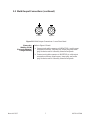
2.3 Weld Oouput Connections (continued)
Refer to Figure 2-B and:
a. Connect torch cable connector to NEGATIVE (-) weld output
receptacle as follows: align keyway, insert plug, and rotate
plug clockwise until it is securely seated in receptacle.
b. Connect work cable connector to POSITIVE (+) weld output
receptacle as follows: align keyway, insert plug, and rotate
plug clockwise until it is securely seated in receptacle.
Plasma Arc
Welding (PAW)
Electrode Negative/
Straight Polarity
Figure 2-B Weld Output Connections - Lower Front Panel
Positive Negative

INSTALLATION 8 Manual 0-2337
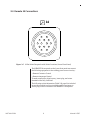
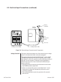
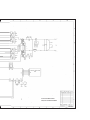
2.4 Remote 14 Connections
The REMOTE 14 receptacle on the lower front panel can connect
the following equipment to the welding power source circuitry:
• Remote Contactor Control
• Remote Amperage Control
To make connections, align keyway, insert plug, and rotate
threaded collar fully clockwise.
The following socket information (Table 2-B, page 9) is included
in case the supplied cord is not suitable, and it is necessary to
wire a plug or cord to interface with REMOTE 14 receptacle.
Figure 2-C 14-Pin Socket Receptacle with Socket Locations (Lower Front Panel)
14
A
B
C
D
E
J
I
L
K
NH
MG
F
La page est en cours de chargement...
La page est en cours de chargement...
La page est en cours de chargement...
La page est en cours de chargement...
La page est en cours de chargement...
La page est en cours de chargement...
La page est en cours de chargement...
La page est en cours de chargement...
La page est en cours de chargement...
La page est en cours de chargement...
La page est en cours de chargement...
La page est en cours de chargement...
La page est en cours de chargement...
La page est en cours de chargement...
La page est en cours de chargement...
La page est en cours de chargement...
La page est en cours de chargement...
La page est en cours de chargement...
La page est en cours de chargement...
La page est en cours de chargement...
La page est en cours de chargement...
La page est en cours de chargement...
-
 1
1
-
 2
2
-
 3
3
-
 4
4
-
 5
5
-
 6
6
-
 7
7
-
 8
8
-
 9
9
-
 10
10
-
 11
11
-
 12
12
-
 13
13
-
 14
14
-
 15
15
-
 16
16
-
 17
17
-
 18
18
-
 19
19
-
 20
20
-
 21
21
-
 22
22
-
 23
23
-
 24
24
-
 25
25
-
 26
26
-
 27
27
-
 28
28
-
 29
29
-
 30
30
-
 31
31
-
 32
32
-
 33
33
-
 34
34
-
 35
35
-
 36
36
-
 37
37
-
 38
38
-
 39
39
-
 40
40
-
 41
41
-
 42
42


ESAB Inverter Arc Welder Model PS-3000 Manuel utilisateur
- Catégorie
- Système de soudage
- Taper
- Manuel utilisateur
dans d''autres langues
Documents connexes
-
ESAB DRAG-GUN™ Plasma Cutter with Built-In Air Manuel utilisateur
-
 Thermal Arc FABRICATOR WELDER Manuel utilisateur
-
 Thermal Dynamics Plasma Welding Torch Model PWH/M-2A Manuel utilisateur
-
 Thermal Arc Inverter Arc Welder Model 400GTS CC/Tig Manuel utilisateur
-
 Thermal Dynamics 38 CUTMASTER™ Plasma Cutting System Manuel utilisateur
-
 Thermal Arc Inverter Arc Welder Model 400GMS CC/CV Manuel utilisateur
-
 Thermal Arc Inverter Arc Welder Model 130 GTS & S CC/TIG Manuel utilisateur
-
 Thermal Arc Inverter Arc Welder Model 150 GTS & S CC/TIG Manuel utilisateur
-
 Thermal Arc Inverter Arc Welder Model 400S Manuel utilisateur
-
 Thermal Arc Inverter Arc Welder Model LM300 CC/CV Manuel utilisateur


