Kichler Lighting 44380BK Manuel utilisateur
- Taper
- Manuel utilisateur

IS-44380-US
We’re here to help 866-558-5706
Hrs: M-F 9am to 5pm EST
2) Pass xture wire through end of swivel[C] without
threaded pipe. Thread that end of swivel onto end of last
stem. Note direcon of swivel in accordance with ceiling.
3) Pass xture wire through hole in canopy[D]. Pass
threaded pipe on end of swivel up through hole in
canopy.
4) Pass xture wire through lockwasher[E] . Thread
lockwasher onto end of threaded pipe protruding from
inside canopy.
5) Pass xture wire through hexnut[F]. Thread hexnut onto
end of threaded pipe.
6) Find the appropriate threaded holes on mounng
strap[G]. Assemble mounng screws[H] into threaded
holes.
7) Aach mounng strap to outlet box[I] using the strap
mounng screws[P]. Mounng strap can be adjusted to
suit posion of xture.
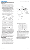
8) Grounding instrucons: (See Illus. a or b).
a) On xtures where mounng strap is provided with a
hole and two raised dimples, wrap ground wire from
outlet box around green ground screw, and thread
into hole.
b) On xtures where a cupped washer is provided,
aach ground wire from outlet box under cupped
washer and green ground screw, then thread into
mounng strap.
If xture is provided with ground wire, connect xture
ground wire to outlet box ground wire with wire
connector aer following the above steps. Never connect
ground wire to black or white power supply wires.
9) Make wire connecon. Reference chart below for correct
connecons and wire accordingly.
Connect Black or Red
Supply Wire to:
Connect White Supply
Wire to:
Black White
*Parallel cord (round &
smooth)
*Parallel cord (square &
ridged)
Clear, Brown, Gold or
Black without Tracer
Clear, Brown, Gold or Black
with Tracer
Insulated wire (other
than green) with copper
conductor
Insulated wire (other
than green) with silver
conductor
*Note: When parallel wire (SPT
1 & SPT 2) are used. The neutral
wire is square shaped or ridged
and the other wire will be round
in shape or smooth (See illus.)
Neutral Wire
10) Push xture to ceiling, carefully passing mounng screws
through holes in canopy. NOTE: Be certain wires do not
get pinched between canopy and ceiling.
11) Use knobs[J] and lockwashers[K] to secure canopy.
Tighten to secure.
12) Carefully raise glass[L] to the xture. Slip the smaller
opening over the socket[M] and t the glass against the
socket.
13) Thread socket ring[N] onto socket. Tighten socket ring to
secure glass in place. (DO NOT over ghten.)
14) Insert recommended bulb (Not supplied).
GREEN GROUND
SCREW
CUPPED
WASHER
OUTLET BOX
GROUND
FIXTURE
GROUND
DIMPLES
WIRE CONNECTOR
OUTLET BOX
GROUND
GREEN GROUND
SCREW
FIXTURE
GROUND
a
b
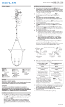
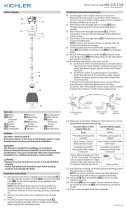
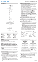
Fixture Diagram
Parts List
[A] Stems
[B] Short
Threaded
Tubes
[C] Swivel
[D] Canopy
[E] Lockwasher
[F] Hexnut
[G] Mounting
Strap
[H] Mounting
Screws
[I] Outlet Box
[J] Knobs
[K] Lockwashers
[L] Glass
[M] Socket
[N] Socket Ring
[O] Fixture body
[P] Strap
Mounting
Screws
Cauons
CAUTION – RISK OF SHOCK –
Disconnect Power at the main circuit breaker panel or main
fusebox before starng and during the installaon.
WARNING:
This xture is intended for installaon in accordance
with the Naonal Electrical Code (NEC) and all local code
specicaons. If you are not familiar with code requirements,
installaon by a cered electrician is recommended.
Installaon Instrucons
1) Pass xture wire through desired amount of stems[A]
and screw stems together using supplied short threaded
tubes[B]. Thread the assembled stems into the top of
the xture body[O].
NOTE: Thread locking compound must be applied to
all stem threads as noted with (4) symbol to prevent
accidental rotaon of xture during cleaning, relamping,
etc.
Installaon Instrucons (connued)
I
G
D
H
K
J
P
►
A
►
B
►►
►►
►
C
E
F
L
N
O
M

IS-44380-US
Estamos aquí para ayudarle 866-558-5706
Horario: Lunes-Viernes 9am a 5pm EST (hora ocial del este)
2) Pase el cable del artefacto a través del extremo de la unión
giratoria[C] sin tubo roscado. Enrosque ese extremo de la
unión giratoria al extremo del úlmo vástago. Tenga en cuenta
la dirección de la unión giratoria de acuerdo con el techo.
3) Pase el cable del artefacto a través del oricio en el
escudete[D]. Pase el tubo roscado en el extremo de la unión
giratoria hacia arriba a través del oricio en el escudete.
4) Pase el cable del artefacto a través de la arandela de
seguridad[E]. Enrosque la arandela de seguridad en el
extremo del tubo roscado que sobresale desde el interior del
escudete.
5) Pase el cable del artefacto a través de la tuerca hexagonal[F].
Enrosque la tuerca hexagonal en el extremo del tubo roscado.
6) Encuentre los oricios roscados apropiados en la abrazadera
de montaje[G]. Ensamble los tornillos de montaje[H] en los
oricios roscados.
7) Fije la abrazadera de montaje a la caja de distribución[I]
usando los tornillos de montaje de la abrazadera[P]. La
abrazadera de montaje se puede ajustar a la posición del
artefacto.
8) Instrucciones de conexión a erra solamente para los
Estados Unidos. (Vea la ilustracion a o b).
a) En las lámparas que enen el eje, de montaje con un
agujero y dos hoyuelos realzados, enrollar el alambre a
erra de la caja tomacorriente alrededor del tornillo verde
y pasarlo por el aquiero.
b) En las lámparas con una arandela acopada, jar el alambre
a erra de la caja tomacorriente del ajo de la arandela
acoada y tornillo verde, y paser por el eje de montaje.
Si la lámpara viene con alambre a erra, conecter el alambre a
erra de la lámpara al alambre a erra de la caja
tomacorriente con un conector de alambres espués de seguir
los pasos anteriores. Nunca conectar el alambra a erra a los
alambres eléctros negro o blanco.
9) Haga les conexiones de los alambres. La tabla de referencia
de abajo indica las conexiones correctas y los alambres
correspondientes.
Conectar el alambre de
suministro negro o rojo al
Conectar el alambre de
suministro blanco al
Negro Blanco
*Cordon paralelo (redondo
y liso)
*Cordon paralelo (cuadrado
y estriado)
Claro, marrón, amarillio
o negro sin hebra
idencadora
Claro, marrón, amarillio
o negro con hebra
idencadora
Alambre aislado (diferente
del verde) con conductor
de cobre
Alambre aislado (diferente
del verde) con conductor
de plata
*Nota: Cuando se uliza alambre
paralelo (SPT 1 y SPT 2). El alambre
neutro es de forma cuadrada o
estriada y el otro alambre será
de forma redonda o lisa. (Vea la
ilustracíón).
Hilo Neutral
10) Empuje el artefacto al techo, pasando cuidadosamente los
tornillos de montaje a través de los oricios en el escudete.
NOTA: Asegúrese de que ciertos cables no queden apretados
entre el escudete y el techo.
11) Use perillas[J] y arandelas de seguridad[K] para asegurar el
escudete. Ajuste para asegurar.
12) Suba cuidadosamente el vidrio[L] al artefacto. Deslice la
abertura más pequeña sobre el portalámparas[M] y ajuste el
vidrio contra éste.
13) Enrosque el anillo del portalámparas[N] en éste. Ajuste el
anillo del portalámparas para asegurar el vidrio en su lugar.
(NO ajuste demasiado)
14) Inserte las bombillas recomendadas (No se proveen).
ARANDELA
CONCAVA
TIERRA DE LA
CAJA DE SALIDA
TORNILLO DE TIERRA,
VERDE
DEPRESIONES
TIERRA
ARTEFACTO
CONECTOR DE ALAMBRE
TIERRA DE LA
CAJA DE SALIDA
TORNILLO DE TIERRA,
VERDE
TIERRA
ARTEFACTO
a
b
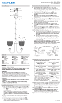
Diagrama de Accesorios
Lista de Partes
Precauciones
PRECAUCIÓN – RIESGO DE DESCARGA ELÉCTRICA –
Desconecte la electricidad en el panel principal del
interruptor automáco o caja principal de fusibles antes de
comenzar y durante la instalación.
ADVERTENCIA:
Este accesorio está desnado a la instalación de
acuerdo con el Naonal Electrical Code (NEC) y todas las
especicaciones del código local. Si no está familiarizado
con los requisitos del código, la instalación se recomienda
un electricista cercado.
Instrucciones de Instalación
1) Pase el cable del artefacto a través de la candad deseada
de vástagos[A] y enrósquelos usando los tubos roscados
cortos[B] suministrados. Enrosque los vástagos ensamblados
en la parte superior del cuerpo del artefacto[O].
NOTA: El compuesto para rosca estanca debe aplicarse a todas
las roscas del vástago como se indica con el símbolo (4) para
evitar la rotación accidental del artefacto durante la limpieza,
el cambio de lámparas, etc.
Instrucciones de instalación (connuación)
I
G
D
H
K
J
P
►
A
►
B
►►
►►
►
C
E
F
L
N
O
M
[A] Vástagos
[B] Tubos
Roscados
Cortos
[C] Giratoria
[D] Escudete
[E] Arandela de
Seguridad
[F] Tuerca
Hexagonal
[G] Abrazadera
de Montaje
[H] Tornillos de
Montaje
[I] Caja de
Distribución
[J] Perillas
[K] Arandelas de
Seguridad
[L] Vidrio
[M] Portalámparas
[N] Anillo del
Portalámparas
[O] Cuerpo del
Artefacto
[P] Tornillos de
Montaje de la
Abrazadera

IS-44380-CB
We’re here to help 866-558-5706
Hrs: M-F 9am to 5pm EST
2) Pass xture wire through end of swivel[C] without
threaded pipe. Thread that end of swivel onto end of last
stem. Note direcon of swivel in accordance with ceiling.
3) Pass xture wire through hole in canopy[D]. Pass
threaded pipe on end of swivel up through hole in
canopy.
4) Pass xture wire through lockwasher[E] . Thread
lockwasher onto end of threaded pipe protruding from
inside canopy.
5) Pass xture wire through hexnut[F]. Thread hexnut onto
end of threaded pipe.
6) Find the appropriate threaded holes on mounng
strap[G]. Assemble mounng screws[H] into threaded
holes.
7) Aach mounng strap to outlet box[I] using the strap
mounng screws[P]. Mounng strap can be adjusted to
suit posion of xture.
8) Grounding instrucons: (See Illus. a or b).
a) On xtures where mounng strap is provided with a
hole and two raised dimples, wrap ground wire from
outlet box around green ground screw, and thread
into hole.
b) On xtures where a cupped washer is provided,
aach ground wire from outlet box under cupped
washer and green ground screw, then thread into
mounng strap.
If xture is provided with ground wire, connect xture
ground wire to outlet box ground wire with wire
connector aer following the above steps. Never connect
ground wire to black or white power supply wires.
9) Make wire connecon. Reference chart below for correct
connecons and wire accordingly.
Connect Black or Red
Supply Wire to:
Connect White Supply
Wire to:
Black White
*Parallel cord (round &
smooth)
*Parallel cord (square &
ridged)
Clear, Brown, Gold or
Black without Tracer
Clear, Brown, Gold or Black
with Tracer
Insulated wire (other
than green) with copper
conductor
Insulated wire (other
than green) with silver
conductor
*Note: When parallel wire (SPT
1 & SPT 2) are used. The neutral
wire is square shaped or ridged
and the other wire will be round
in shape or smooth (See illus.)
Neutral Wire
10) Push xture to ceiling, carefully passing mounng screws
through holes in canopy. NOTE: Be certain wires do not
get pinched between canopy and ceiling.
11) Use knobs[J] and lockwashers[K] to secure canopy.
Tighten to secure.
12) Carefully raise glass[L] to the xture. Slip the smaller
opening over the socket[M] and t the glass against the
socket.
13) Thread socket ring[N] onto socket. Tighten socket ring to
secure glass in place. (DO NOT over ghten.)
14) Insert recommended bulb (Not supplied).
GREEN GROUND
SCREW
CUPPED
WASHER
OUTLET BOX
GROUND
FIXTURE
GROUND
DIMPLES
WIRE CONNECTOR
OUTLET BOX
GROUND
GREEN GROUND
SCREW
FIXTURE
GROUND
a
b
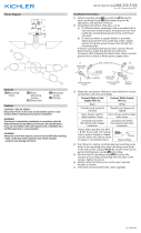
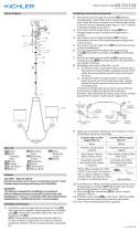
Fixture Diagram
Parts List
[A] Stems
[B] Short
Threaded
Tubes
[C] Swivel
[D] Canopy
[E] Lockwasher
[F] Hexnut
[G] Mounting
Strap
[H] Mounting
Screws
[I] Outlet Box
[J] Knobs
[K] Lockwashers
[L] Glass
[M] Socket
[N] Socket Ring
[O] Fixture body
[P] Strap
Mounting
Screws
Cauons
CAUTION – RISK OF SHOCK –
Disconnect Power at the main circuit breaker panel or main
fusebox before starng and during the installaon.
WARNING:
This xture is intended for installaon in accordance
with the Naonal Electrical Code (NEC) and all local code
specicaons. If you are not familiar with code requirements,
installaon by a cered electrician is recommended.
Installaon Instrucons
1) Pass xture wire through desired amount of stems[A]
and screw stems together using supplied short threaded
tubes[B]. Thread the assembled stems into the top of
the xture body[O].
NOTE: Thread locking compound must be applied to
all stem threads as noted with (4) symbol to prevent
accidental rotaon of xture during cleaning, relamping,
etc.
Installaon Instrucons (connued)
I
G
D
H
K
J
P
►
A
►
B
►►
►►
►
C
E
F
L
N
O
M

IS-44380-CB
Nous sommes là pour vous aider 866-558-5706
Heures : du lundi au vendredi, de 9h à 17h (heure de l’Est)
INSTRUCTIONS:
For Assembling and Installing Fixtures in Canada
Pour L’assemblage et L’installaon Au Canada
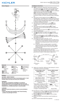
1) Passez le l du luminaire à travers le nombre de ges
souhaitées[A] et vissez les ges ensemble à l’aide
des tubes à lets courts (fournis)[B]. Vissez les ges
assemblées sur la pare supérieure du luminaire[O].
REMARQUE : Appliquer du frein let sur tous les lets
de la ge indiqués par le symbole (4) pour empêcher la
rotaon accidentelle du luminaire pendant le neoyage,
remplacement de lampe, etc.
2) Passez le l du luminaire par l’extrémité du pivot[C]
sans le tube leté. Vissez cee extrémité du pivot sur
l’extrémité de la dernière ge. Notez la direcon du pivot
en foncon du plafond.
3) Passez le l du luminaire par le trou situé dans le
cache[D]. Passez le tube leté sur l’extrémité du pivot
par le trou situé dans le cache.
4) Vissez le l du luminaire par la rondelle de blocage[E].
Vissez une rondelle de blocage sur l’extrémité du tube
leté sortant de l’intérieur du cache.
5) Passez le l du luminaire par l’écrou hexagonal[F]. Vissez
l’écrou hexagonal sur l’extrémité du tube leté.
6) Localisez les trous letés appropriés sur le support de
montage[G]. Vissez les vis de montage[H] dans les trous
letés.
7) Fixez le support de montage sur la boîte à prises[I] avec
les vis de xaon du support[P]. Le support de montage
peut être réglé en foncon de la posion du luminaire.
8) Connecter les ls. Se reporter au tableau ci-dessous pour
faire les connexions.
Connecter le l noir ou
rouge de la boite
Connecter le l blanc de
la boîte
A Noir A Blanc
*Au cordon parallèle (rond
et lisse)
*Au cordon parallèle (à
angles droits el strié)
Au transparent, doré,
marron, ou noir sans l
disncf
Au transparent, doré,
marron, ou noir avec un l
disncf
Fil isolé (sauf l vert) avec
conducteur en cuivre
Fil isolé (sauf l vert) avec
conducteur en argent
*Remarque: Avec emploi d’un
l paralléle (SPT 1 et SPT 2). Le
l neutre est á angles droits ou
strié et l’autre l doit étre rond
ou lisse (Voir le schéma).
Fil Neutre
9) Poussez le luminaire vers le plafond en passant
soigneusement les vis de montage par les trous dans
le cache. REMARQUE : Assurez-vous qu’aucun l n’est
coincé entre le cache et le plafond.
10) Ulisez les boutons[J] et les rondelles de blocage[K]
pour sécuriser le cache. Serrez pour xer.
11) Soulevez le verre[L] avec précauon jusqu’au luminaire.
Glissez la plus pete ouverture sur la douille[M] et placez
le verre contre la douille.
12) Vissez l’anneau de la douille[N] sur la douille. Serrez
l’anneau de douille pour xer le verre. (NE PAS serrer
avec excès).
13) Installez les ampoules recommandées (non fournies).
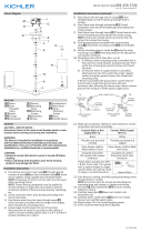
Diagramme d’appareils
ATTENTION – RISQUE DE DÉCHARGES ÉLECTRIQUES -
Couper le courant au niveau du panneau du disjoncteur du
circuit principal ou de la boîte à fusibles principale avant de
procéder à l’installaon.
ATTENTION:
Ce luminaire doit être installé conformément aux codes
d’électricité naonaux (NEC) et sasfaire toutes les
spécicaons des codes locaux. Si vous ne connaissez pas
les exigences de ces codes, il est recommandé de coner
l’installaon à un électricien ceré.
Liste des Pièces
Précauons
[A] Tiges
[B] Tubes à Filets
Courts
[C] Pivot
[D] Cache
[E] Rondelle de
Blocage
[F] L’écrou
Hexagonal
[G] Support de
Montage
[H] Vis de
Montage
[I] Boîte à Prises
[J] Boutons
[K] Rondelles de
Blocage
[L] Verre
[M] Douille
[N] L’anneau de la
Douille
[O] Luminaire
[P] Vis de
Fixation du
Support
Instrucons d’installaon
I
G
D
H
K
J
P
►
A
►
B
►►
►►
►
C
E
F
L
N
O
M
-
 1
1
-
 2
2
-
 3
3
-
 4
4


Kichler Lighting 44380BK Manuel utilisateur
- Taper
- Manuel utilisateur
dans d''autres langues
Documents connexes
-
 Kichler Lighting 43535CLP Manuel utilisateur
-
 Kichler Lighting 45892NI Manuel utilisateur
-
 Kichler Lighting 52164BK Manuel utilisateur
-
 Kichler Lighting 52314BNB Manuel utilisateur
-
 Kichler Lighting 52272BK Manuel utilisateur
-
 Kichler Lighting 43532CLP Manuel utilisateur
-
 Kichler Lighting 52269BK Manuel utilisateur
-
 Kichler Lighting 43531CLP Manuel utilisateur
-
 Kichler Lighting 52255BK Manuel utilisateur
-
 Kichler Lighting 52098BK Manuel utilisateur


