Yamaha RX V2095RDS Manuel utilisateur
- Catégorie
- Destinataire
- Taper
- Manuel utilisateur
Ce manuel convient également à

OWNER’S MANUAL
MODE D’EMPLOI
BEDIENUNGSANLEITUNG
BRUKSANVISNING
MANUALE DI ISTRUZIONI
MANUAL DE INSTRUCCIONES
GEBRUIKSAANWIJZING
OWNER’S MANUAL
MODE D’EMPLOI
BEDIENUNGSANLEITUNG
BRUKSANVISNING
MANUALE DI ISTRUZIONI
MANUAL DE INSTRUCCIONES
GEBRUIKSAANWIJZING
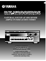
NATURAL SOUND AV RECEIVER
AMPLI-TUNER AUDIO-VIDEO
G
NATURAL SOUND AV RECEIVER RX V2095RDS
CINEMA DSP
7ch
VOLUME
INPUT SELECTOR
INPUT MODE
l6
20
28
40
60
l2
8
4
2
0
–dB
BASS TREBLE BALANCE
VCR 2
VIDEO AUX
REC OUT
VCR 1
TV/DBS
PHONO
TUNER
CD
DVD/LD
SOURCE
TAPE/MD
VIDEO AUX
EFFECT
A/B/C/D/E
PRESET STATIONS
TUNING
EXT. DECODER
55
4
3
2
l
0
l
2
3
4
LR
55
4
3
2
l
0
l
2
3
4
55
4
3
2
l
0
l
2
3
4
STANDBY/ON
PHONES
BASS
EXTENSION
TONE
BYPASS
A
SPEAKERS
B
PROGRAM
RDS MODE
EON
EDIT
FM/AM
MODE
MEMORY
START
PRESET
/TUNING
TUNING
MODE
PTY SEEK
MAN’L/AUTO FM AUTO/MAN’L MONO

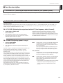
Congratulations!
You are the proud owner of a Yamaha Digital Sound Field Processing (DSP)
System—an extremely sophisticated audio component. The DSP system takes full
advantage of Yamaha’s undisputed leadership in the field of digital audio processing
to bring you a whole new world of listening experiences. Follow the instructions in this
manual carefully when setting up your system, and the DSP system will sonically
transform your room into a wide range of listening environments—anything from a
famous concert hall to a cozy jazz club. In addition, you get incredible realism from
most of surround-sound encoded video sources available in the market using the built-
in Dolby Pro Logic Surround Decoder, Dolby Digital Decoder and DTS Decoder.
Seven built-in channels of amplification on this model mean that no additional
amplifiers are required to enjoy advanced digital sound field processing.
Rather than tell you about the wonders of digital sound field processing, however,
let’s get right down to the business of setting up the system and trying out its many
capabilities. Please read this operation manual carefully and store it in a safe place for
later reference.

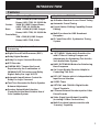
1
English
CAUTION .................................................................. 2
INTRODUCTION ....................................................... 3
Features .................................................................... 3
What’s DSP?............................................................. 4
GETTING STARTED ................................................ 7
Getting started.......................................................... 7
Unpacking.............................................................. 7
Opening and closing the front cover ...................... 7
Installing batteries in the remote controller ........... 8
Notes about the remote controller.......................... 8
Controls and their functions................................... 9
Front panel............................................................. 9
Display panel........................................................ 12
PREPARATION ...................................................... 13
Speaker setup......................................................... 13
Connections ........................................................... 15
Audio/video source equipment ............................ 15
Speakers ............................................................. 21
Antennas ............................................................. 24
Plugging in this unit ............................................. 26
On screen display.................................................. 27
Selecting the output modes
(“SET MENU” mode) ............................................. 28
Speaker balance adjustment ................................ 31
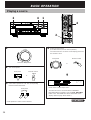
BASIC OPERATION ............................................... 34
Playing a source .................................................... 34
Recording a source to tape (or MD) or dubbing
from tape (or MD) to tape (or MD)......................... 39
Sound control......................................................... 41
Tuning ..................................................................... 42
Basic operation ................................................... 42
Preset tuning........................................................ 43
Receiving RDS stations .........................................47
Displaying RDS data.............................................47
Selecting your desired program type from among
preset RDS stations (PTY SEEK).........................50
Automatic selection of desired program when
broadcasting starts................................................51
Using digital sound field processor (DSP) ......... 52
Playing a source with an effect of the digital
sound field processor (DSP)................................ 52
Adjusting output level of the center, right rear,
left rear, front effect speakers and subwoofer...... 55
Brief overview of digital sound field programs...... 57
ADVANCED FEATURES ....................................... 62
SET MENU mode ................................................... 62
Creating your own sound fields .......................... 66
Setting the SLEEP timer ....................................... 71
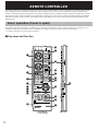
REMOTE CONTROLLER ....................................... 72
Basic operation (Cover is open) .......................... 72
Using the “learning-capable” keys
(Cover is open)....................................................... 74
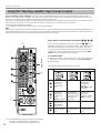
Using OPERATION CONTROL keys
(Cover is closed) ................................................... 76
Macro operations (Cover is closed) .................... 78
Methods of learning and clearing functions ....... 80
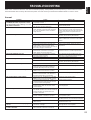
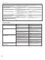
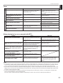
TROUBLESHOOTING ............................................ 83
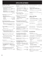
SPECIFICATIONS .................................................. 86
CONTENTS

2
1. To assure the finest performance, please read this manual
carefully. Keep it in a safe place for future reference.
2. Install this unit in a cool, dry, clean place – away from
windows, heat sources, sources of excessive vibration,
dust, moisture and cold. Avoid sources of humming
(transformers, motors). To prevent fire or electrical shock,
do not expose the unit to rain or water.
3. Never remove the unit cover. Contact your dealer if an
object falls inside the unit.
4. Do not use force on switches, controls or connection wires.
When moving the unit, first disconnect the power plug and
the wires connected to other equipment. Never pull on the
wires themselves.
5. The openings on the unit cover assure proper ventilation of
the unit. If these openings are obstructed, the temperature
inside the unit will rise rapidly. Therefore, avoid placing
objects against these openings, and install the unit in a
well-ventilated area to prevent fire and damage.
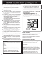
<Europe and U.K. models>
Be sure to allow a space of at least 10 cm behind, 20 cm
on the both sides and 30 cm above the top panel of the
unit to prevent fire and damage.
6. The voltage used must be the same as that specified on
this unit. Using this unit with a higher voltage than
specified is dangerous and may result in fire or other
accidents. YAMAHA will not be held responsible for any
damage resulting from use of this unit with a voltage other
than specified.
7. Digital signals generated by this unit may interfere with
other equipment such as tuners, receivers or TVs. Move
this unit farther away from such equipment if interference
is observed.
8. Always set the VOLUME control to “–
∞
” before starting
the audio source play. Increase the volume gradually to an
appropriate level after playback has been started.
9. Do not attempt to clean the unit with chemical solvents;
this might damage the finish. Use a clean, dry cloth.
10.Be sure to read the “TROUBLESHOOTING” section
regarding common operating errors before concluding that
the unit is faulty.
11.When not planning to use this unit for long periods of time,
disconnect the AC power plug from the wall outlet.
12.To prevent lightning damage, disconnect the AC power
plug and antenna cable when there is an electrical storm.
13.Grounding or polarization – Precautions should be taken
so that the grounding or polarization of an appliance is not
defeated.
14.Do not connect an audio unit to the AC outlet on the rear
panel if the equipment requires more power than the outlet
is rated to provide.
IMPORTANT
Please record the serial number of your unit in the space
below.
Model:
Serial No.:
The serial number is located on the rear of the unit.
Retain this Owner’s Manual in a safe place for future
reference.
WARNING
TO REDUCE THE RISK OF FIRE OR ELECTRIC
SHOCK, DO NOT EXPOSE THIS UNIT TO RAIN OR
MOISTURE.
This unit is not disconnected from the AC power source as
long as it is connected to the wall outlet, even if this unit
itself is turned off. This state is called the standby mode.
In this mode, this unit is designed to consume a small
amount of power.
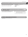
WARNING
Do not change the IMPEDANCE SELECTOR switch
setting while the power to this unit is on, otherwise this
unit may be damaged.
IF THIS UNIT FAILS TO TURN ON WHEN THE
STANDBY/ON SWITCH IS PRESSED;
The IMPEDANCE SELECTOR switch may not be set to
either end. If so, set the switch to either end when this unit
is in the standby mode.
For U.K. customers
If the socket outlets in the home are not suitable for the plug
supplied with this appliance, it should be cut off and an
appropriate 3 pin plug fitted. For details, refer to the
instructions described below.
Note: The plug severed from the mains lead must be
destroyed, as a plug with bared flexible cord is hazardous if
engaged in a live socket outlet.
Special Instructions for U.K. Model
IMPORTANT
THE WIRES IN MAINS LEAD ARE COLOURED IN
ACCORDANCE WITH THE FOLLOWING CODE:
Blue: NEUTRAL
Brown: LIVE
As the colours of the wires in the mains lead of this
apparatus may not correspond with the coloured markings
identifying the terminals in your plug, proceed as follows:
The wire which is coloured BLUE must be connected to the
terminal which is marked with the letter N or coloured
BLACK. The wire which is coloured BROWN must be
connected to the terminal which is marked with the letter L
or coloured RED. Making sure that neither core is
connected to the earth terminal of the three pin plug.
OR CORRECT SETTING.
KERS
A
B
REAR
AIN
SWITCHED
AC OUTLETS
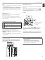
IMPEDANCE SELECTOR
CENTER : 4
Ω
MIN. / SPEAKER
FRONT
:6
Ω
MIN. / SPEAKER
REAR
:6
Ω
MIN. / SPEAKER
MAIN A OR B
:4
Ω
MIN. / SPEAKER
A B
:8
Ω
MIN. / SPEAKER
CENTER : 8
Ω
MIN. / SPEAKER
FRONT
:8
Ω
MIN. / SPEAKER
REAR
:8
Ω
MIN. / SPEAKER
MAIN A OR B
:8
Ω
MIN. / SPEAKER
A B
:
I
6
Ω
MIN. / SPEAKER
( SURROUND )
SET BEFORE POWER ON
I00W MAX.
TOTAL
IMPEDANCE
SELECTOR
(Europe model)
CAUTION : Read this before operating your unit.

3
English
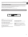
7 Channel Power Amplification
Main: 100W + 100W (8Ω) RMS Output
Power, 0.02% THD, 20–20,000 Hz
Center: 100W (8Ω) RMS Output Power,
0.02% THD, 20–20,000 Hz
Rear: 100W + 100W (8Ω) RMS Output
Power, 0.02% THD, 20–20,000 Hz
Front effect:
25W + 25W (8Ω) RMS Output
Power, 0.05% THD, 1 kHz
Multi-Mode Digital Sound Field
Processing
●
Digital Sound Field Processor (DSP)
●
Dolby Digital Decoder
●
Dolby Pro Logic Surround Decoder
●
DTS Decoder
●
CINEMA DSP: Theater-like Sound
Experience by the Combination of
YAMAHA DSP Technology and Dolby
Digital, Dolby Pro Logic or DTS
●
Automatic Input Balance Control for
Dolby Pro Logic Surround
●
Test Tone Generator for Easier Speaker
Balance Adjustment
●
Speaker Output Mode Selection
Capability for the Most Suitable Use of
Your Speaker System
Sophisticated FM/AM Tuner
● 40-Station Random Access Preset Tuning
● Automatic Preset Tuning
● Preset Station Shifting Capability (Preset
Editing)
● Multi-Functions for RDS Broadcast
Reception
● IF Count Direct PLL Synthesizer Tuning
System
Others
●
“SET MENU” Mode which Provides You
with 8 Titles of Setting Changes and
Adjustments for Optimizing This Unit for
Your Audio/Video System
● BASS EXTENSION Button for Reinforcing
Bass Response
● On Screen Display Function Helpful in
Controlling This Unit
●
REC OUT Selector which is Independent of
Input Source Selection
● SLEEP Timer
●
OPTICAL and COAXIAL Digital Audio
Signal Terminals
●
6 Channel External Decoder Input for Other
Future Formats
● Video Signal Input/Output Capability
(Including S Video Connections)
●
Multi-Functional
remote controller
with
“Learning” Capability
Features
INTRODUCTION

4
Welcome to the exciting world of digital home entertainment.
This unit is one of the most complete and advanced AV
receiver available. Some of the more advanced features may
not be familiar to you, but they are easy to use. State-of-the-art
technologies such as Dolby Digital and Digital Theater
Systems (DTS) may be new to your home, but you have
probably experienced the amazing realism they bring to feature
films in theaters around the world.
To make the listening experience even more enjoyable, this
unit includes a number of exclusive, digitally created listening
environments known as digital sound fields. Choosing a sound
field program is like transporting yourself to such venues as an
outdoor arena, a European church, or a cozy jazz club. Take
some time now to read more about these features and enjoy
the new experiences this unit brings to your home theater.
Digital Sound Field Processing
Technological advances in sound reproduction over the last 30
years have enhanced the listening experience with improved
clarity, precision and power. However, something has still been
missing: The atmosphere and acoustic ambiance of the public
venue. Our Yamaha engineers have extensively researched
the nature of sound acoustics and the way sound reflects
inside a room. We sent these engineers to famous theaters
and concert halls around the world to measure the acoustics of
those venues with sophisticated microphones. The data they
collected is used to recreate these environments in digital
sound fields. Some of these digital sound fields are created
using data measured directly at the original venue; others are
created from combinations of data to form unique
environments for specific purposes.
Of course, that only solves half of the problem. These
engineers have no way of knowing the acoustics of your
listening room, so we’ve made it possible for you to adjust the
various parameters of this data to tailor each virtual venue to
your taste. You can use these sound fields to enhance any
source and in combination with any of the following surround
sound technologies. Some are designed especially for music,
and some especially for movies.
Dolby Pro Logic Surround
Dolby Surround has been used in movie theaters since the
mid-seventies. It has also been available in home
entertainment systems since the late eighties and continues to
be a popular format for home theater systems. It uses four
discrete channels and five speakers to reproduce realistic and
dynamic sound effects: two main channels (left and right), a
center channel for dialog, and a rear channel for special sound
effects. The rear channel reproduces sound within a narrow
frequency range.
Most video tapes and laser discs include Dolby Surround
encoding as do many TV and cable broadcasts. The Dolby Pro
Logic Surround decoder built into this unit employs a digital
signal processing system that stabilizes each channel for even
more accurate sound positioning than is available with
standard analog processors.
Introduction
What’s DSP?
INTRODUCTION

5
English
Dolby Digital is the next level of Dolby Surround sound system
developed for 35 mm film-movies by employing low bit-rate
audio coding.
Dolby Digital is a digital surround sound system that provides
completely independent multi-channel audio to you. Dolby
Digital provides five full range channels in what is sometimes
referred to as a “3/2” configuration: three front channels (left,
center and right), and two surround channels. A sixth bass-only
effect channel is also provided for output of LFE (low frequency
effect), or low bass effects that are independent of other
channels. (This is called the “LFE channel”.) This channel is
counted as 0.1, thus giving rise to the term 5.1 channels in
total.
Compared to Dolby Pro Logic that is referred to a “3/1” system
(left front, center, right front and just one surround channel),
Dolby Digital features two surround channels, called stereo or
split surrounds, each offering the same full range fidelity as the
three front channels.
By using the built-in Dolby Digital decoder, you can experience
the dramatic realism and impact of Dolby Digital theater sound
in your home.
Wide dynamic range of sound reproduced by the five full range
channels and precise sound orientation by the digital sound
processing presents listeners much excitement and realism
that has never been experienced before.
Dolby Digital forms 5.1 channels as mentioned left, and
moreover, it can also form fewer channels, for example 2
channel stereo and monaural. You may be able to find some 2
channel stereo and/or monaural sources encoded with Dolby
Digital in the market.
Laserdisc and DVD are home audio formats that could benefit
from Dolby Digital. In the near future, Dolby Digital will also be
applied to DBS, CATV and HDTV. The ongoing release of
Dolby Stereo Digital theatrical films now underway will provide
an immediate source of Dolby Digital encoded video software.
Manufactured under license from Dolby Laboratories. “Dolby”,
“AC-3”, “Pro Logic”, and the double-D symbol are trademarks
of Dolby Laboratories.
DTS (Digital Theater Systems) system was developed to
replace analog soundtracks of movies with six discrete
channels of digital soundtracks, and now, it is installed in many
theaters around the world. The DTS digital playback system
changed the way we experienced movies in theaters with six
discrete channels of superb digital audio.
The DTS technology, through intense research and
development, made it possible to deliver a similar
encode/decode discrete technology to home audio surround-
sound entertainment.
The DTS Digital Surround is an encode/decode system which
delivers six channels of master-quality, 20-bit audio; technically
5.1 channels, which means 5 full-range (left, center, right and
two surround) channels, plus a subwoofer (LFE) channel (as
“0.1”). It is compatible with the 5.1 speaker configurations that
are currently available for home theater systems
The DTS Digital Surround algorithm is designed to encode the
six channels of 20-bit audio onto some laserdiscs, compact
discs and DVDs with considerably less data-compression.
By using the DTS decoder built into this unit, you can
experience the dramatic realism and impact of the DTS
installed theater’s high quality sound in your home.
Laserdisc, compact disc and DVD are home audio format
within which DTS can represent its high quality multi-channel
audio. (In addition to movies on laserdiscs, many exciting new
multi-channel music recordings will also become available in
the form of DTS-encoded compact discs.)
Manufactured under license from Digital Theater Systems, Inc.
US Pat. No. 5,451,942 and other world-wide patents issued
and pending. “DTS”, “DTS Digital Surround”, are trademarks of
Digital Theater Systems, Inc. Copyright 1996 Digital Theater
Systems, Inc. All Rights Reserved.
DTS Digital Surround
Dolby Digital
INTRODUCTION

6
Dolby Pro Logic + 2 Digital Sound Fields
Digital sound fields are created on the presence side and
the rear surround side of the Dolby Pro Logic Surround-
decoded sound field respectively. They create a wide
acoustic environment and emphasize surround-effect in the
room, letting you feel much presence as if you were
watching a movie in a popular Dolby Surround theater.
This combination is available when the digital sound field
program No. 8, 9, 10, 11 or “PRO LOGIC/Enhanced” of No.
12 is selected, and the input signal of the source is analog,
PCM audio or encoded with the Dolby Digital in 2-channels.
Dolby Digital or DTS + 3 Digital Sound Fields
Digital sound fields are created on the presence side and
the independent left and right surround sides of the Dolby
Digital-decoded or the DTS-decoded sound field
respectively. They create a wide acoustic environment and
much surround effect in the room without losing high
channel separation. With wide dynamic range of Dolby
Digital or DTS sound, this sound field combination lets you
feel as if you were watching a movie in the newest Dolby
Digital theater or DTS installed theater. This is the most
ideal home theater sound at the present time.
This combination is available when the digital sound field
program No. 8, 9, 10, 11 or “DOLBY DIGITAL (or DTS
DIGITAL SUR.)/Enhanced” of No. 12 is selected, and the
input signal of the source is encoded with the Dolby Digital
(except in 2-channels) or encoded with the DTS.
CINEMA DSP: Dolby Surround + DSP / DTS + DSP
The Dolby Surround sound and DTS systems show their full
ability in a large movie theater, because movie sounds are
originally designed to be reproduced in a large movie theater
that uses a multitude of speakers. Trying to create a sound
environment similar to that of a movie theater in your home is
difficult because of the room size, material inside the walls, the
number of speakers, and so on. In other words, your listening
room is very different from a movie theater.
However, Yamaha DSP technology allows you to create nearly
the same sound experience as that of a large movie theater in
your home by compensating for the lack of presence and
dynamics in the listening room with original digital sound fields
combined with Dolby Surround or DTS Digital Surround
sounds.
The YAMAHA “CINEMA DSP” logo indicates those programs
that are created by the combination of YAMAHA DSP
technology and Dolby Surround or DTS.
CINEMA DSP
INTRODUCTION

7
English
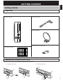
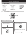
GETTING STARTED
Getting started
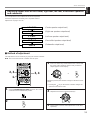
Remote controller
User function stickers
Indoor FM Antenna
AM Loop Antenna
Batteries (size AA, LR6, UM-3)
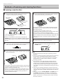
Unpacking
Carefully remove this unit and accessories from the box. You should find the unit itself and the following accessories.
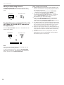
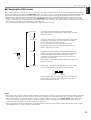
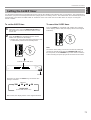
Close the front cover whenever the controls inside the panel are not used.
To open the front cover
Opening and closing the front cover
To close the front cover

8
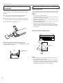
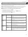
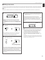
Installing batteries in the remote
controller
Since the remote controller will be used for many of this unit’s
control operations, you should begin by installing the supplied
batteries.
1. Turn the remote controller over and slide the battery
compartment cover in the direction of the arrow.
2. Insert the batteries (AA, LR6, UM-3 type) according to the
polarity markings on the inside of the battery compartment.
3. Close the battery compartment cover.
Note on the remote controller for the main room
After the batteries are inserted, press the RESET button before
using the remote controller.
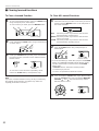
Notes about the remote controller
Battery replacement
If you find that the remote controller must be used closer to the
main unit, the batteries are weak. Replace both batteries with
new ones.
Notes
●
Use only AA, R6, UM-3 batteries.
(It is recommended to use an LR6 type to use the remote
controller for a long period of time.)
●
Be sure the polarities are correct. (See the illustration inside
the battery compartment.)
●
Remove the batteries if the remote controller is not used for
an extended period of time.
●
If batteries leak, dispose of them immediately. Avoid
touching the leaked material and contact with clothing, etc.
Clean the battery compartment thoroughly before installing
new batteries.
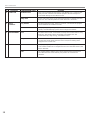
Remote controller operation range
Notes
●
The area between the remote controller and the main unit
must be clear of large obstacles.
●
Do not expose the remote control sensor to strong lighting,
in particular, an inverter type fluorescent lamp. Otherwise,
the remote controller may not work properly. If necessary,
position the main unit away from direct lighting.
1
3
2
RESET button
30°
30°
Remote control
sensor
Within approximately
6 m (19.7 feet)
GETTING STARTED

9
English
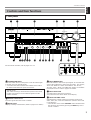
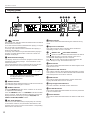
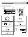
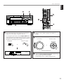
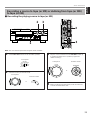
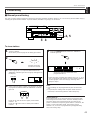
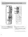
Controls and their functions
Front panel
NATURAL SOUND AV RECEIVER RX V2095RDS
CINEMA DSP
7ch
VOLUME
INPUT SELECTOR
INPUT MODE
l6
20
28
40
60
l2
8
4
2
0
–dB
PHONES
BASS
EXTENSION
BASS TREBLE BALANCE
TONE
BYPASS
VCR 2
VIDEO AUX
REC OUT
VCR 1
TV/DBS
PHONO
TUNER
CD
DVD/LD
SOURCE
TAPE/MD
VIDEO AUX
EFFECT
A/B/C/D/EA
SPEAKERS
B
PROGRAM
PRESET STATIONS
TUNING
EXT. DECODER
STANDBY/ON
55
4
3
2
l
0
l
2
3
4
LR
55
4
3
2
l
0
l
2
3
4
55
4
3
2
l
0
l
2
3
4
B
1
E G ICJ
23 4
5
6
87 0 A9 D FH
RDS MODE
EON
EDIT
FM/AM
MODE
MEMORY
START
PRESET
/TUNING
TUNING
MODE
PTY SEEK
MAN’L/AUTO FM AUTO/MAN’L MONO
RDS MODE
EON
EDIT
FM/AM
MODE
MEMORY
START
PRESET
/TUNING
TUNING
MODE
PTY SEEK
MAN’L/AUTO FM AUTO/MAN’L MONO
O
K
L M N
PQR
1 STANDBY/ON switch
Press this switch to turn on the power. Press this switch again
to set this unit in the standby mode.
* A click from the switch and the initial rotation of the built-in
fan will be heard when the power is turned on.
Standby mode
This unit is still using a small amount of power in this mode
in order to be ready to receive infrared-signals from the
remote controller.
2 Remote control sensor
Receives signals from the remote controller.
3 Display panel
Displays a variety of information. (Refer to page 12 for details.)
4 INPUT MODE button
Press this button to select how input signals are received from
sources that output two or more types of signals. The “AUTO”,
“DTS” and “ANALOG” modes are available. The “AUTO”,
“D.D.RF”, “DTS”, “DGTL” and “ANALOG” modes are available
for DVD/LD sources. Refer to page 37 for details.
5 INPUT SELECTOR
Turn this knob to select the input source.
The selected source will be shown on the display.
6 Master VOLUME control
Simultaneously controls volume for all output sounds; front
effect, main, rear, center and subwoofer. (The REC OUT level
is not affected.)
* The indicator on the master VOLUME control will flash when
the volume is decreased by pressing the MUTE key on the
remote controller.
For the remote controller, refer to pages 72 to 73.
GETTING STARTED

10
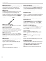
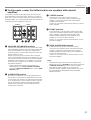
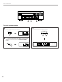
7
SPEAKERS switches
Press the switch A or B (or both) for the main speakers you will
use to select them. Press the switch for the main speakers you
will not use again to cancel them. On the display panel,
“SPEAKERS A” and/or “SPEAKERS B” will be illuminated,
depending on which main speakers are being selected.
8 PHONES jack
Headphones can be plugged into this jack for private listening.
You can listen to the sound to be output from the main
speakers through headphones. When listening with
headphones privately, press both SPEAKERS A and B
switches to cancel both of the main speakers A and B, and turn
off the digital sound field processor by pressing the EFFECT
button so that no DSP program name is illuminated on the
display panel.
9 PROGRAM selector button
Press this button in the or direction to select a digital
sound field processing program.
0 BASS EXTENSION button
Press this button inward (ON) to boost the bass frequency
response at the main left and right channels while maintaining
overall tonal balance. This function is effective for reinforcing
the bass frequencies when a subwoofer is not used.
A TONE BYPASS button
Press this button inward (ON) to bypass the tone (BASS and
TREBLE) control circuitry. This function is used for outputting
pure sound and checking the tone control settings. The tone
control circuitry can be used when this button is released
outward (OFF).
B EFFECT button
Press this button to turn on and off the output from the center,
rear and front effect speakers. The sound becomes normal 2-
channel when this function is turned off.
However, this does not apply to Dolby Digital or DTS. The
signals at all channels will be distributed to the main channels
and output from the main speakers, even if the output from the
center, rear and front effect speakers are turned off, when
Dolby Digital or DTS is decoded.
C BASS and TREBLE controls
Rotate these knobs to adjust the low and high frequency
response for the left and right main channels only.
D EXT. DECODER button
Press this button to select the input signals from the
EXTERNAL DECODER INPUT terminals as the input source.
This function takes priority over the INPUT SELECTOR setting.
“EXT. DECODER IN” will be illuminated on the display panel.
The source selected with the INPUT SELECTOR knob
becomes the current input source when “EXT. DECODER IN”
is not illuminated on the display panel.
E BALANCE control
This knob controls the sound from the main speakers only.
The balance of the output volume to the left and right main
speakers can be adjusted to compensate for sound imbalances
caused by the speaker location or listening room conditions.
F A/B/C/D/E button
Press this button to select a group (A–E) of preset stations.
G REC OUT selector
Rotate this knob to select the source for recording to an MD
recorder (or tape deck) or VCR. This setting is independent of
the INPUT SELECTOR setting, except when the REC OUT
selector is set to the SOURCE position. Then the INPUT
SELECTOR is used to select the source for recording to the
MD recorder (or tape deck) or VCR.
H PRESET STATIONS/TUNING button
This button is used for the PRESET STATIONS function when
“ : ” is illuminated on the display, and the TUNING function
when “ : ” is not illuminated. The following explains these
functions in detail.
PRESET STATIONS :
Selects a preset station number (from 1 to 8).
Press the side to select a higher preset station number.
Press the side to select a lower preset station number.
TUNING :
Used for tuning. Press the side to tune in to a higher
frequency, and press the side to tune in to a lower
frequency.
When this unit is in the PTY SEEK mode, pressing this button
changes the currently selected program type.
I VIDEO AUX terminals
Connect an auxiliary video or audio input source unit such as a
camcorder to these terminals. A video unit with a S video
output terminal can be connected to the S VIDEO terminal to
obtain a high resolution picture. The source can be selected
with the INPUT SELECTOR and REC OUT selector.
J Front cover
Refer to page 7 on how to open and close the front cover.
PHONES
GETTING STARTED

11
English
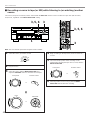
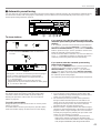
GETTING STARTED
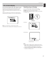
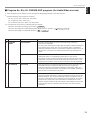
K RDS MODE button
When an RDS station is received, pressing this button changes
the display mode into the PS mode, PTY mode, RT mode
and/or CT mode (if the station employs these RDS data
services) in turn.
L EON button
Press this button to select a desired program type (NEWS,
INFO, AFFAIRS, SPORT) when you want to call a radio
program of that program type automatically.
M PTY SEEK MODE button
Press this button to set the unit to the PTY SEEK mode.
N PTY SEEK START button
Press this button to begin searching for a station after the
desired program type is selected in the PTY SEEK mode.
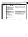
O PRESET/TUNING (EDIT) button
Press this button to alternately illuminate and turn off
“PRESET” on the display panel
. This button switches the
function of the PRESET STATIONS/TUNING button.
This button is also used to exchange the places of two preset
stations with each other.
P FM/AM button
Press this button to switch the reception band between FM and AM.
Q MEMORY (MAN’L/AUTO FM) button
Use this button to enter a station to memory. Refer to the
section “Manual preset tuning” on page 43 for details.
Hold down this button for more than 3 seconds to start
automatic preset tuning. Refer to page 45 for details.
R TUNING MODE (AUTO/MAN’L MONO) button
Press this button to switch the tuning mode between automatic
and manual. To select the automatic tuning mode, press this
button so that the “AUTO” indicator is illuminated on the
display. To select the manual tuning mode, press this button so
that the “AUTO” indicator is not illuminated.

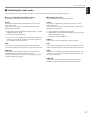
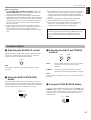
12
Display panel
DIGITAL
PRO LOGIC
DSP
SPEAKERS
AB
TAPE/MD
CD
TUNER
PHONO
DVD/LD
TV/DBS
VCR 1
VCR 2
V-AUX
MEMORY
PS PTY
RT CT
STEREO
AUTO
EON
PTY HOLD
NEWS
INFO
SPORT
AFFAIRS
SLEEP
2 74 5 631
980 BA CD
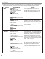
1 indicators
Either of the “dts” indicators will be illuminated when the built-in
DTS decoder is turned on.
A red “dts” indicator will be illuminated when playing a compact
disc or laserdisc encoded with DTS.
An orange “dts” indicator will be illuminated when playing a
DVD encoded with DTS.
An orange “dts” indicator may be illuminated when playing a
laserdisc encoded with DTS after a video-CD or DVD on a
DVD/LD combi-player.
2 Multi-information display
This display shows the current DSP program and the status of
adjustments and setting changes. Several statuses can be
viewed at one time.
The current station frequency and band (AM or FM) will also
appear when the tuner source input mode is selected.
3 STEREO indicator
This indicator will be illuminated when an FM stereo broadcast
with sufficient signal strength is received.
4 MEMORY indicator
A flashing MEMORY indicator means a station can be saved,
as explained in the following:
Press the MEMORY button. The MEMORY indicator will flash
about 5 seconds. While the indicator is flashing, program the
displayed station to memory by using the A/B/C/D/E and
PRESET STATIONS/TUNING buttons.
5 RDS mode indicators
The name(s) of the RDS mode(s) employed by the currently
received RDS station is (are) illuminated. Illumination of the
indicator on the head of a name shows that the corresponding
RDS mode is now selected.
6 AUTO indicator
This indicator will be illuminated during the automatic tuning
mode.
7 Input source indicators
One of the arrows for these indicators will be illuminated
depending on which source is selected.
8 DIGITAL and PRO LOGIC indicators
The DIGITAL indicator will be illuminated when the built-in
Dolby Digital decoder is on and the signals of the source
encoded with Dolby Digital are not 2-channels.
The PRO LOGIC indicator will be illuminated when the
built-in Dolby Pro Logic Surround Decoder is on.
9 DSP indicator
This indicator will be illuminated when the built-in digital sound
field processor is on.
0 SPEAKERS A/B indicators
One of these indicators will be illuminated depending on which
main speakers are selected. Both indicators will be illuminated
when both speakers A and B are selected.
A EON indicator
This indicator will be illuminated when an RDS station that
employs the EON data service is received.
B Program type name indicators
The name selected in the EON mode is illuminated.
C PTY HOLD indicator
This indicator will be illuminated while the search is performed
in the PTY SEEK mode.
D SLEEP indicator
This indicator will be illuminated when the built-in SLEEP timer
is on.
GETTING STARTED
SPEAKERS
A
TAPE/MD
CD
TUNER
PHONO
DVD/LD
TV/DBS
VCR 1
VCR 2
V-AUX
MEMORY
STEREO
AUTO
Indicates the signal level of the received station.
If multipath interference is detected, the
indication decreases.

13
English
This unit has been designed to provide the best sound field
quality with a full seven-speaker system setup, using a pair of
main speakers to output main source sounds, two extra pairs
of effect speakers to generate the sound field plus one center
speaker for dialog. We therefore recommend that you use a
seven-speaker setup. A four-speaker system using only one
pair of effect speakers for the sound field will still provide
impressive ambience and effects, however, and may be a
good way to begin with this unit. You can always upgrade to
the full seven-speaker system later. In the 4 or 5 speaker
system, the Digital Sound Field Processing is still performed,
but the main speakers are used for both the main channels
and the front effect channels.
Use of the center dialog speaker is
recommended
When playing back a source with Dolby Pro Logic decoded, or
playing back a source which contains center-channel signals
with Dolby Digital or DTS decoded, dialog, vocals etc. are
output from the center channel. Therefore, if you want to
maximize the performance of your Audio/Video home theater
system, it is recommended that you use a center channel
speaker.
If, for some reason, it is not practical to use a center speaker, it
is possible to enjoy the movie without it. Best results, however,
are obtained with the full system.
Use of a subwoofer expands your sound
field
It is also possible to further expand your system with the
addition of a subwoofer and amplifier. The use of a subwoofer
is effective not only for reinforcing bass frequencies from any
or all channels, but also for reproducing signals at the
subwoofer channel with high fidelity during playing back a
source with Dolby Digital or DTS decoded. You may wish to
choose the convenience of a Yamaha Active Servo Processing
Subwoofer System, which has its own built-in power amplifier.
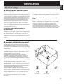
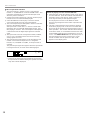
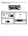
Speaker setup
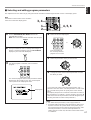
m Speakers and speaker placement
Your full seven-speaker system will require three speaker
pairs: the MAIN SPEAKERS (your normal stereo speakers),
the FRONT EFFECT SPEAKERS and the REAR SPEAKERS,
plus the CENTER SPEAKER. You may also be using a
SUBWOOFER.
The MAIN SPEAKERS should be high performance models
and have enough power handling capacity to accept the
maximum output of your audio system.
Other speakers do not have to be equal to the MAIN
SPEAKERS. For precise sound localization, however, it is
ideal to use high performance models that can reproduce
sounds in full range for the CENTER SPEAKER, the FRONT
EFFECT and REAR SPEAKERS.
Place the MAIN SPEAKERS in the ordinary position.
Place the FRONT EFFECT SPEAKERS further apart than the
MAIN SPEAKERS, on either side of and 0.5–1m behind and
above the MAIN SPEAKER pair.
Place the REAR SPEAKERS behind your listening position.
They should be nearly 1.8m above the floor.
Place the CENTER SPEAKER precisely between the two
MAIN SPEAKERS. (To avoid interference, keep the speaker
above or below the television monitor, or use a magnetically
shielded speaker.)
If using a SUBWOOFER, such as a Yamaha Active Servo
Processing Subwoofer System, the position of the speaker is
not so critical because low bass tones are not highly
directional.
m Setting up your speaker system
Main speaker
Front effect speaker
Center speaker
Rear speaker
Subwoofer
PREPARATION

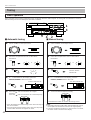
14
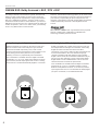
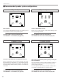
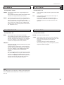
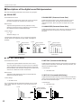
4 Speaker System
Basic system.
You can enjoy widely diffused sound by only adding a pair of
rear speakers to a basic stereo speaker system.
1E. SYS. SETUP—Set to 5ch. (See page 29.)
1A. CENTER SP—Set to NONE. (See page 28.)
6 Speaker System
Good for sound fields from 2-channel stereo sources.
When a normal stereo source is played back with the sound
field programs No. 1 through No. 7, a sound effect matching
that of a 7-speaker system can be obtained. The addition of
front left and right effect speakers produces a more effective
sound field.
1E. SYS. SETUP—Set to 7ch. (See page 29.)
1A. CENTER SP—Set to NONE. (See page 28.)
5 Speaker System
Good for Audio/Video sources.
By the use of a center speaker, center sounds (dialog, vocals
etc.) are precisely localized.
1E. SYS. SETUP—Set to 5ch. (See page 29.)
1A. CENTER SP—Set to LRG or SML. (See page 28.)
7 Speaker System
This is the recommended speaker system, providing the
best sound effects.
The rear speakers and the front effect speakers produces a
360-degree sound field, and the center speaker provides
precise center localization.
You can experience the amazing YAMAHA “CINEMA DSP”
sound fields completely with the 7 speaker system.
1E. SYS. SETUP—Set to 7ch. (See page 29.)
1A. CENTER SP—Set to LRG or SML. (See page 28.)
m Recommended speaker system configurations
PREPARATION

15
English
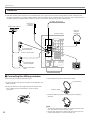
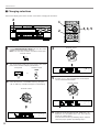
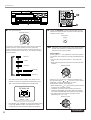
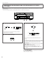
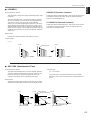
Caution: Plug in this unit and other components after all connections are completed.
All connections must be correct, that is to say L (left) to L, R (right) to R, “+” to “+” and “–” to “–”. Also refer to the owner’s manual for
each of your components.
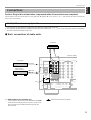
Audio/video source equipment
●
Use RCA type pin plug cables for audio/video units with the exception described later.
●
The output (or input) terminals of YAMAHA audio/video units numbered as 1, 3, 4, etc. on the rear panel must be connected to
the same-numbered terminals of this unit.
VIDEO
DVD/LD
TV/DBS
IN
VCR 1
OUT
IN
VCR 2
OUT
VIDEO
S VIDEO
DVD/LD
TV/DBS
IN
VCR 1
OUT
IN
VCR 2
OUT
MONITOR
OUT
S VIDEO
75Ω
UNBAL.
AM
ANT
FM
ANT
GND
AUDIO SIGNAL VIDEO SIGNAL
TV/DBSCD
CDDVD/LD
TAPE/MD
IN
(PLAY)
OUT
(REC)
DVD/LD
EXTERNAL
DECODER
INPUT
MAIN
SUB WOOFER
CENTER
SURROUND
DIGITAL
RF SIGNAL
COAXIAL
DIGITAL SIGNAL
OPTICAL
PHONO
1
CD
AUDIO SIGNAL
TAPE/MD
3
4
IN
( PLAY )
OUT
( REC )
GND
OUTPUT
GND
OUTPUT
LINE OUT
LINE IN
(Europe model)
Turntable
MD recorder,
Tape deck, etc.
CD player
m Basic connections of audio units
(*1): GND terminal (For turntable use)
Connecting the ground wire of the turntable to the GND
terminal will normally minimize hum, but in some cases
better results may be obtained with the ground wire
disconnected.
: Indicates the direction of signals.
Connections
PREPARATION
(*1)

16
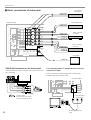
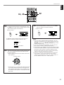
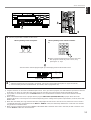
For connecting with a TV monitor that uses a 21 pin
connector for input
Make a connection as figured below with a commercially
available scart-plug connector cable.
PHONO
1
CD
75Ω
UNBAL.
AM
ANT
FM
ANT
GND
AUDIO SIGNAL
GND
TV/DBSCD
CDDVD/LD
TAPE/MD
IN
(PLAY)
OUT
(REC)
DVD/LD
EXTERNAL
DECODER
INPUT
TAPE/MD
3
4
IN
( PLAY )
OUT
( REC )
MAIN
SUB WOOFER
CENTER
SURROUND
DIGITAL
RF SIGNAL
COAXIAL
DIGITAL SIGNAL
OPTICAL
VIDEO
DVD/LD
TV/DBS
IN
VCR 1
OUT
IN
VCR 2
OUT
VIDEO
S VIDEO
DVD/LD
TV/DBS
IN
VCR 1
OUT
IN
VCR 2
OUT
MONITOR
OUT
S VIDEO
AUDIO SIGNAL VIDEO SIGNAL
VIDEO IN
VIDEO OUT
AUDIO OUT
VIDEO OUT
AUDIO OUT
AUDIO OUT
VIDEO OUT
AUDIO IN
VIDEO IN
AUDIO IN
VIDEO IN
AUDIO OUT
VIDEO OUT
(Europe model)
(Europe model)
LD player or
DVD player
TV monitor
No connection
TV monitor
m Basic connections of video units
Video cassette
recorder 2
Scart-plug connector
cable
Video cassette
recorder 1
TV/Satellite tuner
PREPARATION
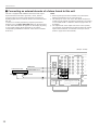
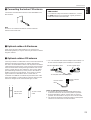
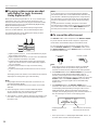
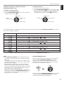
VIDEO AUX terminals (on the front panel)
These terminals are used to connect a video input source such
as a camcorder.
VIDEO AUX
S VIDEO
L
R
VIDEO
VIDEO OUT
S VIDEO OUT
AUDIO OUT L
AUDIO OUT R
Camcorder
: S-video cable
(Refer to page 19 for details
about the S VIDEO terminal.)
IN
VCR 2
OUT
IN
VCR 2
OUT
MAIN
PRE
OUT
MAIN
IN
75Ω
UNBAL.
FM
ANT
GND
COUPLER
TV/DBSCD
CDDVD/LD
TAPE/MD
IN
(PLAY)
OUT
(REC)
DVD/LD
EXTERNAL
DECODER
INPUT
MAIN
SUB WOOFER
CENTER
SURROUND
DIGITAL
RF SIGNAL
COAXIAL
DIGITAL SIGNAL
OPTICAL
VIDEO
S VIDEO
MONITOR
OUT
VIDEO
AUDIO L
AUDIO R

17
English
PREPARATION
Notes
●
When you connect an audio/video unit to both of the digital
and analog terminals of this unit, make sure to connect to
both terminals of the same name.
●
Be sure to attach the covers when the OPTICAL terminals
are not being used, in order to protect the terminals from
dust.
●
In order to make this unit perform successful DTS-decoding,
the DTS bitstream must not be altered, manipulated or
corrupted in the process of sending the DTS bitstream from
the DIGITAL OUT terminal of an external unit to a digital
signal input terminal of this unit.
●
All digital audio signal input terminals are applicable to the
sampling frequency of 32 kHz, 44.1 kHz and 48 kHz.
: Optical fiber cable
: Coaxial cable
PHONO
VIDEO
DVD/LD
TV/DBS
IN
VCR 1
OUT
IN
VCR 2
OUT
VIDEO
S VIDEO
DVD/LD
TV/DBS
IN
VCR 1
OUT
IN
VCR 2
OUT
MONITOR
OUT
S VIDEO
1
CD
75Ω
UNBAL.
AM
ANT
FM
ANT
GND
AUDIO SIGNAL
GND
AUDIO SIGNAL VIDEO SIGNAL
EXTERNAL
DECODER
INPUT
TAPE/MD
3
4
IN
( PLAY )
OUT
( REC )
MAIN
SUB WOOFER
CENTER
SURROUND
TV/DBSCD
CDDVD/LD
TAPE/MD
IN
(PLAY)
OUT
(REC)
DVD/LD
DIGITAL
RF SIGNAL
COAXIAL
DIGITAL SIGNAL
OPTICAL
OPTICAL
DIGITAL OUT
COAXIAL
DIGITAL OUT
OPTICAL
DIGITAL
OUT
OPTICAL
DIGITAL
IN
OPTICAL
DIGITAL
OUT
OPTICAL
DIGITAL
OUT
MD recorder, DAT,
etc.
CD player
TV/Satellite tunerLD player or DVD player
(Europe model)
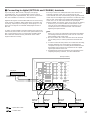
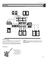
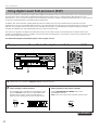
m Connecting to digital (OPTICAL and COAXIAL) terminals
If your CD player, MD recorder, LD player, DVD player,
TV/satellite tuner, etc. are equipped with coaxial or optical
digital audio signal output terminals, they can be connected to
this unit’s COAXIAL or OPTICAL, or both terminals.
Digital audio signals are transmitted with less loss than analog
audio signals. In addition, digital audio signal connections are
necessary, especially for an LD player, a DVD player or a CD
player to send signals encoded with Dolby Digital or DTS to
this unit.
To make an optical digital connection between this unit and an
external unit, remove the cover from each optical terminal, and
then connect them by using a commercially available optical
fiber cable that conforms to EIAJ standards. Other cables
might not function correctly.
Even if you connect an audio/video unit to the OPTICAL (or
COAXIAL) terminal of this unit, you must keep the unit
connected with the same named analog audio signal terminals
of this unit, because digital signal cannot be recorded by a tape
deck or VCR connected to only analog audio signal terminals
of this unit. You can switch the selection of input signals
between “digital” and “analog” easily. (See page 37 for details.)
* However, if you connect an MD recorder or DAT to this
unit’s OPTICAL TAPE/MD IN and OUT terminals, it can
record input sources connected to this unit’s OPTICAL
digital signal input terminals.

18
PHONO
1
CD
75Ω
UNBAL.
AM
ANT
FM
ANT
GND
AUDIO SIGNAL
GND
EXTERNAL
DECODER
INPUT
TAPE/MD
3
4
IN
( PLAY )
OUT
( REC )
MAIN
SUB WOOFER
CENTER
SURROUND
DVD/LD
TV/DBS
IN
VCR 1
OUT
IN
VCR 2
OUT
AUDIO SIGNAL
TV/DBSCD
CDDVD/LD
TAPE/MD
IN
(PLAY)
OUT
(REC)
DVD/LD
DIGITAL
RF SIGNAL
COAXIAL
DIGITAL SIGNAL
OPTICAL
DIGITAL OUT
ANALOG OUT
DOLBY DIGITAL
RF OUT
(Europe model)
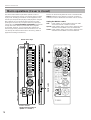
PREPARATION
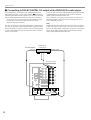
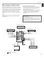
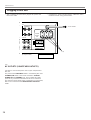
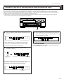
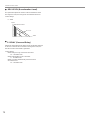
If your DVD/LD/CD combi-player has a DOLBY DIGITAL RF
signal output terminal, connect it to this unit’s DIGITAL RF
SIGNAL input terminal. Audio signals of an LD source encoded
with the Dolby Digital are input to this unit by this connection.
* To play back an LD source with the Dolby Digital decoded,
set the input mode of DVD/LD to “AUTO” or “D.D.RF”.
(Refer to page 37 for details.)
It is also necessary to connect the DVD/LD/CD combi-player to
this unit’s analog audio signal input terminals regardless of the
DOLBY DIGITAL RF signal connection. This is for playing back
a source with Dolby Pro Logic Surround decoded or in normal
stereo (or monaural).
You must also connect the optical digital signal output terminal
of the DVD/LD/CD combi-player to the OPTICAL DVD/LD
digital signal input terminal of this unit.
This connection is necessary for playing back a DVD source
with Dolby Digital or DTS decoded, and playing back an LD
source with DTS decoded.
Note
DOLBY DIGITAL RF audio input signal cannot be recorded by
a tape deck, MD recorder or VCR. To record a source played
back on the DVD/LD/CD combi-player, it must be connected to
the OPTICAL digital audio signal input terminal and analog
audio signal input terminals of this unit.
m Connecting to DOLBY DIGITAL RF output of the DVD/LD/CD combi-player
DVD/LD/CD
combi-player
La page charge ...
La page charge ...
La page charge ...
La page charge ...
La page charge ...
La page charge ...
La page charge ...
La page charge ...
La page charge ...
La page charge ...
La page charge ...
La page charge ...
La page charge ...
La page charge ...
La page charge ...
La page charge ...
La page charge ...
La page charge ...
La page charge ...
La page charge ...
La page charge ...
La page charge ...
La page charge ...
La page charge ...
La page charge ...
La page charge ...
La page charge ...
La page charge ...
La page charge ...
La page charge ...
La page charge ...
La page charge ...
La page charge ...
La page charge ...
La page charge ...
La page charge ...
La page charge ...
La page charge ...
La page charge ...
La page charge ...
La page charge ...
La page charge ...
La page charge ...
La page charge ...
La page charge ...
La page charge ...
La page charge ...
La page charge ...
La page charge ...
La page charge ...
La page charge ...
La page charge ...
La page charge ...
La page charge ...
La page charge ...
La page charge ...
La page charge ...
La page charge ...
La page charge ...
La page charge ...
La page charge ...
La page charge ...
La page charge ...
La page charge ...
La page charge ...
La page charge ...
La page charge ...
La page charge ...
La page charge ...
La page charge ...
-
 1
1
-
 2
2
-
 3
3
-
 4
4
-
 5
5
-
 6
6
-
 7
7
-
 8
8
-
 9
9
-
 10
10
-
 11
11
-
 12
12
-
 13
13
-
 14
14
-
 15
15
-
 16
16
-
 17
17
-
 18
18
-
 19
19
-
 20
20
-
 21
21
-
 22
22
-
 23
23
-
 24
24
-
 25
25
-
 26
26
-
 27
27
-
 28
28
-
 29
29
-
 30
30
-
 31
31
-
 32
32
-
 33
33
-
 34
34
-
 35
35
-
 36
36
-
 37
37
-
 38
38
-
 39
39
-
 40
40
-
 41
41
-
 42
42
-
 43
43
-
 44
44
-
 45
45
-
 46
46
-
 47
47
-
 48
48
-
 49
49
-
 50
50
-
 51
51
-
 52
52
-
 53
53
-
 54
54
-
 55
55
-
 56
56
-
 57
57
-
 58
58
-
 59
59
-
 60
60
-
 61
61
-
 62
62
-
 63
63
-
 64
64
-
 65
65
-
 66
66
-
 67
67
-
 68
68
-
 69
69
-
 70
70
-
 71
71
-
 72
72
-
 73
73
-
 74
74
-
 75
75
-
 76
76
-
 77
77
-
 78
78
-
 79
79
-
 80
80
-
 81
81
-
 82
82
-
 83
83
-
 84
84
-
 85
85
-
 86
86
-
 87
87
-
 88
88
-
 89
89
-
 90
90


Yamaha RX V2095RDS Manuel utilisateur
- Catégorie
- Destinataire
- Taper
- Manuel utilisateur
- Ce manuel convient également à
dans d''autres langues
- italiano: Yamaha RX V2095RDS Manuale utente
- English: Yamaha RX V2095RDS User manual
- español: Yamaha RX V2095RDS Manual de usuario
- Deutsch: Yamaha RX V2095RDS Benutzerhandbuch
- русский: Yamaha RX V2095RDS Руководство пользователя
- Nederlands: Yamaha RX V2095RDS Handleiding
- português: Yamaha RX V2095RDS Manual do usuário
- dansk: Yamaha RX V2095RDS Brugermanual
- polski: Yamaha RX V2095RDS Instrukcja obsługi
- čeština: Yamaha RX V2095RDS Uživatelský manuál
- svenska: Yamaha RX V2095RDS Användarmanual
- Türkçe: Yamaha RX V2095RDS Kullanım kılavuzu
- suomi: Yamaha RX V2095RDS Ohjekirja
- română: Yamaha RX V2095RDS Manual de utilizare
Documents connexes
-
Yamaha DSP-A3090 Manuel utilisateur
-
-
-
-
-
-
-
-
-