Miller MH260636L Le manuel du propriétaire
- Catégorie
- Système de soudage
- Taper
- Le manuel du propriétaire
Ce manuel convient également à

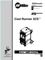
Cool Runner 3CSt
Processes
Description
TIG (GTAW) Welding
OM-230161G 2017-06
File: TIG (GTAW)
MIG (GMAW) Welding
For product information,
Owner’s Manual translations,
and more, visit
www.MillerWelds.com

Miller Electric manufactures a full line
of welders and welding related equipment.
For information on other quality Miller
products, contact your local Miller distributor to receive the latest full
line catalog or individual specification sheets. To locate your nearest
distributor or service agency call 1-800-4-A-Miller, or visit us at
www.MillerWelds.com on the web.
Thank you and congratulations on choosing Miller. Now you can get
the job done and get it done right. We know you don’t have time to do
it any other way.
That’s why when Niels Miller first started building arc welders in 1929,
he made sure his products offered long-lasting value and superior
quality. Like you, his customers couldn’t afford anything less. Miller
products had to be more than the best they could be. They had to be the
best you could buy.
Today, the people that build and sell Miller products continue the
tradition. They’re just as committed to providing equipment and service
that meets the high standards of quality and value established in 1929.
This Owner’s Manual is designed to help you get the most out of your
Miller products. Please take time to read the Safety precautions. They
will help you protect yourself against potential hazards on the worksite.
We’ve made installation and operation quick
and easy. With Miller you can count on years
of reliable service with proper maintenance.
And if for some reason the unit needs repair,
there’s a Troubleshooting section that will
help you figure out what the problem is. The
parts list will then help you to decide the
exact part you may need to fix the problem.
Warranty and service information for your
particular model are also provided.
Miller is the first welding
equipment manufacturer in
the U.S.A. to be registered to
the ISO 9001 Quality System
Standard.
Working as hard as you do
− every power source from
Miller is backed by the most
hassle-free warranty in the
business.
From Miller to You
Mil_Thank 2009−09

TABLE OF CONTENTS
SECTION 1 − SAFETY PRECAUTIONS - READ BEFORE USING 1.................................
1-1. Symbol Usage 1.......................................................................
1-2. Cooling Equipment Hazards 1............................................................
1-3. Additional Symbols For Installation, Operation, And Maintenance 1.............................
1-4. California Proposition 65 Warnings 2......................................................
1-5. Principal Safety Standards 2.............................................................
SECTION 2 − CONSIGNES DE SÉCURITÉ − LIRE AVANT UTILISATION 3...........................
2-1. Symboles utilisés 3.....................................................................
2-2. Dangers liés aux équipements de refroidissement 3.........................................
2-3. Dangers supplémentaires en relation avec l’installation, le fonctionnement et la maintenance 3.....
2-4. Proposition californienne 65 Avertissements 4..............................................
2-5. Principales normes de sécurité 4.........................................................
SECTION 3 − DEFINITIONS 5..................................................................
3-1. Additional Safety Symbols And Definitions 5................................................
3-2. Miscellaneous Symbols And Definitions 6..................................................
SECTION 4 − SPECIFICATIONS 7..............................................................
4-1. Serial Number And Rating Label Location 7................................................
4-2. Specifications 7........................................................................
4-3. Coolant Specifications 7................................................................
4-4. Environmental Specifications 7...........................................................
SECTION 5 − INSTALLATION 8................................................................
5-1. Selecting A Location 8..................................................................
5-2. Installation 9..........................................................................
SECTION 6 − OPERATION 10...................................................................
6-1. Operation 10...........................................................................
6-2. Optional Cooler Connections 11...........................................................
SECTION 7 − MAINTENANCE & TROUBLESHOOTING 12.........................................
7-1. Routine Maintenance 12.................................................................
7-2. Coolant Maintenance 12.................................................................
7-3. Troubleshooting 13......................................................................
SECTION 8 − ELECTRICAL DIAGRAM 13........................................................
8-1. Circuit Diagram For Cooler 13.............................................................
SECTION 9 − PARTS LIST 14...................................................................
COMPLETE PARTS LIST − Available at www.MillerWelds.com
WARRANTY


OM-230161 Page 1
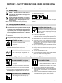
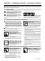
SECTION 1 − SAFETY PRECAUTIONS - READ BEFORE USING
coolers 2016-08
7
Protect yourself and others from injury — read, follow, and save these important safety precautions and operating instructions.
1-1. Symbol Usage
DANGER! − Indicates a hazardous situation which, if
not avoided, will result in death or serious injury. The
possible hazards are shown in the adjoining symbols
or explained in the text.
Indicates a hazardous situation which, if not avoided,
could result in death or serious injury. The possible
hazards are shown in the adjoining symbols or ex-
plained in the text.
NOTICE − Indicates statements not related to personal injury.
. Indicates special instructions.
This group of symbols means Warning! Watch Out! ELECTRIC
SHOCK, MOVING PARTS, and HOT PARTS hazards. Consult sym-
bols and related instructions below for necessary actions to avoid the
hazards.
1-2. Cooling Equipment Hazards
The symbols shown below are used throughout this manual
to call attention to and identify possible hazards. When you
see the symbol, watch out, and follow the related instructions
to avoid the hazard. The safety information given below is
only a summary of the more complete safety information
found in the Safety Standards listed in Section 1-5. Read and
follow all Safety Standards.
Only qualified persons should install, operate, maintain, and
repair this unit.
During operation, keep everybody, especially children, away.
HOT PARTS can burn.
D Do not touch hot parts bare handed.
D Allow cooling period before working on
equipment.
D To handle hot parts, use proper tools and/or wear heavy, insu-
lated welding gloves and clothing to prevent burns.
FLYING METAL or DIRT can injure eyes.
D Wear approved safety glasses with side
shields even under your welding helmet.
Touching live electrical parts can cause fatal shocks
or severe burns. The input power circuit and machine
internal circuits are also live when power is on.
Incorrectly installed or improperly grounded equip-
ment is a hazard.
ELECTRIC SHOCK can kill.
D Do not touch live electrical parts.
D Disconnect input power or stop engine before installing or
servicing this equipment. Lockout/tagout input power according to
OSHA 29 CFR 1910.147 (see Safety Standards).
D Properly install, ground, and operate this equipment according to
its Owner’s Manual and national, state, and local codes.
D Always verify the supply ground − check and be sure that input
power cord ground wire is properly connected to ground terminal in
disconnect box or that cord plug is connected to a properly
grounded receptacle outlet.
D Keep cords dry, free of oil and grease, and protected from hot metal
and sparks.
D Frequently inspect input power cord and ground conductor for
damage or bare wiring – replace immediately if damaged – bare
wiring can kill.
D Turn off all equipment when not in use.
D Use only well-maintained equipment. Repair or replace damaged
parts at once. Maintain unit according to manual.
D Keep all panels and covers securely in place.
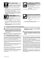
1-3. Additional Symbols For Installation, Operation, And Maintenance
FALLING EQUIPMENT can injure.
D Use equipment of adequate capacity to lift and
support unit.
D If using lift forks to move unit, be sure forks are
long enough to extend beyond opposite side of
unit.
D Keep equipment (cables and cords) away from moving vehicles
when working from an aerial location.
D Follow the guidelines in the Applications Manual for the Revised
NIOSH Lifting Equation (Publication No. 94−110) when manu-
ally lifting heavy parts or equipment.
OVERUSE can cause OVERHEATING
D Allow cooling period; follow rated duty cycle.
D Do not block or filter airflow to unit.
READ INSTRUCTIONS.
D Read and follow all labels and the Owner’s
Manual carefully before installing, operating, or
servicing unit. Read the safety information at
the beginning of the manual and in each
section.
D Use only genuine replacement parts from the manufacturer.
D Perform installation, maintenance, and service according to the
Owner’s Manuals, industry standards, and national, state, and
local codes.
D Read and understand the Safety Data Sheets (SDSs) and the
manufacturer’s instructions for adhesives, coatings, cleaners,
consumables, coolants, degreasers, fluxes, and metals.

OM-230161 Page 2
STEAM AND HOT COOLANT can burn.
Hose may rupture if coolant overheats.
D Visually inspect condition of hoses before each
use. Do not use damaged hoses.
D Allow cooling period before working on equipment.
HIGH PRESSURE FLUIDS can injure or kill.
D Coolant can be under high pressure.
D Release pressure before working on cooler.
D If ANY fluid is injected into the skin or body seek medical help
immediately.
MOVING PARTS can injure.
D Keep away from moving parts such as fans.
D Keep all doors, panels, covers, and guards
closed and securely in place.
D Have only qualified persons remove doors, panels, covers, or
guards for maintenance and troubleshooting as necessary.
D Reinstall doors, panels, covers, or guards when maintenance is
finished and before reconnecting input power.
1-4. California Proposition 65 Warnings
Welding or cutting equipment produces fumes or gases
which contain chemicals known to the State of California to
cause birth defects and, in some cases, cancer. (California
Health & Safety Code Section 25249.5 et seq.)
This product contains or produces a chemical known to the
state of California to cause cancer or birth defects (or other
reproductive harm). (California Health & Safety Code Section
25249.5 et seq.)
This product contains chemicals, including lead, known to
the state of California to cause cancer, birth defects, or other
reproductive harm. Wash hands after use.
1-5. Principal Safety Standards
Safety in Welding, Cutting, and Allied Processes, ANSI Standard Z49.1,
is available as a free download from the American Welding Society at
http://www.aws.org or purchased from Global Engineering Documents
(phone: 1-877-413-5184, website: www.global.ihs.com).
Safe Practices for the Preparation of Containers and Piping for Welding
and Cutting, American Welding Society Standard AWS F4.1, from Glob-
al Engineering Documents (phone: 1-877-413-5184, website:
www.global.ihs.com).
Safe Practices for Welding and Cutting Containers that have Held Com-
bustibles, American Welding Society Standard AWS A6.0, from Global
Engineering Documents (phone: 1-877-413-5184,
website: www.global.ihs.com).
National Electrical Code, NFPA Standard 70, from National Fire Protec-
tion Association, Quincy, MA 02269 (phone: 1-800-344-3555, website:
www.nfpa.org and www. sparky.org).
Safe Handling of Compressed Gases in Cylinders, CGA Pamphlet P-1,
from Compressed Gas Association, 14501 George Carter Way, Suite
103, Chantilly, VA 20151 (phone: 703-788-2700, website:
www.cganet.com).
Safety in Welding, Cutting, and Allied Processes, CSA Standard
W117.2, from Canadian Standards Association, Standards Sales, 5060
Spectrum Way, Suite 100, Mississauga, Ontario, Canada L4W 5NS
(phone: 800-463-6727, website: www.csagroup.org).
Safe Practice For Occupational And Educational Eye And Face Protec-
tion, ANSI Standard Z87.1, from American National Standards Institute,
25 West 43rd Street, New York, NY 10036 (phone: 212-642-4900, web-
site: www.ansi.org).
Standard for Fire Prevention During Welding, Cutting, and Other Hot
Work, NFPA Standard 51B, from National Fire Protection Association,
Quincy, MA 02269 (phone: 1-800-344-3555, website: www.nfpa.org).
OSHA, Occupational Safety and Health Standards for General Indus-
try, Title 29, Code of Federal Regulations (CFR), Part 1910, Subpart Q,
and Part 1926, Subpart J, from U.S. Government Printing Office, Super-
intendent of Documents, P.O. Box 371954, Pittsburgh, PA 15250-7954
(phone: 1-866-512-1800) (there are 10 OSHA Regional Offices—
phone for Region 5, Chicago, is 312-353-2220, website:
www.osha.gov).
Applications Manual for the Revised NIOSH Lifting Equation, The Na-
tional Institute for Occupational Safety and Health (NIOSH), 1600
Clifton Rd, Atlanta, GA 30329-4027 (phone: 1-800-232-4636, website:
www.cdc.gov/NIOSH).

OM-230161 Page 3
SECTION 2 − CONSIGNES DE SÉCURITÉ − LIRE AVANT UTILISATION
Cooler 2016−08_fre
Pour écarter les risques de blessure pour vous−même et pour autrui — lire, appliquer et ranger en lieu sûr ces consignes relatives
aux précautions de sécurité et au mode opératoire.
2-1. Symboles utilisés
DANGER! − Indique une situation dangereuse qui si on
l’évite pas peut donner la mort ou des blessures graves.
Les dangers possibles sont montrés par les symboles
joints ou sont expliqués dans le texte.
Indique une situation dangereuse qui si on l’évite pas
peut donner la mort ou des blessures graves. Les
dangers possibles sont montrés par les symboles
joints ou sont expliqués dans le texte.
AVIS − Indique des déclarations pas en relation avec des blessures
personnelles.
. Indique des instructions spécifiques.
Ce groupe de symboles veut dire Avertissement! Attention! DANGER
DE CHOC ELECTRIQUE, PIECES EN MOUVEMENT, et PIECES
CHAUDES. Consulter les symboles et les instructions ci-dessous y
afférant pour les actions nécessaires afin d’éviter le danger.
2-2. Dangers liés aux équipements de refroidissement
Les symboles représentés ci-dessous sont utilisés dans ce
manuel pour attirer l’attention et identifier les dangers possibles.
En présence de l’un de ces symboles, prendre garde et suivre
les instructions afférentes pour éviter tout risque. Les
instructions en matière de sécurité indiquées ci-dessous ne
constituent qu’un sommaire des instructions de sécurité plus
complètes fournies dans les normes de sécurité énumérées
dans la Section 2-5. Lire et observer toutes les normes de
sécurité.
Seul un personnel qualifié est autorisé à installer, faire
fonctionner, entretenir et réparer cet appareil.
Pendant le fonctionnement, maintenir à distance toutes les
personnes, notamment les enfants de l’appareil.
LES PIÈCES CHAUDES peuvent
provoquer des brûlures.
D Ne pas toucher à mains nues les partie
s
chaudes.
D Prévoir une période de refroidissement avant d
e
travailler à l’équipement.
D Ne pas toucher aux pièces chaudes, utiliser les outils recomman
-
dés et porter des gants de soudage et des vêtements épais pou
r
éviter les brûlures.
DES PIECES DE METAL ou DES
SALETES peuvent provoquer des
blessures dans les yeux.
D Porter des lunettes de sécurité avec écrans
latéraux ou un écran facial.
Le contact d’organes électriques sous tension peut
provoquer des accidents mortels ou des brûlures
graves. Le circuit d’alimentation et les circuits
internes de la machine sont également sous tension
lorsque l’alimentation est sur Marche. Un équipement installé ou mis
à la terre de manière incorrecte ou impropre constitue un danger.
UNE DÉCHARGE ÉLECTRIQUE peut
entraîner la mort.
D Ne pas toucher aux pièces électriques sous tension.
D Couper l’alimentation ou arrêter le moteur avant de procéder
à l’installation, à la réparation ou à l’entretien de l’appareil.
Déverrouiller l’alimentation selon la norme OSHA 29 CFR
1910.147 (voir normes de sécurité).
D Installez, mettez à la terre et utilisez correctement cet équipement
conformément à son Manuel d’Utilisation et aux réglementations
nationales, gouvernementales et locales.
D Toujours vérifier la terre du cordon d’alimentation. Vérifier et
s’assurer que le fil de terre du cordon d’alimentation est bien
raccordé à la borne de terre du sectionneur ou que la fiche du
cordon est raccordée à une prise correctement mise à la terre.
D Les câbles doivent être exempts d’humidité, d’huile et de graisse;
protégez−les contre les étincelles et les pièces métalliques
chaudes.
D Vérifier fréquemment le cordon d’alimentation afin de s’assurer
qu’il n’est pas altéré ou à nu, le remplacer immédiatement s’il l’est.
Un fil à nu peut entraîner la mort.
D L’équipement doit être hors tension lorsqu’il n’est pas utilisé.
D N’utiliser qu’un matériel en bon état. Réparer ou remplacer
sur-le-champ les pièces endommagées. Entretenir l’appareil
conformément à ce manuel.
D S’assurer que tous les panneaux et couvercles sont correctement
en place.
2-3. Dangers supplémentaires en relation avec l’installation, le fonctionnement et la maintenance
LA CHUTE DE L’ÉQUIPEMENT peut
provoquer des blessures.
D Utiliser un équipement de levage de capacité
suffisante pour lever l’appareil.
D En utilisant des fourches de levage pour
déplacer l’unité, s’assurer que les fourches
sont suffisamment longues pour dépasser du
côté opposé de l’appareil.
D Tenir l’équipement (câbles et cordons) à distance des véhicules
mobiles lors de toute opération en hauteur.
D Suivre les consignes du Manuel des applications pour l’équation
de levage NIOSH révisée (Publication Nº94–110) lors du levage
manuelle de pièces ou équipements lourds.
L’EMPLOI EXCESSIF peut
SURCHAUFFER L’ÉQUIPEMENT.
D Prévoir une période de refroidissement ;
respecter le cycle opératoire nominal.
D Ne pas obstruer les passages d’air du poste.

OM-230161 Page 4
LIRE LES INSTRUCTIONS.
D Lire et appliquer les instructions sur les
étiquettes et le Mode d’emploi avant
l’installation, l’utilisation ou l’entretien de
l’appareil. Lire les informations de sécurité au
début du manuel et dans chaque section.
D N’utiliser que les pièces de rechange recommandées par le
constructeur.
D Effectuer l’installation, l’entretien et toute intervention selon les
manuels d’utilisateurs, les normes nationales, provinciales et de
l’industrie, ainsi que les codes municipaux.
D Lire et comprendre les fiches de données de sécurité et les
instructions du fabricant concernant les adhésifs, les revêtements,
les nettoyants, les consommables, les produits de refroidissement,
les dégraisseurs, les flux et les métaux.
Les PIÈCES MOBILES peuvent
causer des blessures.
D S’abstenir de toucher des organes mobiles tels
que des ventilateurs.
D Maintenir fermés et verrouillés les portes,
panneaux, recouvrements et dispositifs de
protection.
D Lorsque cela est nécessaire pour des travaux d’entretien et de
dépannage, faire retirer les portes, panneaux, recouvrements
ou dispositifs de protection uniquement par du personnel
qualifié.
D Remettre les portes, panneaux, recouvrements ou dispositifs de
protection quand l’entretien est terminé et avant de rebrancher
l’alimentation électrique.
LA VAPEUR ET LE LIQUIDE DE
REFROIDISSEMENT CHAUD peuvent
provoquer des brûlures.
Un tuyau peut se rompre lorsque le liquide de
refroidissement surchauffe.
D Vérifiez visuellement l’état des tuyaux avant
chaque utilisation. N’utilisez pas de tuyaux
endommagés.
D Laissez refroidir avant d’intervenir sur l’équipement.
LES LIQUIDES SOUS HAUTE PRESSION
peuvent provoquer des blessures ou la
mort.
D Liquide de refroidissement sous haute
pression.
D Libérez la pression avant d’intervenir sur le
refroidisseur.
D En cas d’injection d’un liquide QUELCONQUE dans la peau ou
le corps, consultez immédiatement un médecin.
2-4. Proposition californienne 65 Avertissements
Les équipements de soudage et de coupage produisent des
fumées et des gaz qui contiennent des produits chimiques
dont l’État de Californie reconnaît qu’ils provoquent des
malformations congénitales et, dans certains cas, des
cancers. (Code de santé et de sécurité de Californie, chapitre
25249.5 et suivants)
Ce produit contient ou forme un produit chimique reconnu
par l’état de Californie de provoquer le cancer ou
malformations de naissance (ou autre problèmes
reproductifs. (Code de santé et de sécurité de Californie,
chapitre 25249.5 et suivants).
Ce produit contient des produits chimiques, notamment du
plomb, dont l’État de Californie reconnaît qu’ils provoquent
des cancers, des malformations congénitales ou d’autres
problèmes de procréation. Se laver les mains après
utilisation.
2-5. Principales normes de sécurité
Safety in Welding, Cutting, and Allied Processes, ANSI Standard Z49.1,
is available as a free download from the American Welding Society at
http://www.aws.org or purchased from Global Engineering Documents
(phone: 1-877-413-5184, website: www.global.ihs.com).
Safe Practices for the Preparation of Containers and Piping for Welding
and Cutting, American Welding Society Standard AWS F4.1, from
Global Engineering Documents (phone: 1-877-413-5184, website:
www.global.ihs.com).
Safe Practices for Welding and Cutting Containers that have Held
Combustibles, American Welding Society Standard AWS A6.0, from
Global Engineering Documents (phone: 1-877-413-5184,
website: www.global.ihs.com).
National Electrical Code, NFPA Standard 70, from National Fire
Protection Association, Quincy, MA 02269 (phone: 1-800-344-3555,
website: www.nfpa.org and www. sparky.org).
Safe Handling of Compressed Gases in Cylinders, CGA Pamphlet P-1,
from Compressed Gas Association, 14501 George Carter Way, Suite
103, Chantilly, VA 20151 (phone: 703-788-2700, website:
www.cganet.com).
Safety in Welding, Cutting, and Allied Processes, CSA Standard
W117.2, from Canadian Standards Association, Standards Sales, 5060
Spectrum Way, Suite 100, Mississauga, Ontario, Canada L4W 5NS
(phone: 800-463-6727, website: www.csagroup.org).
Safe Practice For Occupational And Educational Eye And Face
Protection, ANSI Standard Z87.1, from American National Standards
Institute, 25 West 43rd Street, New York, NY 10036 (phone:
212-642-4900, website: www.ansi.org).
Standard for Fire Prevention During Welding, Cutting, and Other Hot
Work, NFPA Standard 51B, from National Fire Protection Association,
Quincy, MA 02269 (phone: 1-800-344-3555, website: www.nfpa.org).
OSHA, Occupational Safety and Health Standards for General
Industry, Title 29, Code of Federal Regulations (CFR), Part 1910,
Subpart Q, and Part 1926, Subpart J, from U.S. Government Printing
Office, Superintendent of Documents, P.O. Box 371954, Pittsburgh, PA
15250-7954 (phone: 1-866-512-1800) (there are 10 OSHA Regional
Offices—phone for Region 5, Chicago, is 312-353-2220, website:
www.osha.gov).
Applications Manual for the Revised NIOSH Lifting Equation, The
National Institute for Occupational Safety and Health (NIOSH), 1600
Clifton Rd, Atlanta, GA 30329-4027 (phone: 1-800-232-4636, website:
www.cdc.gov/NIOSH).

. A complete Parts List is available at www.MillerWelds.com
OM-230161 Page 5
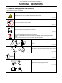
SECTION 3 − DEFINITIONS
3-1. Additional Safety Symbols And Definitions
. Some symbols are found only on CE products.
Warning! Watch Out! There are possible hazards as shown by the symbols.
Safe1 2012−05
Do not remove or paint over (cover) the label.
Safe20 2017−04
Disconnect input plug or power before working on machine.
Safe30 2012−05
Do not discard product (where applicable) with general waste.
Reuse or recycle Waste Electrical and Electronic Equipment (WEEE) by disposing at a designated collection
facility.
Contact your local recycling office or your local distributor for further information.
Safe37 2017−04
Safe50 2012−05
Plugged filter or hoses can cause overheating to the power source
and torch.
100 h. Std.
Safe51 2012−05
Every 100 hours, check and clean filter and check condition of hoses.
XXXXX
Use coolant suggested by the manufacturer: 043810 (HF), 043809 (Al).
Safe52 2012−05
Read the labels on the welding power source, wire feeder, or other
major equipment for welding safety information.
Safe71 2012−06
Read the Owner’s Manual before working on this machine.
Safe70 2012−06

. A complete Parts List is available at www.MillerWelds.com
OM-230161 Page 6
3-2. Miscellaneous Symbols And Definitions
. Some symbols are found only on CE products.
Line Connection
U
1
Primary Voltage
IP
Degree Of
Protection
Power On
Indicator
Hz
Hertz
Input Power
P
1max
Maximum Power
Consumption
Pl/
min
Power Liters Per
Minute
I
1max
Rated Maximum
Supply Current
Water (Coolant)
Output
Water (Coolant)
Input
Single
Phase
Notes
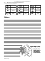
Work like a Pro!
Pros weld and cut
safely. Read the
safety rules at
the beginning
of this manual.

OM-230161 Page 7
SECTION 4 − SPECIFICATIONS
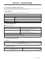
4-1. Serial Number And Rating Label Location
The serial number and rating information for this product is located on the front. Use rating label to determine input power requirements and/or rated
output. For future reference, write serial number in space provided on back cover of this manual.
4-2. Specifications
. The correction factor on the cooling power at an ambient temperature of 1045F (405C) is 0.625.
Recirculating Coolant System For Water-Cooled GTAW Torches And GMAW Guns
Use With Guns/Torches Rated Up To 400 Amperes
Coolant Tank Capacity 3 gal (11.4 L) Coolant Tank Capacity; Flow Rate Is 1 Liter Per Minute (1.1 Quarts)
Dimensions (Length x Width x Height) Cooling Unit Dimensions: 25-5/8 in (651 mm) Long, 19-13/16 in (503 mm) Wide, 10-3/4 in (273 mm) High;
Base Dimensions: 25-15/16 in. (659 mm) Long, 22-1/4 in. (565 mm) Wide, 11-15/16 in. (659 mm) High
Weight 40 lb (18Kg)
Input Voltage 115 VAC, Single Phase, 50 or 60 Hz
Input Amperage 5.9 A 60 Hz
4-3. Coolant Specifications
Do not use conductive coolant.
Application Coolant
GTAW Or Where High Frequency Current Is Used Low Conductivity Coolant 043810*
Distilled Or Deionized Water Okay Above 32°F (0°C)
GMAW Or Where High Frequency Current Is Not Used Low Conductivity Coolant 043810*
Aluminum Protecting Coolant 043809*
Distilled Or Deionized Water Okay Above 32°F (0°C)
Where Coolant Contacts Aluminum Parts Aluminum Protecting Coolant 043809*
*Coolants 043810 and 043809 protect to -37°F (-38°C) and resist algae growth.
NOTICE − Use of any coolant other than those listed in the table voids the warranty on any parts that come in contact with the coolant (pump, radiator,
etc.).
4-4. Environmental Specifications
A. IP Rating
IP Rating
IP23
This equipment is designed for outdoor use.
IP23 2017−02
B. Temperature Specifications
Operating Temperature Range Storage/Transportation Temperature Range
14 to 104 °F (-10 to 40°C)
−4 to 131°F (−20 to 55°C)
Temp1_2016- 08

OM-230161 Page 8
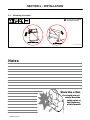
SECTION 5 − INSTALLATION
5-1. Selecting A Location
! Do not move or operate
unit where it could tip.
Loc_cooler 2016-08
Notes
Work like a Pro!
Pros weld and cut
safely. Read the
safety rules at
the beginning
of this manual.

OM-230161 Page 9
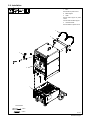
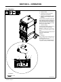
5-2. Installation
1
2
3
4
4
Tools Needed:
3/8 in.
9/16 in.
805139-C
1 Base
Secure base to power source.
2 Bottle Support
3 Chain
Secure bottle support to power
source.
Connect chain to bottle support.
4 Universal Handle
Secure handles to power source.

OM-230161 Page 10
SECTION 6 − OPERATION
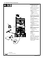
6-1. Operation
805102-B / 805517-A
Tools Needed:
11/16 in.
1
3
2
5
6
Front Of Cooling Unit
4
or
1 Coolant Tank Cap
2 Coolant In Fitting
3 Coolant Hose (Customer Supplied -
Not Required On All Models)
4 TIG Block Or International Style Water
Adapter (Customer Supplied - Varies
By Model)
Connect coolant hose between Coolant In fit-
ting and TIG block located on welding power
source Electrode weld output terminal, or
connect international style water adapter to
Electrode weld output terminal and adapter
water hose to Coolant In fitting.
5 Coolant Out Fitting
Connect hoses between cooling unit and
torch cable/TIG block coolant fittings.
NOTICE − If welding power source has a wa-
ter valve, do not connect hoses to water
valve.
See Section 6 to select proper coolant, and fill
tank. Keep coolant level full.
Operation:
6 Flowmeter
To turn cooling unit On, connect power cord
to welding power source 115 volts ac recep-
tacle. Unplug to turn unit Off.
Flow indicator spins to indicate that at least
1.1 qt/min (1.0 L/min) of coolant is flowing.

OM-230161 Page 11
6-2. Optional Cooler Connections
805102-B
Tools Needed:
11/16 in. (21 mm for CE units)
! Disconnect cooler plug from
welding power source re-
ceptacle before filling.
1 Cap
Remove cap and fill tank with three
gallons of coolant (see Section 6).
2 Gas Out Connection
Connect TIG torch gas hose to gas
out fitting.
3 Electrode Weld Output
Terminal
4 TIG Block (Customer Sup-
plied)
Connect TIG torch to electrode
weld output terminal. Note: Some
models may require a TIG block
instead of the international style
water connector.
5 Remote 14 Receptacle
Connect remote control to recep-
tacle if desired.
6 Work Weld Output Terminal
Connect work lead to work weld
output terminal.
7 Water-In (From Torch)
Connection
Connect torch water-out (red) hose
to welding power source water-in
connection.
NOTICE − If welding power source
has a water valve, do not connect
hoses to water valve.
8 Water-Out (To Torch)
Connection
Connect torch water-in (blue) hose
to welding power source water-out
connection.
Operation:
9 115 VAC Cord
10 Flowmeter
To turn cooling unit On, connect
power cord to welding power
source 115 volts AC receptacle.
Unplug to turn unit Off.
Flow indicator spins to indicate that
at least 1.1 qt/min (1.0 L/min) of
coolant is flowing.
1
3
5
6
7
2
8
9
4
10

OM-230161 Page 12
SECTION 7 − MAINTENANCE & TROUBLESHOOTING
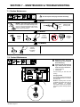
7-1. Routine Maintenance
! Turn Off all power and unplug unit before maintaining.
1 Month
Blow Out Heat
Exchanger Fins
NOTICE − Clean coolant strainer. Severe condi-
tions may require more frequent cleaning (contin-
uous use, high/low temperatures, dirty environ-
ment, etc.). Failure to properly clean coolant
strainer voids pump warranty.
6 Months
Replace
Cracked
Hoses
Replace
Unreadable
Labels
Change
Coolant (If
Using Water)
12 Months
Change
Coolant (If
Using Miller
Coolant)
7-2. Coolant Maintenance
805516-A / Coolant 2016-08
1
! Disconnect cooler plug from
welding power source receptacle
before maintaining.
! Dispose of used coolant accord-
ing to national, state, and local
codes. Do not pour down drain.
1 Cooler Front Panel
2 Coolant Filter
Unscrew housing to clean filter and
housing.
Changing Coolant
Drain coolant by tipping unit forward. Fill
with clean water and run for 10 minutes.
Drain and refill.
NOTICE − If replacing hoses, use hoses
compatible with ethylene glycol, such as
Buna-n, Neoprene, or Hypalon.
Oxy-acetylene hoses are not compati-
ble with any product containing ethylene
glycol.
2

OM-230161 Page 13
7-3. Troubleshooting
Trouble Remedy
Coolant system does not work. Be sure input power cord is plugged into energized receptacle.
Check line fuses or circuit breaker, and replace or reset if necessary.
Motor overheated. Unit starts running when motor has cooled.
Have Factory Authorized Service Agent check motor.
Decreased or no coolant flow. Add coolant.
Check for clogged hoses or coolant filter.
Disconnect pump, and check for sheared coupling. Replace coupling if necessary.
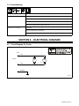
SECTION 8 − ELECTRICAL DIAGRAM
8-1. Circuit Diagram For Cooler
BLK
WHT
GRN/YEL
11
12
MOT
PLG1
115VAC.
FM
225650-A

OM-230161 Page 14
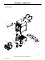
SECTION 9 − PARTS LIST
805100-D
. Hardware is common and
not available unless listed.
1
2
3
4
5
6
7
15
11
12
14
8
9
10
13
18
19
16
16
Figure 9-1. Running Gear For Cool Runner 3CS

OM-230161 Page 15
Description
Part
No.
Dia.
Mkgs.
Item
No.
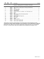
Figure 9-1. Running Gear For Cool Runner 3CS Cooler
Quantity
1 +215928 Bottle Support 1... ......... .. ......................................................
2 228542 Label, Warning Cyl May Explode If Damaged (ENG/FR/SP) 1 ... .......... .. ..............
3 602387 Chain 2... .......... .. .............................................................
4 168663 Hook Spring Snap 3... .......... .. ..................................................
5 231344 Tray Assy, Bottle 1... .......... .. ....................................................
6 121614 Retaining Ring 2... .......... .. ......................................................
7 602250 Washer, Flat .812 Id x 1.469 Od x .134 T Stl Pld Ansi .750 2... .......... .. ...............
8 209869 Wheel 2... .......... .. .............................................................
9 +233120 Base 1... ......... .. ..............................................................
10 230366 Label, Warning General Precautionary Static 2... .......... .. ...........................
11 168247 Caster, Swivel 2... .......... .. ......................................................
12 231336 Cool Unit, 3CS (See Figure 9-2) 1... .......... .. ......................................
13 233121 Beam, Caster 1... .......... .. .....................................................
14 196312 Guard, Fan 1... .......... .. .......................................................
15 235506 Spacer 2... .......... .. ...........................................................
16 242337 Handle, Universal 2... .......... .. ..................................................
18 220182 Screw, 10−24 x 3.00 Soc Hd 2... .......... .. .........................................
19 217802 Wrench, Allen T-Handle 5/32 1... .......... .. .........................................
+When ordering a component originally displaying a precautionary label, the label should also be ordered.
To maintain the factory original performance of your equipment, use only Manufacturer’s Suggested
Replacement Parts. Model and serial number required when ordering parts from your local distributor.
BE SURE TO PROVIDE MODEL AND SERIAL NUMBER WHEN ORDERING REPLACEMENT PARTS.

OM-230161 Page 16
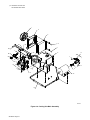
. Hardware is common and
not available unless listed.
1
2
3
6
7
9
7
10
8
11
12
13
14
15
16
17
18
19
20
21
22
23
28
25
26
7
27
24
29
30
4
5
804995-A
Figure 9-2. Cooling Unit Main Assembly
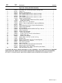
La page est en cours de chargement...
La page est en cours de chargement...
La page est en cours de chargement...
La page est en cours de chargement...
-
 1
1
-
 2
2
-
 3
3
-
 4
4
-
 5
5
-
 6
6
-
 7
7
-
 8
8
-
 9
9
-
 10
10
-
 11
11
-
 12
12
-
 13
13
-
 14
14
-
 15
15
-
 16
16
-
 17
17
-
 18
18
-
 19
19
-
 20
20
-
 21
21
-
 22
22
-
 23
23
-
 24
24


Miller MH260636L Le manuel du propriétaire
- Catégorie
- Système de soudage
- Taper
- Le manuel du propriétaire
- Ce manuel convient également à
dans d''autres langues
- English: Miller MH260636L Owner's manual
Documents connexes
-
Miller MJ490713L Le manuel du propriétaire
-
Miller FLOWMAX Le manuel du propriétaire
-
-
-
-
-