CREE LIGHTING CR-B LDE1_PSQ0 Guide d'installation
- Catégorie
- Accessoires de moto
- Taper
- Guide d'installation

CR-B Series
LED Architectural Troffer
Includes: CR14-B-LDE1/PSQ0, CR22-B-LDE1/PSQ0, CR24-B-LDE1/PSQ0
LPN05500X0005A0_A
1 of 3
INSTALLATION INSTRUCTIONS
INSTRUCTIONS D’INSTALLATION
CR22-B-LDE1
CR22-B-PSQ0
CR24-B-LDE1
CR24-B-PSQ0
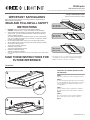
TO INSTALL CRB SERIES ARCHITECTURAL
LED TROFFERS:
STEP 1:
Unpack the CR-B troffer from its shipping container.
STEP 2:
For units without power whip option, proceed to STEP 3.
For units equipped with power whip, install access plate
cover attached to power whip onto luminaire using
screw provided.
STEP 3:
Install the (4) T-Bar clips included with the luminaire
(located in pre-pack fastened to luminaire J-Box). See
Figure 1.
STEP 4:
Place the CR-B troffer into the T-Bar Ceiling panel.
Ensure T-Bar clips are attached to the T-Bar. See
Figure 2.
TO INSTALL:
• The CR-B Series of recessed troffers is for non-insulated
ceiling applications using T-Bar ceiling grid, drywall grid
adaptors, and surface mount accessory kits.
CR14-B-LDE1
CR14-B-PSQ0
IMPORTANT SAFEGUARDS
When using electrical equipment, basic safety precautions should always be
followed including the following:
READ AND FOLLOW ALL SAFETY
INSTRUCTIONS
1. DANGER- Risk of shock- Disconnect power before installation.
DANGER – Risque de choc – Couper l’alimentation avant l’installation.
2. This luminaire must be installed in accordance with the NEC or your local
electrical code. If you are not familiar with these codes and requirements,
consult a qualied electrician.
Ce produit doit être installé conformément à NEC ou votre code électrique
local. Si vous n’êtes pas familier avec ces codes et ces exigences, veuillez
contacter un électricien qualié.
3. Do not install insulation within 76 mm (3 in) of any part of the luminaire.
Ne pas mettre l’isolant à moins de 76 mm (3 po) de toute partie du luminaire.
4. Access above ceiling required.
Accès requis au-dessus du plafond.
5. Suitable for damp locations.
Convient aux emplacements humide.
6. Suitable for suspended ceilings.
Adaptee aux plafonds suspendus.
7. Do not handle energized module with wet hands or when standing on wet or damp surfaces,
or in water.
SAVE THESE INSTRUCTIONS FOR
FUTURE REFERENCE
1
2

LPN05500X0005A0_A
2 of 3
POWER SUPPLY WIRING AND
LDE1/PSQ0 SETUP:
OPTION: Power whip (if installed), skip STEPS 1-4.
Refer directly to ELECTRICAL CONNECTIONS to wire
flying leads.
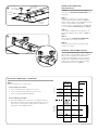
STEP 1:
Remove access plates to access the power wiring
chamber and control wiring chamber. See Figure 3.
Using screw driver blade, remove appropriate knockouts
from access plates and route input conduit.
If more wire space is needed, utilize the expanded J-Box
accessory EJBCR-5PK (sold separately). See Figure 4.
STEP 2:
Connect power conduit and control conduit to access
plates (and expanded J-Box if needed). See Figure 3
and 4.
STEP 3:
Wire luminaire per ELECTRICAL CONNECTIONS
section. Make sure no wires are pinched.
STEP 4:
Push all wires back into the junction boxes and
reinstall access plates.
EXPANDED JBOX ASSEMBLY OPTION:
In the case of through wiring with conductors larger
than 14 gauge, it is recommended to utilize the EJBCR-
5PK accessory to expand the junction box volume,
thereby allowing for additional space for wiring and
wiring fasteners. EJBCR-5PK is supplied separately
and attaches to existing J-Box assembly. It is sold in
minimum quantities of five. See Figure 4.
4
3Access Plate to
Power Supply
Junction Box
Power Supply
Junction Box
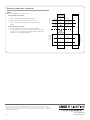
ELECTRICAL CONNECTIONS LUTRON LDE1
STEP 1:
Make the following Electrical Connections:
In Power Supply Junction Box:
a. Connect the black fixture lead to the line or Hot 1.
b. Connect the white fixture lead to the neutral or Hot 2.
c. Connect the bare ground lead to ground.
In Control Wiring Junction Box:
d. If EcoSystem Digital Link is used, connect the pink (E1) and violet
(E2) leads to a Lutron EcoSystem Digital Link (Polarity-free). If not
used, ensure to cap off the grey or pink and violet leads. Refer to
www.lutron.com for additional details.
LINE
OR HOT 1
GROUND
LINE-BLACK
GROUND-BARE
NEUTRAL-WHITE
E2 VIOLET
NEUTRAL
OR HOT 2
E2 VIOLET
SUPPLY WIRING
(OPTIONAL CONTROL
LINES)
TO A LUTRON
ECO SYSTEM
DIGITAL LINK
E1 PINKE1 PINK
POWER SUPPLY
JUNCTION BOX
CONTROL
WIRING
JUNCTION BOX
LUMINAIRE
Access Plate to
Control Wiring
Junction Box
Control Wiring
Junction Box

LPN05500X0005A0_A
3 of 3
© 2023 Cree Lighting®, A company of IDEAL INDUSTRIES. All rights reserved. For informational purposes only.
Content is subject to change. See www.creelighting.com/warranty for warranty and specifications. Cree® and the Cree
Lighting logo are registered trademarks of Cree, Inc. CR14™, CR22™ and CR24™ are trademarks of Cree Lighting, A
company of IDEAL INDUSTRIES.
www.creelighting.com
ELECTRICAL CONNECTIONS LUTRON PSQ0
STEP 1:
Make the following Electrical Connections:
In Power Supply Junction Box:
a. Connect the black fixture lead to the line or Hot 1.
b. Connect the white fixture lead to the neutral or Hot 2.
c. Connect the bare ground lead (in power wiring chamber) to
ground.
In Control Wiring Junction Box:
d. If T-Series Digital Link is used, connect the pink (T1) and
violet (T2) leads to a Lutron T-Series Digital Link (Polarity-free). If
not used, ensure to cap off the grey or pink and violet leads. Refer
to www.lutron.com for additional details.
LINE
OR HOT 1
GROUND
LINE-BLACK
GROUND-BARE
NEUTRAL-WHITE
T2 VIOLET
NEUTRAL
OR HOT 2
T2 VIOLET
SUPPLY WIRING
(OPTIONAL CONTROL
LINES)
TO A LUTRON
ECO SYSTEM
DIGITAL LINK
T1 PINKT1 PINK
POWER SUPPLY
JUNCTION BOX
CONTROL
WIRING
JUNCTION BOX
LUMINAIRE
-
 1
1
-
 2
2
-
 3
3


CREE LIGHTING CR-B LDE1_PSQ0 Guide d'installation
- Catégorie
- Accessoires de moto
- Taper
- Guide d'installation