GE J2S968BEKBB Guide d'installation
- Catégorie
- Cuisinières
- Taper
- Guide d'installation
Ce manuel convient également à

1
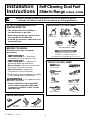
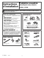
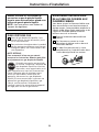
MATERIALS YOU MAY NEED
31-10626-2 1-07 JR
Questions? Call 800.GE.CARES (800.432.2737) or Visit our Website at: ge.com
In Canada, call 1.800.361.3400 or Visit our Website at: www.geappliances.ca
Installation
Self-Cleaning Dual Fuel
Instructions
Slide-In Range
J2S968, J2C968
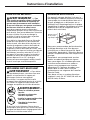
BEFORE YOU BEGIN
Read these instructions completely
and carefully.
•
IMPORTANT — Save these
instructions for local inspector’s use.
•
IMPORTANT — Observe all
governing codes and ordinances.
• Note to Installer – Be sure to leave these
instructions with the Consumer.
• Note to Consumer – Keep these
instructions for future reference.
• Product failure due to improper installation
is not covered under the Warranty.
WARNING — This appliance must
be properly grounded.
• Proper installation is the responsibility
of the installer and product failure due
to improper installation is NOT covered
under warranty.
IN THE COMMONWEALTH OF
MASSACHUSETTS:
• This product must be installed by a
licensed plumber or gas fitter.
• When using ball-type gas shut-off valves,
they shall be the T-handle type.
• A flexible gas connector, when used, must
not exceed 3 feet.
PARTS INCLUDED
Anti-Tip Bracket
Anchor Sleeves
Lag Bolts
(For Concrete Floors Only)
Shut Off Valve
Pipe Fittings
CSA-Approved Flexible Gas Line
3/8″ Min. ID, 1/2″ NPT Connection,
3-foot Maximum Length (Massachusetts only)
Joint Sealant
Wrench or Pliers
(for 1-7/16” Nut)
Level
1/4” Nut Driver
Safety Glasses Drill
Tape Measure
Screws
Rear Filler
2 Screws
Phillips Head
Screwdriver
Pipe Wrench
TOOLS YOU WILL NEED

2
Installation Instructions
FOR YOUR SAFETY:
WARNING — If the information in
this manual is not followed exactly, a fire,
explosion or gas leak may result causing
property damage, personal injury or death.
Do not store or use gasoline or other
flammable vapors and liquids in the vicinity
of this or any other appliance!
WHAT TO DO IF YOU
SMELL GAS:
• Do not try to light any appliance. Do not
touch any electrical switch; do not use any
phone in your building.
• Immediately call your gas supplier from a
neighbor’s phone. Follow the gas supplier’s
instructions.
• If you cannot reach your gas supplier,
call the fire department.
Installation and service must be performed
by a qualified installer, service agency or
the gas supplier.
IMPORTANT SAFETY INSTRUCTIONS
This range has been design certified by
UNDERWRITERS LABORATORIES for use in
the United States and Canada. You’ll find
safety precautions in your Owner’s Manual.
Read them carefully.
• Installation of this range must conform with
local codes or in the absence of local codes
with the National Fuel Gas Code, ANSI
Z223.1–Latest edition.
• Be sure your range is installed properly by
a qualified installer or service technician.
• To eliminate reaching over surface burners,
cabinet storage above burner should be
avoided.
• Do not install the unit near an outside door
or where a draft may affect its use.

3
Installation Instructions
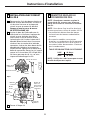
ANTI-TIP DEVICE
WARNING — To reduce the risk
of tipping, the appliance must be secured by
properly installed Anti-Tip bracket packed
with this appliance.
To check if the bracket is installed and
engaged properly, carefully tip the range
forward. The anti-tip bracket should engage
and prevent the range from tipping over.
WARNING —
• All ranges can tip
• Injury to persons could result
• Install Anti-Tip bracket packed
with range
• See Installation Instructions
If you pull the range out and away from the
wall for any reason, make sure the Anti-Tip
bracket is engaged when the range is pushed
back against the wall.
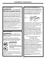
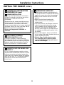
ELECTRICAL REQUIREMENTS
This appliance must be supplied with the
proper voltage and frequency and connected
to an individual, properly grounded branch
circuit, protected by a circuit breaker or fuse
having amperage as noted on the rating
plate. (Rating plate is located above the
storage drawer below the oven frame.)
We recommend you have the electrical wiring
and hookup of your range connected by a
qualified electrician. After installation, have
the electrician show you where your main
range disconnect is located.
Check with your local utilities for electrical
codes which apply in your area. Failure to
wire your range according to governing
codes could result in a hazardous condition.
If there are no codes, your range must be
wired and fused to meet the requirements of
the National Electrical Code, ANSI/NFPA No.
70–Latest edition. You can get a copy by
writing:
National Fire Protection Association
Batterymarch Park
Quincy, MA 02269
Effective January 1, 1996, the National
Electrical Code requires that new, but not
existing, construction utilize a four-conductor
connection to an electric range. When
installing an electric range in new
construction, a mobile home, recreational
vehicle or an area where local codes prohibit
grounding through the neutral conductor,
follow the instructions in the section on NEW
CONSTRUCTION AND FOUR-CONDUCTOR
BRANCH CIRCUIT CONNECTION.
In Canada your range must be wired
and fused to meet the requirements of the
Canadian Electrical Code.
You must use a three-wire, single-phase
A.C. 208Y/120 Volt or 240/120 Volt, 60 hertz
electrical system.
FOR YOUR SAFETY:
WARNING — For personal safety,
remove house fuse or open circuit breaker
before beginning installation. Failure to do so
could result in serious injury or even death.
All rough-in and spacing dimensions must be
met for safe use of your range. Electricity to
the range can be disconnected at the outlet
without moving the range if the outlet is in
the preferred location (remove lower drawer).
To reduce the risk of burns or fire when
reaching over hot surface elements, cabinet
storage space above the cooktop should be
avoided. If cabinet storage space is to be
provided above the cooktop, the risk can be
reduced by installing a range hood that sticks
out at least 5” beyond the front of the
cabinets. Cabinets installed above a cooktop
must be no deeper than 13”.
Be sure your appliance is properly installed
and grounded by a qualified technician.
Rating
plate location

4
Installation Instructions
INSPECT INSTALLATION
LOCATION
Refer to alternate construction section for
the following non-standard installations.
Counter opening extends to the wall:
Maintop Filler (supplied with the
range.) (See page 15 for Installation
Instructions) or
Backguard (Kit JXS36XX or JXS39SS).
Counter height greater than 36-3/4″:
Lower Trim Slide-In (Kit JXS56XX).
One side is not enclosed by a cabinet:
Bodyside (Kit JXS76XX).
Island Installation:
To provide an optimum installation, the
top surface of the countertop must be
level and flat (lie on the same plane)
around the 3 sides that are adjacent to
range cooktop. Proper adjustments to
make the top flat should be made or
gaps between the countertop and
range cooktop may occur. Forcing the
cooktop to fit may cause excessive
gaps and could break the glass and
void the warranty.
To obtain Kits:
a. Visit GE Web Site (See page 1)
b. Call GE Answer Center (See page 1)
c. Contact Dealer
D
C
B
A
1
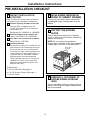
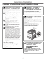
PRE-INSTALLATION CHECKLIST
MOVE RANGE INDOORS IN
FRONT OF CABINET OPENING
Do not use hand trucks when moving the
unpackaged range. Cooktop glass may be
broken.
2
PROTECT THE KITCHEN
FLOOR
Flatten and place a piece of the shipping
carton in front of the installation location to
protect the flooring.
NOTE: Do not remove the protective
channel from the sides of the glass cooktop,
if applicable, until later in the installation.
3
CAREFULLY, TILT RANGE TO
ACCESS RANGE LEVELING
LEGS
Use an adjustable wrench to screw leveling
legs out so that glass support flanges clear
top of countertop.
4
Protective
Channel
ADJUST

5
Installation Instructions
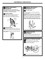
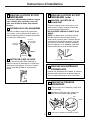
REMOVE THE DOOR IF
NECESSARY
(cont.)
LIFT OFF DOOR
Lift door up and out until the hinge arms
clear the slots.
DO NOT LIFT THE DOOR BY THE HANDLE.
NOTE: The oven door is very heavy. Be sure
you have a firm grip before lifting the oven
door off the hinges. Use caution once the
door is removed. Do not lay the door on its
handle. This could cause dents or scratches.
C
5
Hinge clears slot
REMOVE THE DOOR IF
NECESSARY
Door removal is not a requirement for
installation of the product, but is an added
convenience. To remove the door:
UNLOCK HINGES
Push both hinge locks down toward the
door frame, to the unlocked position.
This may require a flat blade screwdriver.
POSITION DOOR
Place hands on both sides of the door, and
close the oven door to the removal position.
This is half way between the broil stop and
fully closed.
B
A
5
REMOVE PACKING
MATERIALS
Also remove labels on door, plastic on trim
and panel and all tape around the range.
6
REMOVE STORAGE DRAWER
Pull the drawer out until it stops.
Lift the front of the drawer until the
stops clear the guides.
Pull forward and remove the drawer.
C
B
A
7
Rail
Guide
Stop
Stop
Hinge
slot
Hinge
unlocked
position
Hinge
arm

6
Installation Instructions
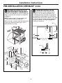
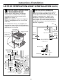
PRE-INSTALLATION CHECKLIST
(CONT.)
PRE-INSTALLATION CUTOUT
AND REQUIRED CLEARANCES
If cabinets are placed less than 30″ above the
range, see Alternate Construction, Step 25E,
on page 18.
NOTE: Product meets UL requirements for
0″ clearance to back and side walls.
Wall coverings, counters and cabinets around
range must withstand heat (up to 194°F)
generated by the range.
8
12
″
23-3/16
″
7
″
A
c
c
e
p
ta
b
le
G
a
s
L
in
e
&
E
le
c
tr
ic
a
l
O
u
tle
t A
r
e
a
3
0
″ M
in
.
3
0
″
M
in
.
fr
o
m
c
o
o
k
in
g
s
u
r
fa
c
e
to
b
o
tto
m
o
f o
v
e
r
h
e
a
d
c
a
b
in
e
ts
S
h
a
v
e
R
a
is
e
d
E
d
g
e
T
o
C
le
a
r 3
1
-1
/8
″
W
id
e
C
o
n
tro
l P
a
n
e
l
6
″
M
i
n
.
F
r
o
m
W
a
l
ls
1
3
″
M
a
x
.
d
e
p
th
For Optimum
Installation These
Surfaces Must
Be Flat & Level
F
o
llo
w
in
s
tru
c
tio
n
s
p
a
c
k
a
g
e
d
w
ith
a
lte
rn
a
te
a
p
p
l
ia
n
c
e
C
o
u
n
te
rto
p
D
e
p
th
2
5
″
(ty
p
ic
a
l)
35-3/4
″
to 36-1/2
″
from floor to
countertop
18
″
Min. vertical
distance from the
bottom of the adjacent
overhead cabinets
1-1/4
″
Min. Counter top
to top of drawer
D
raw
er
c
o
r
d
, p
lu
g
,
r
e
c
e
p
t
a
c
l
e
b
o
x
3
.5
″
to
p
r
e
v
e
n
t
in
te
r
fe
r
e
n
c
e
&
g
a
s
h
o
o
k
u
p
Max. depth of
with drawer
9
/1
6
″
29-15/16"Min.
30-1/16" Max.
29-15/16
″
Min.
30-1/16
″
Max.
3
″
15
″
STANDARD INSTALLATION
If the construction of your cabinet cannot
provide a 1/4″ flat area at the back of the
countertop opening, consider changing the
countertop to accommodate this dimension.
See Alternate Construction section. If the area
is not flat, excess tension may be applied to
the glass cooktop, causing breakage and
voiding the warranty.
9
1/4″ min.
flat
9/16″
min.
flat
29-15/16″–30-1/16″
smooth cut
23-3/16″
25″
typically
Wall
Flat area
R
1/4″
9/16″
min.
flat
36″

7
Installation Instructions
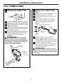
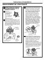
MAKING THE CONNECTIONS
(cont.)
Install 1/2″ flare union adaptor to the 1/2″
NPT elbow on pressure regulator.
Connect flexible appliance connector to
flare union.
Move range into approximate position
and connect flexible connector to gas
supply line with proper flare union
adaptor.
To prevent gas leaks, put a pipe joint
sealant or Teflon
®
tape on all male
threads. NOTE: Make sure sealant or tape
is compatible with Natural and LP gases.
When you are finished making
connections, be sure that all range knobs
are turned to OFF before you open the
main gas supply valve.
WARNING:
Do not use a flame
to check for gas leaks. Use liquid leak detector
at all joints and connections to check for leaks
in the system.
I
H
G
F
E
10
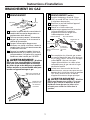
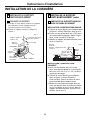
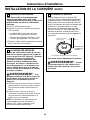
GAS CONNECTIONS
MAKING THE CONNECTIONS
Install a manual shut-off valve in the gas
supply line in an easily accessible location.
Know how and where to shut off the gas
supply to the range.
Shut off gas supply before removing an
old range. Leave it off until hookup of
new range is finished.
Because solid pipe restricts moving the
range, we recommend use of a C.S.A.
certified flexible metal appliance
connector.
WARNING:
Never reuse old
flexible connectors. The use of old flexible
connectors can cause gas leaks and personal
injury. Always use new flexible connectors
when installing a gas appliance.
D
C
B
A
10
3″
15″
12″
3
1
⁄2″
7″
Gas Inlet
Gas supply to
top burner
Pressure
regulator as
seen from
front of range
Pressure
regulator
Gas
supply
line
90° street
elbow
Shut-off valve Flexible gas line
7″ Max.

8
Installation Instructions
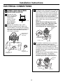
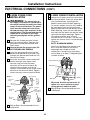
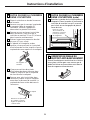
ELECTRICAL CONNECTIONS
POWER CORD AND STRAIN
RELIEF INSTALLATION
Remove the wire
cover (on the back
of the range) by
removing 2
screws, using a
1/4″ nut driver.
Do not discard
these screws.
Remove the knockout ring (1-3/8″)
located on bracket directly below the
terminal block. To remove the knockout,
use a pair of pliers to bend the knockout
ring away from the bracket and twist
until ring is removed.
B
A
11
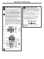
For power cord installations only (see the
next step if using conduit), assemble the
strain relief in the hole. Insert the power
cord through the strain relief and tighten.
Allow enough slack to easily attach the
cord terminals to the terminal block. If
tabs are present at the end of the winged
strain relief, they can be removed for
better fit.
NOTE: Do not install the power cord
without a strain relief. The strain relief
bracket should be installed before
reinstalling the rear range wiring cover.
For conduit installations only, purchase
a squeeze connector matching the
diameter of your conduit and assemble it
in the hole. Insert the conduit through
the squeeze connector and tighten. Allow
enough slack to easily attach the wires to
the terminal block.
NOTE: Do not install the conduit without
a squeeze connector. The squeeze
connector should be installed before
reinstalling the rear range wiring cover.
D
C
Wire Cover
Terminal block
(appearance
may vary)
Knockout
ring removed
Knockout ring
in bracket
Terminal
block
Bracket
Terminal
block
Strain relief
Power cord
Bracket
Squeeze
connector
Conduit

9
Installation Instructions
NEW CONSTRUCTION AND
FOUR-CONDUCTOR BRANCH
CIRCUIT
All New Constructions, Mobile
Homes, Recreational Vehicles
and Installations Where Local
Codes Do Not Allow Grounding
Through Neutral Must Use the
4-Wire Cord Provided
FOR EXISTING
CONSTRUCTION,
A THREE-WIRE FLEXIBLE
CORD KIT MAY BE USED
Follow instructions in step
14 if you require a 3-wire
cord:
13
12
3-WIRE POWER CORD
INSTALLATION
WARNING: The neutral or ground
wire of the power cord must be
connected to the neutral terminal
located in the center of the terminal
block. The power leads must be
connected to the lower left and the
lower right terminals of the terminal
block.
Remove the 3 lower terminal screws
from the terminal block. Insert the 3
terminal screws through each power
cord terminal ring and into the lower
terminals of the terminal block. Be
certain that the center wire
(white/neutral) is connected to the center
lower position of the terminal block.
Tighten screws securely into the terminal
block.
DO NOT remove the ground strap
connection.
Skip to Step 18 and proceed with the
installation.
B
A
14
NEMA 14-50R
4-wire
208/240 40 Amp
3-prong cord
Terminal block
(appearance
may vary)
Ground
plate
Power cord
Ground
strap
Neutral
terminal

ELECTRICAL CONNECTIONS (CONT.)
3-WIRE CONDUIT INSTALLATION
Loosen the 3 lower terminal screws from
the terminal block. Insert the center bare
wire (white/neutral) tip through the
bottom center terminal block opening.
On certain models, the wire will need to
be inserted through the ground strap
opening and then into the bottom center
block opening. Insert the two side bare
wire tips into the lower left and the lower
right terminal block openings. Tighten
the screws until the wire is firmly
secured (35 to 50 inch-lbs.). Do not over-
tighten the screws since it could damage
the wires.
NOTE: ALUMINUM WIRING:
Aluminum building wire may be used
but it must be rated for the correct
amperage and voltage to make
connection. Connect wires according
to this Step 16 or Step 17 depending on
number of wires.
Wire used, location and enclosure of
splices, etc., must conform to good
wiring practices and local codes.
Skip to Step 18 and proceed with the
installation.
B
A
16
10
Installation Instructions
4-WIRE POWER CORD
INSTALLATION
WARNING: The neutral wire of
the supply circuit must be connected to
the neutral terminal located in the lower
center of the terminal block. The power
leads must be connected to the lower
left and the lower right terminals of the
terminal block. The ground lead must be
connected to the frame of the range
with the ground plate and the ground
screw.
Remove the 3 lower terminal screws
from the terminal block. Remove the
ground screw and ground plate and
retain them.
Cut and discard the ground strap. DO
NOT DISCARD ANY SCREWS.
Insert the one ground screw into the
power cord ground wire terminal ring,
through the ground plate and into the
frame of the range.
Insert the 3 terminal screws (removed
earlier) through each power cord
terminal ring and into the lower
terminals of the terminal block. Be
certain that the center wire (white/
neutral) is connected to the center lower
position of the terminal block. Tighten
screws securely into the terminal block.
Skip to Step 18 and proceed with the
installation.
E
D
C
B
A
15
or
Terminal
block
Ground strap
Ground
strap
Neutral
terminal
Before
After
Terminal
block
Ground
screw
Ground
plate
(grounding
to range)
Bracket
Conduit
Wire tips
Terminal block

11
Installation Instructions
REINSTALL WIRE COVER.
NOTE: When reinstalling the wire cover,
make sure that wires do not become pinched
between the wire cover and the housing.
NOTE: The ground strap must be attached
when using the 3-wire cord.
• Terminations must be either closed loop
terminals or open-end spade lugs.
• On some models, a filter capacitor may
be connected between the black and
ground leads on the junction block.
Do not remove capacitor.
BREAKER OR FUSE SIZE
240V 40 Amps
208V 40 Amps
NOTE: Check Local Codes for required
breaker size.
18
4-WIRE CONDUIT INSTALLATION
Loosen the three lower terminal screws
from the terminal block. Remove the
ground screw and ground plate and
retain them. Cut and discard the ground
strap. DO NOT DISCARD ANY SCREWS.
Insert the ground bare wire tip between
the range frame and the ground plate
(removed earlier) and secure it in place
with the ground screw (removed earlier).
Insert the bare wire (white/neutral) tip
through the bottom center of the
terminal block opening. Insert the two
side bare wire tips into the lower left and
the lower right terminal block openings.
Tighten the screws until the wire is firmly
secured (35 to 50 inch-lbs.). Do not over-
tighten the screws since it could damage
the wires.
Proceed to Step 18.
C
B
A
17
or
Terminal
block
Ground strap
Neutral
terminal
Ground strap
Before
Terminal
block
Wire tips
Ground
screw
Bracket
Ground
plate
(grounding
to range)
After

12
Installation Instructions
INSTALL THE ANTI-TIP BRACKET
LOCATE THE BRACKET
a. Decide whether the bracket will be
installed on the right or left side of the
range opening.
b. Place the bracket as shown in Fig. 1.
A
19
Rear
leveling leg
Wall
FLOOR-CONCRETE
INSTALL THE RANGE
INSTALL THE ANTI-TIP BRACKET
(cont.)
INSTALL THE BRACKET IN WOOD OR
CONCRETE
INSTALLATION—WOOD CONSTRUCTIONS
a. Locate the centers of the 4 holes identified
in Fig. 1 as Floor–Wood and Wall.
b. Drill a 1/8″ pilot hole through the
pre-marked areas. Note the angle of the
wall screw in Fig. 2.
c. Mount the Anti-Tip bracket with the
4 screws provided.
INSTALLATION—CONCRETE CONSTRUCTIONS
a. For concrete installation, you will need
two 1/4″ x 1-1/2″ lag screws and two sleeve
anchors.
b. Locate the center of the 4 holes identified
in Fig. 1 as Floor–Concrete and Wall. Drill
the recommended size holes in each.
c. Install the sleeve anchors into the
predrilled concrete holes and install the
lag and wall screws through the Anti-Tip
bracket. Make sure the screws are securely
tightened.
B
19
FLOOR-WOOD
Bracket
side
Adjacent
cabinet
Top front
edge of
countertop
25″
Wall plate
Screw
must enter
wood or
metal
Bracket
Fig. 1
Fig. 2

13
Installation Instructions
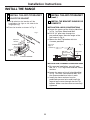
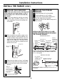
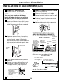
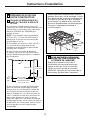
SLIDE RANGE INTO OPENING
Position the range in front of the cabinet
opening.
Make sure that the glass which overhangs
the countertop clears the countertop.
If necessary, raise the unit by lowering
the leveling legs.
Push while lifting the range into the
opening, until the range is within 2″
of engaging the anti-tip bracket.
Remove the protective trim from the side
of glass (if provided).
Using the adjustable pliers or wrench,
carefully screw in the back leveling leg
until the glass overhang comes to rest
on the countertop.
Carefully screw in the front two leveling
legs (similar to Step E) until the glass
overhang touches the countertop.
Carefully push the range into the opening
until the countertop fully engages the
control panel. The back glass overhang
should cover the cutout opening.
G
F
E
D
C
B
A
20
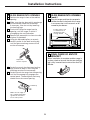
SLIDE RANGE INTO OPENING
(cont.)
Plug the range cord into the receptacle.
Locate the cord in the back of the range
in a manner that it will not touch or be
moved by the drawer.
H
20
STORAGE DRAWER
Position range cord
so that there is no
interference with
storage drawer
Adjustable
wrench or pliers
Countertop
Make sure the edge of
the countertop fits flush
against the end of the
front control panel
FINAL CHECK OF ANTI-TIP
BRACKET
When installation is complete and the range is
in place, check to be sure that the rear leveling
leg is fully inserted into the slot of the Anti-Tip
Bracket.
21

INSTALL THE RANGE
(CONT.)
14
Installation Instructions
REPLACE THE OVEN DOOR
NOTE: The oven door is heavy. You may need
help lifting the door high enough to slide it
into the hinge slots. Do not lift the door by
the handle.
Lift the oven door by placing one hand
on each side. The door is heavy, so you
may need help. Do not lift the door by
the handle.
With the door at the same angle as the
removal position (halfway between the
closed and broil stop position), seat the
notch of the hinge arm into the bottom
edge of the hinge slot. The notch of the
hinge arm must be fully seated into the
bottom of the slot.
Open the oven door as far as it will open.
Push the hinge locks up against the front
frame of the oven cavity, to the locked
position.
Close the oven door.
E
D
C
B
A
22
REPLACE THE STORAGE
DRAWER
Place the drawer rail on the guides.
Push the drawer in until it stops.
Lift the front of the drawer and push in
until the stops clear the guides.
Lower the front of the drawer and push in
until it closes.
SPECIAL INSTRUCTIONS IF YOU ARE
HAVING PROBLEMS WHILE REPLACING
THE STORAGE DRAWER
Remove and replace, making sure the power
cord is not obstructing the drawer and/or the
rail is in the guide.
Remove and replace, making sure the rail is in
the guide.
D
C
B
A
23
Stop
Bottom edge
of slot
Hinge in
locked position
Notch of hinge
securely fitted
into bottom of
hinge slot
Drawer does
not close
completely
Drawer
front panel
tipped away
from body
side
Rear drawer
support is on top
of guide rail on
the high side
Drawer front panel
tipped to one side
Hinge arm
Hinge notch
If Drawer Won’t Close:
If Drawer is Crooked:
Power cord
may be
obstructing
drawer
in this area
Rear drawer
support is
resting on top
of guide rail

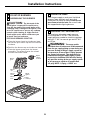
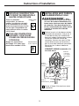
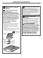
COOKTOP BURNERS
ASSEMBLING THE BURNERS
CAUTION: The electrode of the
spark igniter is exposed. Be careful not to
snag the electrode of the spark igniter with
a cleaning cloth. Damage to the igniter could
occur. Be careful not to turn on any cooktop
controls while cleaning. A slight electrical
shock might result, which could cause you
to knock over hot cookware.
FOR GLASS CERAMIC COOKTOPS
a. Place the burner head on the burner base,
so that the pins match up with the slots on
the base.
b. Position the burner cap on the burner head.
c. Place the burner grate over the burner
assembly. The grates fit over the raised
area on the burner head.
A
24
Burner
grate
Burner
base
Burner
cap
Burner
head
Spark
igniter
Glass
maintop
15
Installation Instructions
CHECK FOR LEAKS
Turn the gas supply on and use a liquid leak
detector (soap solution) at all joints and
connections to check for leaks. Do not use an
open flame to look for leaks. Be sure all leaks
are stopped before lighting burners.
B
PRESSURE TEST INFORMATION
The maximum allowable supply pressure
for the regulator is 14″ W.C. The minimum
supply pressure needed to check the regulator
setting is 7″ W.C. for natural gas and 10″ W.C.
for LP gas.
WARNING: The range and its
individual shut-off valve must be disconnected
from the gas supply piping system during any
pressure testing of the gas supply system at
test pressures of more than 1/2 psig (pounds
per square inch gauge). The range must be
isolated from the gas supply piping system
by closing its individual shut-off valve during
any pressure testing of the gas supply system
at test pressures equal to or greater than
1/2 psig. NOTE: 1/2 psig = 13.855″ w.c.
C
Spark
igniter
location

INSTALL THE RANGE
(CONT.)
16
Installation Instructions
CHECK THE IGNITERS
Operation of the electric igniters should be
checked after the cooktop and supply line
have been carefully checked for leaks and the
cooktop has been connected to the electrical
power.
a. Turn on gas.
b. Push and turn a burner valve to the LITE
position.
• The burner valve should light when gas
is available to the burner.
• Once the burner lights, it should be
turned out of the LITE position.
c. Try each valve separately until all burners
have been checked.
D
BURNER IGNITION
Cooktop Spark Ignition—When you turn
the cooktop knob to LITE, the spark igniter
makes a series of electric sparks (ticking
sounds) which light the burner. During a
power failure the burners will not light
automatically. In an emergency, a cooktop
burner may be lit with a match by following
the steps below.
WARNING: Lighting gas burners
with a match is dangerous. You should match
light the cooktop burners only in an
emergency.
a. Light a match and hold the flame near the
burner you want to light. Wooden matches
work best.
b. Push in and turn the control knob slowly.
Be sure you are turning the correct knob
for the burner you are lighting.
NOTE: If the burner does not light within
five seconds, turn the knob off and wait
5 minutes before trying again.
E
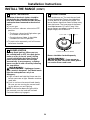
BURNER FLAMES
Turn each burner on. Turn each burner knob
to the high position. Flames should be blue
in color with no or little trace of yellow. The
burner flames should not flutter or blow away
from the burner. The inner cone of the flame
should be between 1/2″ to 3/4″ long. If the
burner flames are yellow in color or not the
proper length, call GE Service.
Burners should be checked frequently.
WARNING:
If you attempt to
measure the inner cone of the flame, please
use caution. Burns could result.
F
1/2″ to 3/4″
COOKTOP
BURNER
Flames should circle burner

17
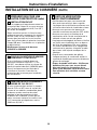
Installation Instructions
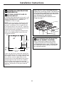
ALTERNATE CONSTRUCTION
PREPARATION
OPTIONAL MAINTOP FILLER OR
BACKGUARD KIT
If counter opening extends to the wall, it will
require Maintop Filler Kit (supplied with the
range) or Backguard Kit (JXS36XX or
JXS39SS) to close the gap.
NOTE: If the countertop is greater than 25″,
it will show a gap between the backguard
and wall or between filler kit and the wall.
If the countertop is less than 25″, a gap will
occur between the countertop front and the
control panel ends (see Step 8).
If you are using the optional backguard kit,
refer to the backguard kit instructions for
installation details.
If you use the filler kit, place the metal filler
piece supplied with the range to the back of
the range as shown in the figure below. Start
the 2 screws into the upper holes at the
outside rear of the range above the louvers
and through the slots in the trim, holding
the filler piece centered on the maintop
frame and pushing upward to close the gap
between the bottom of the glass and the
filler trim.
A
25
When the trim is set in the proper position,
tighten the 2 mounting screws. The top of the
trim should be located below the top surface
of the glass to prevent pots, pans and skillets
from damaging the painted parts.
Refer to the Standard Installation of the
Range on page 6.
Wall
25″
Must be
level
Must be
flat
30″
smooth cut
Must be level
31-1/8″
Must
be
flat
(2) #8
screws
Maintop filler
Range
Cooktop
FOR NON-BUILT-IN INSTALLATION
(END OF CABINET LOCATION)
When installing the range at the end of
a cabinet section which will expose the
unfinished side of the range, use Body Side
Kit (JXS76XX). Refer to the kit instructions
for installation details.
B

INSTALL THE RANGE
(CONT.)
18
Installation Instructions
ALTERNATE CONSTRUCTION
PREPARATION (cont.)
ISLAND INSTALLATION
Attach the Anti-Tip bracket per instructions
in Step 19, making sure that the rear of the
bracket is 25″ from the front of the
countertop.
Be aware that the screws provided are long
and may penetrate through the back of the
island cabinets. In this event, use shorter
screws (not provided) or the screws provided
should be used in the floor (see Step 19B for
Wood/Concrete Floor Installation).
Do not use Backguard Kit JXS36XX or
JXS39SS.
C
25
FOR CABINET OPENINGS
APPROXIMATELY 30-3/8″
If range is installed in cabinet opening
approximately 30-3/8″, the Vertical Side Trim
Kit (JXS86XX) should be used to cover gaps
between range sides and cabinet. Refer to
the kit instructions for installation details.
D
CABINETS OVER THE RANGE LESS
THAN 30″
If a 30″ clearance between cooking surface
and overhead combustible material or metal
cabinets cannot be maintained, protect the
underside of the cabinets above the cooktop
with not less than 1/4″ insulating millboard
covered with sheet metal not less than
0.0122″ thick.
E
OPERATION CHECKLIST
• Double check to make sure everything in
this guide has been completed. Rechecking
steps will ensure safe use of the cooktop.
• Make sure all controls are left in the OFF
position.
• Make sure the flow of combustion
and ventilation air to the cooktop is
unobstructed.
• The serial plate for your Range is located
under the oven door above the storage
area. In addition to the model and serial
numbers, it tells you the ratings of the
burners and the type of fuel and pressure
the cooktop was adjusted for when it left
the factory.
• When ordering parts, always include the
serial number and model number to ensure
proper replacement parts.
• Recheck Steps: Double check to make
sure everything in this guide has been
completed. Rechecking steps will ensure
safe use of the Range.
26

19
Installation Instructions
IN SOME CASES
With L.P. gas, some yellow tipping on
the outer cone is normal.
Foreign particles in the gas line may
cause an orange flame at first, but this
will soon disappear.
SPECIAL NOTE:
To convert the oven back to natural gas,
reverse the instructions given in making L.P.
Adjustments.
Once the conversion is complete
and checked ok, fill out the LP
sticker and include your name,
organization and the date the
conversion was made. Apply the sticker near
the regulator to alert others in the future that
this appliance has been converted to LP gas.
If converting back to natural gas from LP,
please remove the sticker so others know
the appliance is set to use natural gas.
B
A
Please see L.P. conversion instructions
supplied with this range when L.P. Gas
is used.
NOTE: Instructions are mounted on
regulator bracket.
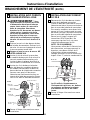
ADJUSTING LOW FLAME SETTING
ON COOKTOP BURNERS
Low setting adjustments must be made with
two other burners in operation on a medium
setting. This procedure prevents the low
flame from being set too low, resulting in the
flame being extinguished when other burners
are turned on.
Remove the valve control knobs.
Through the opening, locate the valve
bypass screw located on the lower right
side of the valves.
Using a small screwdriver, screw down
the bypass screw fully in a clockwise
rotation.
C
B
A

20
Printed in the United States
La page est en cours de chargement...
La page est en cours de chargement...
La page est en cours de chargement...
La page est en cours de chargement...
La page est en cours de chargement...
La page est en cours de chargement...
La page est en cours de chargement...
La page est en cours de chargement...
La page est en cours de chargement...
La page est en cours de chargement...
La page est en cours de chargement...
La page est en cours de chargement...
La page est en cours de chargement...
La page est en cours de chargement...
La page est en cours de chargement...
La page est en cours de chargement...
La page est en cours de chargement...
La page est en cours de chargement...
La page est en cours de chargement...
La page est en cours de chargement...
-
 1
1
-
 2
2
-
 3
3
-
 4
4
-
 5
5
-
 6
6
-
 7
7
-
 8
8
-
 9
9
-
 10
10
-
 11
11
-
 12
12
-
 13
13
-
 14
14
-
 15
15
-
 16
16
-
 17
17
-
 18
18
-
 19
19
-
 20
20
-
 21
21
-
 22
22
-
 23
23
-
 24
24
-
 25
25
-
 26
26
-
 27
27
-
 28
28
-
 29
29
-
 30
30
-
 31
31
-
 32
32
-
 33
33
-
 34
34
-
 35
35
-
 36
36
-
 37
37
-
 38
38
-
 39
39
-
 40
40


GE J2S968BEKBB Guide d'installation
- Catégorie
- Cuisinières
- Taper
- Guide d'installation
- Ce manuel convient également à
dans d''autres langues
- English: GE J2S968BEKBB Installation guide