Genie 6172H-B Mode d'emploi
- Catégorie
- Porte de garage
- Taper
- Mode d'emploi

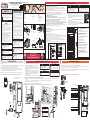
1) CLOSE DOOR.
2) Notate mounting bracket orientation and remove bolt and lock washer (A) from powerhead chassis and loosely install
mounting bracket from kit bag on desired side of powerhead. (Right Hand mount shown)
NOTE: Bracket can be mounted to opener on either side depending on mounting requirements.
3) Pull emergency release cable to disconnect opener to rotate output shaft for ease of coupler installation.
4) Slide coupler (1-1/4” end) onto opener output shaft until it fully seats. (See Coupler Cross Section detail below)
5) Tighten 3 inner set screws on coupler nger tight against opener output shaft.
NOTE: The coupler must be installed onto the opener output shaft until the coupler seats completely to the recess inside coupler.
NOTE: Opener MUST be mounted to garage framing material. DO NOT install to particle board or drywall.
Coupler Cross Section
Opener Output
Shaft - 1-1/4”
Door Shaft - 1”
A
Opener
Output
Shaft
Opener
Mounting
Bracket
7/16”
SOCKET
1. Carefully inspect the counterbalance lift cables on the door. If they are worn,
frayed or broken, contact a qualied door service company to replace the
counterbalance lift cables before installing the cable keepers.
2. Push spacer onto the shaft between the short stem track roller and the bottom
corner bracket. Use an additional spacer if needed to achieve a minimum of
1/2” clearance FIG-1.
3. If there is less than 1/2” clearance, loosen the lag screws attaching the track to
the wall and adjust the track for the 1/2” clearance. Re-tighten the lag screws.
4. Position the right hand (black) cable keeper assembly directly above the
garage door bottom corner bracket. WARNING - DO NOT loosen or remove
bottom corner bracket screws.
5. The cable keeper assembly must extend 1/8” past the end of the door section. Ensure there is no more than 4-1/2” from the bottom edge of the door to bottom of cable keeper FIG.2.
IMPORTANT: RIGHT AND LEFT HAND IS ALWAYS DETERMINED FROM INSIDE THE BUILDING LOOKING OUT.
6. Fasten the cable keeper assembly with (2) 1/4” - 22 x 11/16” self drilling screws (wood doors will use (2) 1/4” x 1” lag screws). Once the cable keeper assembly is secured to the bottom
section FIG. 3.
7. Place the plastic sleeve over the counterbalance lift cable and then rotate the cable keeper arm upward and attach it to the plastic sleeve FIG. 4.
8. Repeat the same process for the left hand (Red) cable keeper assembly.
NOTE: It is recommended that wood doors be pre-drilled with 1/8” pilot holes prior to fastening.
IMPORTANT NOTE: Operate door manually full open to full close and watch keeper to ensure that it does not contact door track. Adjust as necessary.
1/8”
1/2” Min
4-1/2” Max
FLOOR
Cable Keeper
Assembly
Cable Keeper Arm
(2) 1/4” -20 x 11/16”
Self Drilling Screws
Counterbalance
lift cable
Cable
keeper arm
Cable keeper
assembly
installed
Plastic
sleeve
Plastic
sleeve
Counterbalance
lift cable
1) Mount opener to door shaft.
• If the door shaft is NOT keyed, slide opener assembly onto door shaft and tighten setscrews nger tight.
• If the door shaft IS keyed, insert provided key into either keyway. Pull emergency release cable at the bottom of the opener to allow free rotation of the
output shaft to “clock” the keyways together. Tighten set screws onto door shaft nger tight.
NOTE: The mounting of this opener to the door shaft is designed so the door shaft will slide through the coupler and enter the hollow output shaft of the opener
up to 3 -3/8” (there is a stop pin located in the center of the opener output shaft).
DOOR
RELEASE CABLE
SOLID OR HOLLOW
DOOR SHAFT NO KEY
SOLID KEYED
DOOR SHAFT
OPENER REMOVED FOR CLARITY, RIGHT HAND INSTALL SHOWN
Bracket can be mounted
to opener on either side
depending on mounting
requirements.
ASSEMBLE OPENER
1INSTALL CABLE KEEPERS ON DOOR
2INSTALLING THE OPENER (CONT’)
3
NOTE: Coupler may include square head
or 6 point head screws.
41415.00188, 06/2020
Assembly & Installation Video
Available at: www.GenieCompany.com
or scan this code
WALL MOUNT OPENER ASSEMBLY &
INSTALLATION INSTRUCTIONS
IMPORTANT INSTALLATION
INSTRUCTIONS
POTENTIAL HAZARDS
Overhead doors are large, heavy objects that move with the help of springs under high tension and electric motors. Since moving objects,
springs under tension, and electric motors can cause injuries, your safety and the safety of others depends on you reading the information in
this installation poster. If you have questions or do not understand the information presented, call The Genie Company (1-800-35-Genie). In
this section, and those that follow, the words Danger, Warning and Caution are used to emphasize important safety information.
Indicates an imminently hazardous situation which, if not avoided, will result in death or serious injury.
Indicates a potentially hazardous situation which, if not avoided, could result in death or serious injury.
Indicates a potentially hazardous situation which, if not avoided, may result in injury or property damage.
NOTE
is used to indicate important steps to be followed or important considerations.
WARNING
CAUTION
DANGER
!
!
!
TO REDUCE THE RISK OF SEVERE INJURY
OR DEATH
READ AND FOLLOW ALL SAFETY, INSTALLATION AND OPERATION INSTRUCTIONS. If you have
any questions or do not understand an instruction, call The Genie® Company or your local
Genie® Factory Authorized Dealer.
• DO NOT install opener on an improperly balanced door. An improperly balanced door
could cause severe injury. Repairs and adjustments to cables, spring assembly, and other
hardware must be made by a trained service person using proper tools and instructions.
•
Remove all pull ropes and remove or disable all locks connected to the garage door before
installing opener.
• Where possible, install door opener 7 ft. (2.14M) or more above the floor. For products
having an emergency release, mount the emergency release within reach, but at least 6 ft.
(1.83m) above the floor to prevent children from reaching it.
• DO NOT connect the opener to the source of power until instructed to do so.
• Locate the wall console button: A) Within sight of door. B) At a minimum height of 5 feet
so small children cannot reach it. C) Away from all moving parts of the door.
• Install the entrapment WARNING label next to the wall button or console. Install red
emergency release handle on the emergency release cord.
• The opener must reverse when the door contacts a 1-1/2 in. (38mm) high object on the
floor at the center of the doorway. This is about the size of a 2" x 4" board laid flat.
• For products having a manual release, instruct the end user on the operation of the
manual release.
WARNING
!
WARNING
!
A moving door could result in serious injury or death.
•Keeppeopleclearofopeningwhiledoorismoving.
•DO NOT allow children to play with the door opener.
•DO NOT operate a door that jams or one that has a broken spring.
WARNING
!
An Electrical Shock could result in serious injury or death.
•Turnoffpowerbeforeremovingopenercover.
•Whenreplacingcover,makesureelectricalwiresarenotpinchedornearmovingparts.
•Openermustbeproperlygrounded.
WARNING
!
WARNINGHIGH SPRING TENSION
•DO NOT try to remove, repair or adjust springs or anything to which door spring parts are fastened, such as wood
block, steel brackets, cables or other like items.
•Repairsandadjustmentsmustbemadebyatraineddoorsystemtechnicianusingpropertoolsandinstructions.
POUR RÉDUIRE LES RISQUES DE
BLESSURES GRAVES VOIRE MORTELLES
LIRE ET SUIVRE ATTENTIVEMENT TOUTES LES INSTRUCTIONS D’INSTALLATION ET
DE FONCTIONNEMENT AINSI QUE TOUTES LES CONSIGNES DE SÉCURITÉ. Si vous
avez des questions ou si vous ne comprenez pas une instruction, veuillez contacter
directement The
Genie Company.
• NE PAS installer l’opérateur sur une porte mal équilibrée. Celle-ci
pourrait entraîner de graves blessures. Les réparations et les réglages
des câbles, ensembles de ressort ou tout autre article de quincaillerie
doivent être eectués par un professionnel qui se sert d’outils appro-
priés et qui respecte les instructions.
• Enlever toutes les cordes et désactiver toutes les verrous de la porte
avant l’installer l’opérateur.
• Dans la mesure du possible, installer l’ouvre-porte à 2,1 m ou plus
au-dessus du sol. Pour les produits dotés d’un cordon de déclenche-
ment d’urgence, installer le déclenchement d’urgence mais au moins
à 1,8 m au-dessus du sol en évitant tout contact avec les véhicules
pour éviter qu’ils ne soient déclenchés accidentellement. NE PAS utili-
ser d’urgence cordon de libération pour ouvrir ou fermer la porte.
• NE PAS connecter l’opérateur à la source d’alimentation tant que
l’instruction n’est pas donnée.
• Repérer la console murale: A) En vue de la porte. B) À une hauteur mi-
nimale de 1,5 m an que les jeunes enfants ne puissent pas l’atteindre.
C) Loin de toutes pièces mobiles de la porte du garage.
• Placer l’étiquette d’AVERTISSEMENT en cas de coinçage à proximité du
bouton mural ou de la console de manière à ce qu’elle soit bien en évi-
dence. Installer la poignée du cordon de déclenchement d’urgence.
• L’opérateur doit s’inverser lorsque la porte entre en contact avec un
objet d’une hauteur de 3,8 cm placé sur le sol, au centre de l’ouverture
de la porte. Ceci équivaut environ à une planche de 5 x 10 cm posée à
plat sur le sol.
• Pour les produits à libération manuelle, informez l’utilisateur nal sur
le fonctionnement de la libération manuelle
AVERTISSEMENT
!
AVERTISSEMENT
!
CHOC ÉLECTRIQUE POURRAIT ENTRAÎNER DES BLESSURES GRAVES VOIRE
LA MORT
• Couper le courant avant d’enlever le couvercle de l’opérateur.
• Lorsque le couvercle doit être remplacé, s’assurer que les ls ne sont ni coincés ni près des pièces
mobiles.
• L’opérateur doit être correctement mis à la terre.
AVERTISSEMENT
!
TENSION ÉLEVÉE RESSORT POURRAIT ENTRAÎNER DES BLESSURES
GRAVES VOIRE LA MORT
• Ne pas essayer d’enlever, réparer ni ajuster les ressorts ou toute autre pièce à laquelle le ressort
de la porte est attaché, y compris blocs de bois, supports en acier, câbles ou autres articles
semblables.
• Les réparations et les réglages doivent être eectués par technicien qualié qui se sert d’outils
appropriés et qui respecte les instructions.
AVERTISSEMENT
!
PORTE EN MOUVEMENT POURRAIT ENTRAÎNER DES BLESSURES GRAVES
VOIRE LA MORT
• Utiliser uniquement si la porte est en vue et libre de tout obstacle. Ne laisser personne se tenir
dans l’ouverture de la porte pendant qu’elle est en mouvement.
• Ne pas permettre aux enfants de jouer avec l’opérateur de la porte.
• Ne pas modier la commande de l’opérateur à contact momentané à moins qu’un moyen
d’inversion externe soit installé.
• Ne pas faire fonctionner une porte qui bloque ou dont le ressort est cassé.
RECOMMENDED TOOLS
Ladder
Safety Glasses
Drill
-1/4” bit
-3/32” bit
Socket Set
-7/16”
-1/2”
Assorted Wrenches
-7/16”
-1/2”
Pencil
Tape Measure
Spirit Level
Wire Cutters/Strippers
Small Common Screwdriver
Common Screwdriver
Phillips Head Screwdriver
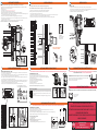
IMPORTANT PRE-INSTALLATION CONSIDERATIONS
Critical Measurements:
This opener can be installed left or right handed.
Critical measurements must be taken to ensure this opener will t the intended door.
This opener will directly couple onto torsion shafts, solid or tubular, of 1 inch in diameter with or without a keyway. (X)
Measure the distance between the torsion bar centerline to the wall. This dimension must be between 2-1/2” and 6”. (A)
The torsion bar shaft must protrude no less than 2-1/4” from bearing plate. (B)
A standard 115 VAC grounded electrical outlet will be required within 6 feet of the bottom of the opener.
Torsion bar centerline to the ceiling must be at least 2-1/4” for clearance. (C) NOTE: Headroom required is less than
smallest standard drum (400.8).
End of torsion shaft to side wall clearance must be at least 7 in. for clearance (D)
Important Compatibility Considerations:
Door Inspection:
If the intended door meets the above requirements, inspect the door for proper balance
and general condition.
• Raise and lower the door manually. Door should move freely and smoothly.
• Raise door manually about 3’ to 4’ feet from oor and let go.
Door should remain
stationary or slowly drift closed. FIG.A.
If door opens or closes rapidly, CONTACT A TRAINED DOOR SYSTEM TECHNICIAN to have your
door springs serviced.
• Disable or remove all locks and ropes attached to the door.
• Monitor the end of the torsion bar while the door is raised and lowered. It is important that
there is no noticeable movement up and down or side to side, if there is, CONTACT A TRAINED DOOR SYSTEM TECHNICIAN,
otherwise opener reliability will be signicantly reduced.
WARNING
Garage door hardware (springs, cables, brackets, pulleys, etc.) are under
extreme pressure and tension.
DO NOT attempt to repair or adjust door springs or any hardware, and
DO NOT OPERATE garage door automatically or manually if door is
improperly balanced or springs are broken.
CONTACT A TRAINED DOOR SYSTEM TECHNICIAN.
!
AVERTISSEMENT
La quincaillerie de la porte de garage (ressorts, câbles, supports, poulies,
etc.) sont sous des pressions et des tensions extrêmes.
NE PAS réparer ni régler les ressorts de la porte ou toute autre pièce de
quincaillerie et NE PAS ACTIONNER la porte manuellement ou
automatiquement si elle n’est pas correctement équilibrée ou si des
ressorts sont cassés.
CONTACTEZ UN TECHNICIEN SPÉCIALISÉ EN SYSTÈME DE PORTES
!
The Genie® Residential Wall Mount opener is intended for use on:
• Standard lift garage doors up to 14 feet tall, using industry standard 4in. to 6in. drums or equivalent.
• Hi-lift sectional doors up to 14 feet tall and 84 inches maximum of high lift using industry standard APCO
400.54 , 5250.54 and 500.84 drums or equivalent.
• Vertical lift doors up to 14 feet tall, using industry standard APCO 850.11 and 1100.18 drums or equivalent.
• Doors up to 18 feet wide not to exceed 180 square feet and 850 lbs. balanced weight.
• Only doors that use torsion springs with a torsion bar diameter of 1 in. solid or hollow 14 or 16 ga. tubular steel.
• Not compatible with low headroom outside hook-up, i.e. reverse wound drums.
• Alternate mounting kits are available for TorqueMaster® and Indirect Chain Couple installations. See accessories page
in owners manual for more information.
A= 2-1/2 to 6 inches
X = 1 inch
Shaft Dia.
4 to 6
Inch Drum
SIDE VIEW
D = At least 7 inches
B
C = At least 2-1/4 inches
B = At least 4 inches
FRONT VIEW
NEED HELP OR HAVE QUESTIONS?
DO NOT RETURN product to the store.
Call Genie: 1-800-35-GENIE or visit www.GenieCompany.com
STOP STOP
Alternate Installation Kits:
Power Requirements and Options:
• DO NOT USE EXTENSION CORDS TO POWER THIS OPENER.
• To reduce the risk of electric shock, this equipment has a grounding type plug, that has a third grounding pin.
This plug will only t into a grounding type outlet. If the plug does not t into the outlet, contact a qualied
electrician to install the proper outlet. Do not change the plug in any way.
• A standard 120VAC outlet will be required within 5 feet of opener. If this is not available, then permanent wiring of the
opener or an alternate power installation kit will be required. SEE SPECIAL INSTALLATION INSTRUCTIONS IN OWNERS
MANUAL FOR PERMANENT WIRING INSTALLATION INSTRUCTIONS PRIOR TO INSTALLING OPENER.
• Alternate Power Installation kits are also available for all models when a power outlet is not available within 5 feet of
opener installation. See accessories page in owners manual for more information.
MAIN COMPONENTS & FEATURES
A = Door Torsion Spring:
• See Spring Tension WARNING on this sheet. DO NOT attempt repairs.
B = Wall Mount Opener (Sections 1, 3, 4, 9)
• Includes Intellicode® rolling code technology for remote controls.
• Includes Aladdin Connect® Wi-Fi technology (select models).
C = Emergency Release Cord and Handle (Section 4)
• Pull down to toggle door engagement.
D = Door Lock (Section 5 & 6)
• Prevents manual door operation for security.
E = Cable Keeper System (Section 2)
• Detects cable tension to prevent damage to door and opener.
F = Safe-T-Beam (STB) Photocells System (Section 7)
• Non-contact safety system reverses door if beam is broken.
G = Wireless Wall Console & Decal (Section 8)
• Wireless design operates door, light and delay timer.
H = BlueTooth® Light Kit (Section 9)
• Automatically detected by the opener via BlueTooth® technology.
• Operates automatically when opener is operated
• Shuts o after 4 minutes unless overridden by wireless wall console.
A
C
D
F
E
WARNING
Operating a door with frayed or broken counterbalance lift
cables can result in severe or fatal injury.
Contact a qualied door service company to replace frayed
or broken cables before installing cable keepers.
!
AVERTISSEMENT
Faire fonctionner une porte avec des câbles de levage à
contrepoids elochés ou cassés peut entraîner des blessures
graves, voire mortelles.
Contactez une société qualiée en réparations de portes pour
remplacer les câbles elochés ou cassés avant d’installer des
protège-câbles.
!
WARNING
Do not attempt to loosen or remove bottom corner brack-
ets. They are under extreme spring tension and can cause
severe or fatal injury.
!
AVERTISSEMENT
N’essayez pas de desserrer ou de retirer les supports en
cornière inférieurs. Ils sont soumis à une tension de ressort
extrême et peuvent causer des blessures graves, voire mor-
telles.
!
Bottom Corner Bracket
Spacer
Shaft
Track Roller
FIG. 1
FIG. 2
FIG. 3 FIG. 4
FIG. 4
DETAIL
DOOR TORSIONON SHAFT
CABLE DRUM
INVENTORY
Cable
Keeper Kit
Hardware Kit
Door Lock Kit Safe-T-Beam® Kit
Wireless
Wall
Console
WARNING
Do not attempt to loosen or remove
bottom corner brackets. They are
under extreme spring tension and can
cause severe or fatal injury.
!
AVERTISSEMENT
N’essayez pas de desserrer ou de retirer
les supports en cornière inférieurs. Ils
sont soumis à une tension de ressort
extrême et peuvent causer des bles-
sures graves, voire mortelles.
Remote
Control
BlueTooth®
Light Kit
G
H
B
Pull release cable until it
clicks to manually rotate
output shaft.
Pull again to lock.

NOTE: Opener MUST be mounted to garage framing material. DO NOT install to particle board or drywall.
The instructions above are provided using standard wood framing and bracing. Additional bracing may be required for this installation.
Hardware for masonry or steel construction is not provided.
Level & Square
Opener
2) Mount opener to wall.
3) Level and square opener. NOTE: Vertical lift openers will not be level.
4) Leave at least a 1/4” gap between coupler and door shaft bearing.
5) Mark mounting bracket hole position, pre-drill a 3/16” pilot hole and install lag screw and fully tighten.
6) Add 1 full turn to hollow tube or 1/2 turn for solid shaft on each coupler set screw in 1/4 turn increments after contacting door and
opener shaft surfaces. DO NOT tighten set screws into an empty keyway.
7) Adjust opener to ensure back of opener is ush with wall and tighten mounting bracket bolt to opener.
8) Pull emergency release cable and manually operate door to inspect for binding. (Pull cable until it clicks and locks into place. Pull
again to release and lock opener to door).
9) Tie RED emergency release cord to cable loop and tie release handle to cord approximately 6 feet from oor.
INSTALLING THE OPENER (CONT’)
At least
1/4” Gap
3/8”
WRENCH
1. Level Opener
2. Mark
3. Pre-Drill
4. Install Lagbolt
7/16”
SOCKET
3/16”
Bit
NOTE: Ensure all COUPLER BOLTS are secured prior to tightening mounting bracket bolt.
4
INSTALLING WIRELESS WALL CONSOLE
1. Plug door lock harness into the LOCK plug on bottom of opener. Insert plug in correct direction (SEE INSET)
2. Run wire down the wall to the DOOR LOCK and secure with supplied wire staples. NOTE that DOOR LOCK wires are polarity sensitive.
3. Cut o excess wire, strip 1/4” of insulation and attach to bottom connectors on DOOR LOCK.
4. Install WHITE wire to W terminal and STRIPED wire to B/W terminal.
Wire Door Lock
WIRE DOOR LOCK
ALL WIRE CONNECTIONS LOCATED AT BOTTOM OF OPENER
Door lock prevents manual door operation and is important for garage security
Door lock should be installed no more than 10 feet away on the opener side of the door if possible.
1. Mount door lock onto door track above a roller on the second or third door panel from the oor.
If mounting position does not line up with pre-punched door lock bar cutouts as shown below:
• Remove template from the back page of the owners manual.
• Apply template to the door track where the center 7/16” hole is approximately 3 inches above the door roller on the 2nd or 3rd door panel.
• Drill two 9/32” holes for mounting and one 7/16” hole if using template. De-burr holes if required.
2. Position door lock and install two 1/4” X 9/16” track bolts and nuts. Install track bolt on inside of door track facing outward.
9/32”
7/16”
Bit
INSTALL DOOR LOCK
7/16”
SOCKET
Door Lock Plug Door Lock Wire Connections
1. Position Safe-T-Beam® (STB) Transmitter and Receiver on each side of garage door 5"- 6" above oor. Face the lenses towards each
other. (See inset on locating Safe-T-Beam® sets)
2. Mark bracket mounting holes; drill 3/32" pilot holes and secure with 1/4" x 1-1/4" lag screws (provided) into wood. If mounting into
concrete or block, other fasteners are required and are available at leading retail stores.
3. Route 2 lengths of supplied wire from powerhead, down to one sensor and along the header and down the side of the door to the
other sensor. Secure the wire to the walls using the insulated staples.
4. On the powerhead: Remove 1/4" insulation from both sets of white and striped wire. Twist two white wires together. Using a small
at head screwdriver, press in the orange tab at one STB terminal and insert the wires. Twist the two striped wires together and
insert into the other STB terminal. NOTE that STB wires are not polarity sensitive.
5. At each sensor, remove 1/4" insulation from the white and striped wires and secure in each screw terminal.
6” max
5” min
above oor
6” max
5” min
above oor
Floor mount option
PHOTOCELL (STB)
PHOTOCELL (STB)
Wall mount
Wall mount
Transmitter/Receiver
To powerhead
Install and Wire Safe-T-Beams® (STB)
INSTALL SAFE-T-BEAM® SYSTEM
5 6
7 8
Install Bluetooth® Light Fixture
Install Wireless Wall Console
1. Determine mounting location within 30 feet of opener.
2. Pre-drill 3/32” holes for mounting screws, or 3/16” if using drywall anchors (supplied) if needed. 7-1/2 in. inches apart.
3. Install supplied screws leaving an 1/8” gap for mounting.
4. Route power cord through cutouts in ange and plug light into a standard 115V outlet. Secure excess wire under light housing.
5. Align LIGHT FIXTURE mounting holes with screws and turn light assembly to lock into place.
1. Determine mounting location for wireless wall console.
• Mount console no less than 5 feet above oor to prevent small children from activating opener.
2. Pre-drill 3/32” holes for mounting screws, or 3/16” if using drywall anchors (supplied) if needed.
3. Install screw leaving a 1/8” gap.
4. Slide console onto screw and down slightly to lock in place.
5. Remove battery door and remove protective tab and batteries.
6. Install screw to secure console to the wall.
7. Install batteries and battery door.
8. Install warning decal in the same area as wireless wall console.
AAA
1. DOOR Button - Runs garage door opener.
2. DELAY Button - Adds a 10+ second delay for door operation. Press the delay button and door
will automatically operate after set delay. Can be activated up to 3 times for a 10, 22 or 30
second delay.
3. LIGHT Button - Overrides the automatic timed light function of the garage door opener.
1
2
3
Wall Console Operation
7-1/2 in.
LIGHT FIXTURE INCLUDED WITH OPENER:
1. Power up Wall Mount Opener.
2. Power LIGHT FIXTURE.
Light will automatically pair when opener is powered up.
3. LIGHT FIXTURE will ash and beep briey.
4. LIGHT FIXTURE will ash again indicating that it is now paired to the opener.
Wireless Wall Console will automatically pair when opener is powered up.
INSTALL BOTTOM COVER OR BATTERY BACKUP
10
DO NOT Apply power to opener. Read and understand owners manual before proceeding
Install Bottom Cover Onto Opener - OMIT THIS STEP IF INSTALLING BATTERY BACK-UP
1. Remove two screws on the sides or bottom of opener depending on the version of cover supplied.
2. Route wires to the rear of opener to align with slot in rear of cover.
3. Install cover with screws removed in step 1.
Peal DOOR LOCK
template decal from back
of owners manual and
transfer to door track
Approx. 3”
Wall
1/8 "
Screw
head gap
SEE FULL INSTRUCTION SHEET INCLUDED WITH WIRELESS WALL CONSOLE FOR DETAILED INSTALLATION AND OPERATION INFORMATION.
SEE FULL INSTRUCTION SHEET INCLUDED WITH LIGHT KIT FOR DETAILED INSTALLATION AND OPERATION INFORMATION.
INSTALLING BLUETOOTH® LIGHT KIT
9
1/8"
Screw
head gap
IF INSTALLING A BATTERY BACKUP, SEE BATTERY BACKUP INSTALLATION INSTRUCTIONS IN THE “SPECIAL
INSTALLATION INSTRUCTIONS” SECTION OF THE OWNERS MANUAL.
FINISHING THE INSTALLATION
11
DO NOT OPERATE THIS OPENER AT THIS TIME.
SEE INSTRUCTION MANUAL FOR FURTHER INSTRUCTIONS.
SETTING THE DOOR DRUM SIZE AND TRAVEL LIMITS IS CRITICAL TO
SAFE AND PROPER OPERATION.
FAILURE TO PERFORM SET UP PROCEDURES CAN RESULT IN OPENER
AND DOOR DAMAGE!
NEED HELP OR HAVE QUESTIONS?
DO NOT RETURN product to the store.
Call Genie: 1-800-35-GENIE or visit www.GenieCompany.com
STOP STOP
LOCATING SAFE-T-BEAM® for multiple doors
Transmitter (RED LED) and Receiver (GREEN LED)
Emergency
Release
OPEN DOOR BEFORE DRILLING
TO PREVENT DOOR DAMAGE
Pull release cable until it
clicks to reset and lock
opener to door.
-
 1
1
-
 2
2


Genie 6172H-B Mode d'emploi
- Catégorie
- Porte de garage
- Taper
- Mode d'emploi
dans d''autres langues
- English: Genie 6172H-B Operating instructions