Astria Fireplaces MONTEBELLO ST Guide d'installation
- Catégorie
- Cheminées
- Taper
- Guide d'installation

MODELS
This appliance may be installed in an aftermarket permanently located, manufactured home (USA only) or mobile
home, where not prohibited by local codes. This appliance is only for use with the type of gas indicated on the rating
plate. This appliance is not convertible for use with other gases unless a certified kit is used.
INSTALLATION INSTRUCTIONS
P/N 506023-30 Rev. NC 12/2013
This manual is one of a set of two supporting this product.
Refer to P/N
506025-05
for Care and Operation Instructions.
Ce manuel est disponible en francais, simplement
en faire la demande. Numéro de la pièce 506023-31.
INSTALLER: Leave this manual with the appliance.
CONSUMER: Retain this manual for future reference.
INSTALLATEUR : Laissez cette notice avec l’appareil.
CONSOMMATEUR : Conservez cette notice pour
consultation ultérieure.
Montebello See-Through
Power Vent DV Gas Fireplaces
MontebelloSTTYN
Intertek Report No.
100326550PRT-001
AVERTISSEMENT : Assurez-vous de bien suivre les
instructions données dans cette notice pour réduire au
minimum le risque d’incindie ou d’explosion ou pour
éviter tout dommage matériel, toute blessure ou la mort.
WARNING: If the information in these instructions
is not followed exactly, a fire or explosion may
result, causing property damage, personal injury,
or death.
WARNING /AVERTISSEMENT/AVISO
• HOT GLASS WILL CAUSE
BURNS.
• DO NOT TOUCH GLASS
UNTIL COOLED.
• NEVER ALLOW CHILDREN
TO TOUCH GLASS.
• UNE SURFACE VITRÉE CHAUDE
PEUT CAUSER DES BRÛLURES.
• LAISSER REFROIDIR LA SURFACE
VITRÉE AVANT D'Y TOUCHER.
• NE PERMETTEZ JAMAIS À UN ENFANT
DE TOUCHER LA SURFACE VITRÉE.
• EL VIDRIO CALIENTE
CAUSARÁ QUEMADURAS.
• USTED DEBE NUNCA
TOCAR EL VIDRIO CALIENTE.
• LOS NIÑOS DEBEN NUNCA
TOCAR EL VIDRIO.
- Do not store or use gasoline or other flammable
vapors and liquids in the vicinity of this or any other
appliance.
- WHAT TO DO IF YOU SMELL GAS:
• Do not try to light any appliance.
• Do not touch any electrical switch; do not use any
phone in your building.
• Immediately call your gas supplier from a
neighbor’s phone. Follow the gas supplier’s
instructions.
• If you cannot reach your gas supplier, call the fire
department.
- Installation and service must be performed by a
qualified installer, service agency or the gas supplier.
- Ne pas entreposer ni utilizer d’essence ni d’autres vapeurs
ou liquides inflammables dans le voisinage de cet appareil
ou de tout autre appareil.
- QUE FAIRE SI VOUS SENTEZ UNE ODEUR DE GAZ :
• Ne pas tenter d’allumer d’appareil.
• Ne touchez à aucan interrupteur. Ne pas vous servir des
téléphones se trouvant dans le bâtiment où vous trouvez.
• Appelez immédiatement votre fournisseur de gaz depuis
un voisin. Suivez les instructions du fournisseur.
• Si vous ne pouvez rejoindre le fournisseur de gaz,
appelez le service des incindies.
- L’installation et l’entretien doivent être assurés par un
installateur ou un service d’entretien qualifié ou par le
fournisseur de gaz.
Based on CSA P.4.1-02
Look for the EnerGuide
Gas Fireplace Energy
Efficiency Rating in this manual.

2
TABLE OF CONTENTS
Packaging ................................................... 2
Introduction ................................................ 2
Approved Vent Components .................... 2
General Information .................................... 2
Misc. Codes/Standards ........................... 3
Inputs and Efficiencies ............................ 3
Gas Supply Pressure Requirements ........ 3
Orifice Sizes ............................................ 4
Gas Valve Diagram ................................. 4
Massachusetts / NYC Requirements ....... 4
Cold Climate Insulation ............................... 5
Manufactured Home Requirements ............ 5
Location ...................................................... 5
Vent Termination Clearances ...................... 6
Hearth Extensions (Optional) ...................... 8
Minimum Clearances to Combustibles ........ 9
Pre-Installation Steps .................................. 10
Typical Installation Sequence ..................... 10
Detailed Installation Steps:
Step 1. Framing .......................................... 10
Framing Dimensions ................................ 11
Fireplace Specifications ............................ 12
Step 2. Route Gas Line .............................. 13
Step 3. Install Vent System ........................ 13
General Information ................................. 13
Vent Restrictor ......................................... 14
Power Vent Components.......................... 14
Vent Section Lengths ............................... 15
Vertical (Offset) Installation...................... 15
Vent Figures ............................................. 17
Horizontal (Outside Wall) Termination
System ................................................. 18
Step 4. Field Wiring .................................... 20
Step 5. Remove Glass Door Assembly ....... 22
Step 6. Connect Gas Line ........................... 23
Step 7. Install Firebox Liner Panels ............ 23
Step 8. Verify Appliance Operation ............. 23
Step 9. Install Volcanic Stone, Glowing
Embers, and Logs .................................... 24
Step 10. Install Glass Doors, Mesh Pull
Screens, and Modesty Panel ................... 27
Step 11. Burner Adjustments ..................... 28
Finishing Requirements .............................. 29
Step 12. Attaching Safety-in-Operation
Warnings ..................................... 31
Installation Accessories .............................. 32
Gas Conversion Kits .......................... 33
INNOVATIVE HEARTH PRODUCTS • SEE-THROUGH POWER VENT DV GAS FIREPLACES (MontebelloSTTYN) • INSTALLATION INSTRUCTIONS
WARNING
Young children should be carefully
supervised when they are in the
same room as the appliance. Tod-
dlers, young children and others
may be susceptible to accidental
contact burns. A physical barrier
is recommended if there are at risk
individuals in the house. To restrict
access to a fireplace or stove,
install an adjustable safety gate to
keep toddlers, young children and
other at risk individuals out of the
room and away from hot surfaces.
AVERTISSEMENT
Les jeunes enfants devraient être
surveillés étroitement lorsqu’ils
se trouvent dans la même pièce
que l’appareil. Les tout petits,
les jeunes enfants ou les adultes
peuvent subir des brûlures s’ils
viennent en contact avec la sur-
face chaude. Il est recommandé
d’installer une barrière physique si
des personnes à risques habitent
la maison. Pour empêcher l’accès
à un foyer ou à un poêle, installez
une barrière de sécurité; cette
mesure empêchera les tout petits,
les jeunes enfants et toute autre
personne à risque d’avoir accès à
la pièce et aux surfaces chaudes.
GENERAL INFORMATION
PACKAGING
The assembled vented gas fireplace is pack-
aged with the following items:
• Fireplace Components:
(1) Literature Kit (in envelope in firebox;
contains Care and Operation Instruc-
tions, Installation Instructions, safety-
in-operation warning labels, warranty)
(1) Remote Control Kit (in plastic bag in fire-
box; contains remote control, receiver)
(1) Log Set
(1) Vent Restrictor Assembly
(1) bag Glowing Embers
(4) bags Volcanic Stone
(1) ea. Door Modesty Shield
• Power Vent Components:
(1) ea. Power Vent Termination
(1) ea. Termination Adaptor
(1) ea. Horizontal Firestop Assembly
(1) ea. Vacuum Hose
(1) ea. 11/32" Hose Clamp
(1) ea. Strain Relief
(1) ea. Bushing
(4) ea. 1/4" Insulated Male Terminals
(2) ea. #10 Ring Terminals
• Panel Kit (sold separately; REQUIRED for all
fireplace models) - one of the following kits:
– Architectural Stone Ceramic
– Venetian Tile Ceramic
– Buff Herringbone Ceramic
– Buff Rustic Ceramic
– Black Rustic Ceramic
– Black Porcelain
• Outdoor Kit (sold separately; REQUIRED for
indoor/outdoor installations)
Children and adults should be alerted to the
hazards of high surface temperature and
should stay away to avoid burns or clothing
ignition.
Les enfants et les adultes devraient être
infor-més des dangers que posent les
températures de surface élevées et se
tenir à distance afin d’éviter des brûlures
ou que leurs vêtements ne s’enflamment.
DO NOT ATTEMPT TO ALTER OR MODIFY
THE CONSTRUCTION OF THE APPLIANCE OR
ITS COMPONENTS. ANY MODIFICATION OR
ALTERATION MAY VOID THE WARRANTY,
CERTIFICATION AND LISTINGS OF THIS UNIT.
INTRODUCTION
The See-Through Power Vent is a direct-vent,
sealed combustion gas fireplace designed
for either indoor/indoor or indoor/outdoor
residential applications (including screened
porches and lanais).
NOTE: INDOOR/OUTDOOR INSTALLATIONS
REQUIRE AN OUTDOOR INSTALLATION KIT
(SOLD SEPARATELY).
These appliances are designed to operate on
natural gas. (Propane units are available as
a field conversion.) The system is switchable
between standing and intermittent pilot modes.
External electrical power is required to operate
these units.
Approved Vent Components
These fireplaces are designed, tested, and
listed for operation and installation with the
following vent components (4-1/2" inner and
7-1/2" outer) only:
• Secure Vent™ direct-vent system compo-
nents manufactured by Security Chimneys
International.
These approved vent system components are
labeled for identification. Do NOT use any other
manufacturer’s vent components with these
appliances.

3
WARNING
Clothing or other flammable
material should not be placed
on or near the appliance.
AVERTISSEMENT
On ne devrait pas placer de
vêtements ni d’autres matières
inflammables sur l’appareil ni à
proximité.
INNOVATIVE HEARTH PRODUCTS • SEE-THROUGH POWER VENT DV GAS FIREPLACES (MontebelloSTTYN) • INSTALLATION INSTRUCTIONS
WARNING
Improper installation, adjust-
ment, alteration, service or
maintenance can cause injury
or property damage. Refer to
this manual. For assistance or
additional information consult
a qualified installer, service
agency or the gas supplier.
WARNING
Failure to comply with these
installation instructions will result
in an improperly installed and
operating appliance, voiding its
warranty. Any change to this appli-
ance and/or its operating controls
is dangerous.
WARNING
Any safety screen or guard
removed for servicing the appli-
ance must be replaced prior to
operating the appliance.
AVERTISSEMENT
Tout écran ou protecteur retiré
pour permettre l’entretien de
l’appareil doit être remis en
place avant de mettre l’appareil
en marche.
WARNING
Improper installation or use of
this appliance can cause serious
injury or death from fire, burns,
explosion or carbon monoxide
poisoning.
Note: Installation and repair should be done
by a qualified service person. The appliance
should be inspected before use and at least
annually by a professional service person.
More frequent cleaning may be required due
to excessive lint from carpeting, bedding
material, etcetera. It is imperative that control
compartments, burners and circulating air
passageways of the appliance be kept clean.
Remarque : L’installation et la répara-
tion devrait être confiées à un technicien
qualifié. L’appareil devrait faire l’objet
d’une inspection par un technicien profes-
sionnel avant d’être utilisé et au moins
une fois l’an par la suite. Des nettoyages
plus fréquents peuvent être nécessaires si
les tapis, la literie, et cetera produisent
une quantité importante de pous-sière.
Il est essentiel que les compartiments
abritant les commandes, les brûleurs
et les conduits de circulation d’air de
l’appareil soient tenus propres.
Do not use these appliances if any part
has been under water. Immediately call a
qualified, professional service technician to
inspect the appliance and to replace any parts
of the control system and any gas control
which have been under water.
Ne pas utiliser cet appareil s’il a été
plongé, même partiellement, dans
l’eau. Appeler un technicien qualifié pour
inspecter l’appareil et remplacer toute
partie du système de commande et toute
commande qui a été plongée dans l’eau.
Only trim kit(s) supplied by the manufacturer
shall be used in the installation of this ap-
pliance.
Seules les trousses de garniture fournies
par le fabricant doivent être utilisées pour
l’installation de cet appareil.
These appliances comply with National Safety
Standards and are tested and listed by Intertek
(Report No. 100326550PRT-001) to ANSI
Z21.88 (in Canada, CSA-2.33), and CAN/CGA-
2.17-M91 (CSA P4.1) in both USA and Canada,
as vented gas fireplace.
These appliances are listed by Intertek for
installation in bedrooms, aftermarket mobile
homes, and manufactured homes.
Misc. Codes/Standards
Installation must conform to local codes or, in
the absence of local codes, with the National
Fuel Gas Code, ANSI Z223.1/NFPA 54 - latest
edition (in Canada, the current CAN/CSA-B149.1
installation code).
The appliance, when installed, must be electri-
cally grounded and wired in accordance with
local codes or, in the absence of local codes,
with the National Electrical Code, ANSI/NFPA
70 - latest edition, or the Canadian Electrical
Code, CSA C22.1 - latest edition.
Provide adequate clearances around air open-
ings and adequate accessibility clearance for
service and proper operation. Never obstruct
the front or back openings of the appliance.
These appliances are designed to operate on
natural or propane gas only (if field-converted
to propane). The use of other fuels or combi-
nation of fuels will degrade the performance
of this system and may be dangerous.
The system is switchable between standing
and intermittent pilot modes. External electrical
power is required to operate these units.
These models come standard with a remotely
modulated gas valve. The included transmitter
remotely controls flame appearance and heat
output (manual gas valve adjustment is not
possible).
Inputs and Efficiencies
Appliance BTU inputs are listed in Table 1A.
Appliance efficiencies are listed in Table 1B.
Inlet Gas Supply Pressure (all models)
Fuel # Minimum Maximum
Natural
Gas
5.0" WC
(1.24 kPa)
10.5" WC
(2.61 kPa)
Liquid
Propane*
11.0" WC
(2.74 kPa)
13.0" WC
(3.23 kPa)
Table 2 *Available as field conversion only.
Gas Supply Pressure Requirements
Inlet and manifold gas supply pressure require-
ments for these appliances are listed in Tables
2 and 3.
Manifold Gas Supply Pressure (all models)
Fuel # Low High
Natural
Gas
(Lo) 1.6" WC
(0.4 kPa)
(Hi) 3.5" WC
(0.87 kPa)
Liquid
Propane*
(Lo) 6.3" WC
(1.57 kPa)
(Hi) 10.0" WC
(2.49 kPa)
Table 3 *Available as field conversion only.
(Continued on next page)
INPUTS
Gas Type
Inputs
Natural Gas 40,000 to 60,000
BTU/hr
Liquid Propane
(field-converted to LP) 43,500 to 56,000
BTU/hr
Table 1A
EFFICIENCIES
Gas Type AFUE EnerGuide
Natural Gas 68% 62%
Table 1B
Gas Fireplace Energy Efciency Rating
Based on CSA P.4.1-02

4
Requirements for the
Commonwealth of Massachusetts
These fireplaces are approved for installation in
the US state of Massachusetts if the following
additional requirements are met:
• Install this appliance in accordance with
Massachusetts Rules and Regulations 248
C.M.R.
• Installation and repair must be done by a
plumber or gas fitter licensed in the Com-
monwealth of Massachusetts.
• The exible gas line connector used shall
not exceed 36 inches (92 centimeters) in
length.
• The individual manual shut-off must be a
T-handle type valve.
Massachusetts Horizontal Vent
Requirements
In the Commonwealth of Massachusetts, hori-
zontal terminations installed less than seven
(7) feet above the finished grade must comply
with the following additional requirements:
• A hard-wired carbon monoxide detector
with an alarm and battery backup must be
installed on the floor level where the gas
fireplace is installed. The carbon monoxide
detector must comply with NFPA 720, be
ANSI/UL 2034 listed and be ISA certified.
• A metal or plastic identication plate must
be permanently mounted to the exterior of
the building at a minimum height of eight (8)
feet above grade and be directly in line with
the horizontal termination. The sign must
read, in print size no less than one-half (1/2)
inch in size, GAS VENT DIRECTLY BELOW.
KEEP CLEAR OF ALL OBSTRUCTIONS.
New York City, New York (MEA)
Installation of these fireplaces is approved for
installation in New York City, NY.
Orange Wire
(from DFC Wire
Harness)
Pressure
Regulator
Tower
Yellow Ground Wire
(From DFC Wire
Harness)
Green Wire
(From DFC Wire
Harness)
Line (In) Test Port
Manifold (Out)
Test Port
Connect GTMS
Wire Harness
Outlet
3/8" NPT
Inlet
3/8" NPT
Figure 1: SIT Proflame Valve
These appliances must be isolated from
the gas supply piping system (by closing
their individual manual shut-off valve)
during any pressure testing of the gas
supply piping system at test pressures
equal to or less than 1/2 psig (3.5 kPa).
These appliances and their individual
shut-off valves must be disconnected
from the gas supply piping system
during any pressure testing of that
system at pressures greater than 1/2
psig (3.5 kPa).
Orifice Sizes
Sea Level To High Altitude (All Models)
These appliances are tested and approved
for installation at elevations of 0–4500 feet
(0–1372 meters) above sea level using the
standard burner orifice sizes listed in Table 4 ).
For elevations above 4500 feet, contact your
gas supplier or qualified service technician.
Deration
At higher elevations, the amount of BTU fuel
value delivered must be reduced by either:
• using gas that has been derated by the gas
company; or
• changing the burner orice to a smaller size
as regulated by the local authorities having
jurisdiction and by the (USA) National Fuel
Gas Code NFPA 54/ANSI Z223.1 - latest
edition or, in Canada, the CAN/CSA-B149.1
codes - latest edition.
Install the appliance according to the regulations
of the local authorities having jurisdiction and,
in the USA, the National Fuel Gas Code NFPA
54 / ANSI Z223.1 - latest edition or , in Canada,
the CAN/CSA-B149.1- latest edition.
NOTE: Flame appearance will diminish
4% per 1,000 feet.
Gas Valve Diagram
The SIT Proflame valve is illustrated in Figure 1.
Gas Supply Pressure Requirements
(continued from previous page)
Test gauge connections are provided on the
front of the electronic gas control valve (identi-
fied IN for the inlet and OUT for the manifold
side).
The control valves have a 3/8" (10 mm) NPT
thread inlet and outlet side of the valve. Refer
to Figure 1.
Propane tanks are at pressures that will cause
damage to valve components. Verify that the
tanks have step-down regulators to reduce the
pressure to safe levels.
These appliances must not be connected to a
chimney or flue serving a separate solid fuel
burning appliance.
PURGE CYCLE
This is a power-vented fireplace that
requires household electrical power to
operate. When the fireplace is turned
OFF, the exhaust blower will continue
to operate for up to two minutes, to
purge exhaust gases from the venting
system. This system will not operate
during a power outage.
INNOVATIVE HEARTH PRODUCTS • SEE-THROUGH POWER VENT DV GAS FIREPLACES (MontebelloSTTYN) • INSTALLATION INSTRUCTIONS
Burner Orifice Sizes
(USA and Canada)
Elevation 0-4500 ft (0–1372 m)
Natural Gas
Drill size (inches)
Propane
Drill size (inches)
#32 (0.116")
[Cat. No. H8002]
#52 (0.0635")
[Cat. No. H8003]
Table 4
Standard size installed at factory.
Standard size in LP conversion kit.

NOTE: DIAGRAMS & ILLUSTRATIONS ARE NOT TO SCALE.
5
INNOVATIVE HEARTH PRODUCTS • SEE-THROUGH POWER VENT DV GAS FIREPLACES (MontebelloSTTYN) • INSTALLATION INSTRUCTIONS
Figure 2: Typical Installation/Locations
Top of Fireplace
Opening
Drywall
Horizontal
Termination
(Outdoors)
Fireplace
Outdoors
Indoors
(Top View)
LOCATION
In selecting the location, the aesthetic and
functional use of the appliance are primary
concerns; however, vent system routing to the
exterior and access to the fuel supply are also
important.
CAUTION: Due to high temperatures, the ap-
pliance should be located out of traffic and
away from furniture and draperies (Figure 2).
AVERTISSEMENT : En raison des tem-
pératures élevées, l’appareil devrait
être installé dans un endroit où il y a peu
de circulation et loin du mobilier et des
tentures (Figure 2).
The location also should be free of electrical,
plumbing, or other heating/air conditioning
ducting.
These direct-vent appliances are uniquely
suited for installations requiring a utility shelf
positioned above the fireplace. Utility shelves like
these are commonly used for locating television
sets and decorative plants.
The minimum height from the base of the appli-
ance to the underside of combustible materials
used to construct a utility shelf in this fashion
is shown in Figure 7 on Page 9.
Be aware that this is a heat-producing ap-
pliance. Objects placed above the unit are
exposed to elevated temperatures.
Do not insulate the space between the appli-
ance and the area above it.
The appliance should be mounted on a fully
supported base extending the full width and
depth of the unit. The appliance may be located
on or near conventional construction materials.
However, if installed on combustible materials,
(such as carpeting or vinyl tile), a metal or
wood barrier covering the entire bottom surface
must be used.
COLD CLIMATE INSULATION
For cold climate installations, seal all cracks
around the appliance with noncombustible
material and wherever cold air could enter the
room. If the floor is above ground level, it is
especially important to insulate outside chase
cavity between studs and under the floor on
which the appliance rests. Gas line holes and
other openings should be caulked or stuffed
with unfaced fiberglass insulation.
If the fireplace is being installed on a cement
slab in cold climates, a sheet of plywood or
other raised platform can be placed under-
neath to prevent cold transfer to the fireplace
and into the room. It also helps to sheetrock
inside surfaces and tape for maximum air
tightness and caulk firestops.
MANUFACTURED HOME
REQUIREMENTS
This appliance may be installed in an after-
market, permanently located manufactured
home and must be installed in accordance
with the manufacturer's instructions and the
Manufactured Home Construction and Safety
Standard, Title 24 CFR, Part 3280, in the
United States, or the Standard for Installation
in Mobile Homes, CAN/CSA Z240 MH Series,
in Canada.
Cet appareil peut être installé cómme
du matéri-el d'origine dans une maison
préfabriquée (É.U. seulement) ou mobile
et doit être installé selon les instructions
du fabricant et conformément à la norme
Manufactured Home Constructions and
Safety, Title 24 CFR, Part 3200 aux Unis
ou à la norme Can/CSA-Z240 Série MM,
Maisons mobiles au Canada.
This appliance is only for use with the type
of gas indicated on the rating plate. This ap-
pliance is not convertible for use with other
gases, unless a certified kit is used.
Cet appareil doit être utilisé uniquement
avec le type de gaz indiqué sur la plaque
signalétique. Cet appareil ne peut être con-
verti à d'autres gaz, sauf si une trousse de
conversion est utilisée.
CAUTION: Ensure that the cross members
are not cut or weakened during installation.
The structural integrity of the manufactured
home floor, wall, and ceiling / roof must be
maintained.
CAUTION: This appliance must be grounded
to the chassis of the manufactured home
in accordance with local codes or in the
absence of local codes, with the National
Electrical Code ANSI / NFPA 70 - latest edi-
tion or the Canadian Electrical Code CSA
C22.1 - latest edition.
When unit is installed with one
side flush with a wall, the wall
on other side of unit must not
extend beyond front edge of unit.

6
NOTE: DIAGRAMS & ILLUSTRATIONS ARE NOT TO SCALE.
INNOVATIVE HEARTH PRODUCTS • SEE-THROUGH POWER VENT DV GAS FIREPLACES (MontebelloSTTYN) • INSTALLATION INSTRUCTIONS
Figure 3: Horizontal Power Vent Termination Clearances to Combustibles
For recess allowances of power vent termination
into exterior walls, see Figure 24 on Page 19.
Combustible Projection
extending up to
2.5 inches
Combustible Projection
extending more than
2.5 inches
Side Elevation View
Ventilated or Unventilated Soffit
3 in
(76 mm)
24 in (610 mm)
Power Vent Termination
Combustible
18 in
(457 mm)
~
VENT TERMINATION
CLEARANCES
These instructions should be used as a
guideline and do not supersede local codes
in any way. Install venting according to local
codes, these instructions, the current National
Fuel Gas Code (ANSI-Z223.1) in the USA or
the current standards of CAN/CSA-B149.1 in
Canada. When planning your vent run refer
to the table in Figure 22 on Page 17.
Horizontal Vent Termination Clearances
The horizontal vent termination must have
a minimum of 3" (76 mm) clearance to any
overhead combustible projection of 2-1/2" (64
mm) or less (see Figure 3). For projections
exceeding 2-1/2" (64 mm), see Figure 3. For
additional vent location restrictions refer to
Figure 4 on Page 7.

NOTE: DIAGRAMS & ILLUSTRATIONS ARE NOT TO SCALE.
7
INNOVATIVE HEARTH PRODUCTS • SEE-THROUGH POWER VENT DV GAS FIREPLACES (MontebelloSTTYN) • INSTALLATION INSTRUCTIONS
X
V V
V
V
V
X
V
= Vent terminal
= Air supply inlet
= Area terminal NOT permitted
= 9" U.S. (12" Canada)
C
A
L
B
C
B
B
C
C
B B
A
G
J
H
IK
M
D E
V
V
X
V
FFixed Closed
Window
Operable
Window
D
36"
(91.4 cm)
NOTE:
•Local codes or regulations may require
different clearances.
•Location of vent termination must NOT
interfere with access to electrical service.
X
V V
V
V
V
X
V
= Vent terminal
= Air supply inlet
= Area terminal NOT permitted
= 9" U.S. (12" Canada)
C
A
L
B
C
B
B
C
C
B B
A
G
J
H
IK
M
D E
V
V
X
V
FFixed Closed
Window
Operable
Window
D
36"
(91.4 cm)
X
V V
V
V
V
X
V
= Vent terminal
= Air supply inlet
= Area terminal NOT permitted
= 9" U.S. (12" Canada)
C
A
L
B
C
B
B
C
C
B B
A
G
J
H
IK
M
D E
V
V
X
V
FFixed Closed
Window
Operable
Window
D
36"
(91.4 cm)
[DETAIL]
Inside Corner
EXTERIOR HORIZONTAL VENT TERMINATION CLEARANCE REQUIREMENTS
Center Line of
Horizontal
Termination
Inside Corner
Ventilated
Soffit
Exterior Wall
[DETAIL]
See Item “D” in table below.
MINIMUM CLEARANCES
Clearance Description US Installation Canadian Installation
A = Clearance above grade, veranda, porch,
deck, or balcony.
18 in (46 cm) 18 in (46 cm)
B = Clearance to window or door that may be
opened.
6 in (15.2 cm) for appliances < 10,000 BTU/hr (3kW);
9 in (23 cm) for appliances > 10,000 BTU/hr (3kW)
and < 50,000 BTU/hr (15kW);
12 in (30 cm) for appliances > 50,000 BTU/hr (15kW).
6 in (15.2 cm) for appliances < 10,000 BTU/hr (3kW);
12 in (30 cm) for appliances > 10,000 BTU/hr (3kW)
and < 100,000 BTU/hr (30kW);
36 in (91.4 cm) for appliances > 100,000 BTU/hr (30kW).
C = Clearance to permanently closed window. 9 in (229 mm) recommended to prevent window
condensation.
12 in (305 mm) recommended to prevent window
condensation.
D = Vertical clearance to ventilated soffit
located above the terminal within a
horizontal distance of 36 in (91.4 cm)
from center line of terminal.
24 in (61 cm) 24 in (61 cm)
E = Clearance to unventilated soffit. 24 in (61 cm) 24 in (61 cm)
F = Clearance to outside corner. 5 in (12.7 cm) 5 in (12.7 cm)
G = Clearance to inside corner. 24 in (61 cm) 36 in (91.4 cm)
H = Clearance to each inside of center line
extended above meter/regulator assembly.
3 ft (91.4 cm) within a height of 15 ft above the
meter/regulator assembly.
3 ft (91.4 cm) within a height of 15 ft above the
meter/regulator assembly.
I = Clearance to service regulator vent outlet. 3 ft (91.4 cm) 3 ft (91.4 cm)
J = Clearance to non-mechanical air supply
inlet to building or combustion air inlet to
any other appliance.
6 in (15.2 cm) for appliances < 10,000 BTU/hr (3kW);
9 in (23 cm) for appliances > 10,000 BTU/hr (3kW)
and < 50,000 BTU/hr (15kW);
12 in (30 cm) for appliances > 50,000 BTU/hr (15kW).
6 in (15.2 cm) for appliances < 10,000 BTU/hr (3kW);
12 in (30 cm) for appliances > 10,000 BTU/hr (3kW)
and < 100,000 BTU/hr (30kW);
36 in (91.4 cm) for appliances > 100,000 BTU/hr (30kW).
K = Clearance to mechanical air supply inlet. 3 ft (91.4 cm) above, if within 10 ft (3 m) horizontally.6 ft (1.83 m)
L = Clearance above paved sidewalk or paved
driveway located on public property.
7 ft (2.13 m) 7 ft (2.13 m)
M = Clearance under veranda, porch, deck, or
balcony.
18 in (46.0 cm) 18 in (46.0 cm)
In accordance with the current ANSI Z223.1 / NFPA 54 National Fuel Codes (latest editions).
In accordance with the current CAN/CSA-B149.1 Installation Code (latest editions).
A vent shall not terminate directly above a sidewalk or paved driveway that is located between two single-family dwellings and serves both dwellings.
Only permitted if veranda, porch, deck, or balcony is fully open on a minimum of two sides beneath the floor.
Figure 4

8
NOTE: DIAGRAMS & ILLUSTRATIONS ARE NOT TO SCALE.
Figure 5: Optional Indoor Hearth Extension
Finish combustible material
must be installed at or below
base of fireplace.
Finish non-combustible material may
butt against front face of fireplace. Floor
Panel
Front Face
of Fireplace
Figure 6: Optional Indoor and Outdoor Hearth Extensions
6" (152 mm)
minimum
Outdoor hearth extension:
All finish hearth material (combustible
and non-combustible) must be at least
6" (152 mm) below base of fireplace.
Outdoor
Side
Fireplace
(side view)
Indoor
Side
Indoor hearth extension:
Finish combustible material must be
installed at or below base of fireplace.
Finish non-combustible material may be
installed above base of fireplace and may
butt against front face of fireplace.
Optional Indoor Hearth Extension
Combustible indoor hearth material may only be installed at or below
the base of the fireplace (see Figures 5 and 6).
Non-combustible indoor hearth material may be installed above the base
of the fireplace and may butt against the front face of the fireplace (see
Figures 5 and 6).
Also note the following:
• Combustible material may project beyond the sides of the fireplace
opening, as long as it is within the shaded area shown in Figure 9
on Page 9.
• Vertical installation clearances to combustible mantels vary according
to the depth of the mantel (see Figure 8 on Page 9).
• Non-combustible mantels may be installed at any height above the
appliance opening.
Optional Outdoor Hearth Extension
All outdoor hearth material (combustible and non-combustible) must
be installed a minimum of 6" (152 mm) below the base of the fireplace
(see Figure 6).
Also note the following:
• For vertical installation clearances to combustible outdoor mantels and
overhangs, see Page 30 and the instructions provided in the Outdoor
Installation Kit (required for all outdoor installations; see Page 32).
• Non-combustible outdoor mantels and overhangs may be installed at
any height above the appliance opening.
HEARTH EXTENSIONS (OPTIONAL)
Note: Hearth extensions are not required with this appliance.
INNOVATIVE HEARTH PRODUCTS • SEE-THROUGH POWER VENT DV GAS FIREPLACES (MontebelloSTTYN) • INSTALLATION INSTRUCTIONS

2 x 4
Top of
Fireplace
NOTE: DIAGRAMS & ILLUSTRATIONS ARE NOT TO SCALE.
9
Figure 9: Side Wall Clearances
Figure 8: Combustible Mantel Clearances
3" (76 mm) above any horizontal/inclined vent component.
See Step 1 ("FRAMING") on Page 10 for clearance requirements to
the nailing flanges on each side of the unit and any adjacent screw
heads.
The appliance should be mounted on a fully supported base extending
the full width and depth of the unit. The appliance may be located on
or near conventional construction materials; however, if installed on
combustible materials, such as carpeting, vinyl tile, etc., a metal or wood
barrier covering the entire bottom surface must be used.
Min. Height of Combustible Enclosure
To provide for the lowest possible combustible enclosure (or shelf)
surface, the venting should be routed in a way to minimize obstructions
to the space above the appliance. Do not insulate the space between the
appliance and the area above it (see Figure 7).
Wall Finishes / Surrounds / Mantels
Note: Combustible wall finish materials and/or surround materials must
not be allowed to encroach the area defined by the appliance front faces
(black sheet metal). Never allow combustible materials to be positioned
in front of or overlapping the appliance face. See Pages 29 and 30.
Non-combustible materials, such as surrounds and other appliance trim,
may be installed on the appliance front face only if they do NOT cover
any portion of the removable glass panel.
Vertical installation clearances to combustible mantels vary according
to the depth of the mantel. See Figure 8. Mantels constructed of non-
combustible materials may be installed at any height above the appliance
opening.
Note: Use high-temperature paint (rated 175°F or higher) on the underside
of the mantel.
7 (178)
2
(51)
4
(102)
6
(152)
8
(203)
10
(254)
12
(305)
9 (229)
13 (330)
17 (432)
15 (381)
11 (279)
Side View
Inches
(millimeters)
Mantel Depth
Minimum Distance to Unprotected Side Wall
Top of Appliance
Distance from top of appliance
to bottom of mantel
MINIMUM CLEARANCES TO COMBUSTIBLES
Appliance and Vent Clearances
The appliance is approved with zero clearance to combustible materials
on both sides (as detailed in Table 5), with the following exceptions:
• When the unit is installed with one side flush with a wall, the wall on the
other side of the unit must not extend beyond the front edge of the unit.
• In addition, when the unit is recessed, the side walls surrounding the
unit must not extend beyond the front edge of the unit (see Figure 2
on Page 5).
Figure 7: Min. Height of Combustible Enclosure
Min. 2 ft vertical
vent section
and one 90-degree
elbow required
Combustible
Enclosure (or Shelf)
Min. 3"
(76 mm)
Min. 90"
(2287 mm)
Indoor/
Outdoor
Min. 91.5"
(2324 mm)
Indoor/Outdoor
Combustible materials
are allowed in gray “safe
zone” illustrated here.
Combustible walls are
shown in black.
Protected wall is shown
in white.
Combustible material
may project beyond
the side of the fireplace
opening if it is within
the gray "safe zone"
illustrated here.
0.5"
(13 mm)
5 in
(127 mm)
8.25"
(209 mm)
14"
(356 mm)
12 in
(305 mm)
17 in
(432 mm)
Top View of Fireplace
45°
Protected wall
shown in white
Gray area
is “safe
zone”
At 14" minimum
side wall clearance,
a combustible
wall can project
to any length.
At 8-1/4" side
wall clearance,
a combustible
wall can project
12" maximum.
~
~
Do NOT insulate space between
appliance and area above it.
MINIMUM CLEARANCES TO COMBUSTIBLES
Back / Sides 0 in (0 mm) Spacers
Top Spacers 0 in (0 mm)
Floor 0 in (0 mm)
Unit Bottom to Ceiling 72.0 in (1829 mm)
Vertical Vent Pipe 1.0 in (25.4 mm)
Horizontal Vent Pipe Top: 3.0 in (76.2 mm)
Sides: 1.0 in (25.4 mm)
Bottom: 1.0 in (25.4 mm)
SERVICE CLEARANCES
Front 3 ft (0.9 m)
Table 5
INNOVATIVE HEARTH PRODUCTS • SEE-THROUGH POWER VENT DV GAS FIREPLACES (MontebelloSTTYN) • INSTALLATION INSTRUCTIONS

10
NOTE: DIAGRAMS & ILLUSTRATIONS ARE NOT TO SCALE.
TYPICAL INSTALLATION
SEQUENCE
The typical sequence of installation is outlined
below.
Note: Each installation is unique and
may result in variations to the steps
described herein.
See the page numbers referenced in the fol-
lowing steps for detailed procedures.
Step 1. FRAMING (Page 10): Construct
appliance framing. Position
appliance within framing, and
secure with nailing brackets.
Step 2. ROUTE GAS LINE (Page 13):
Route gas supply line to right side
(when viewed from control side of
appliance).
Step 3. INSTALL VENT SYSTEM (Page 13):
install vent system and exterior
termination.
Step 4. FIELD WIRING (Page 20): Connect
120 Vac electrical power to the
appliance receptacle.
Step 5. REMOVE GLASS DOOR ASSEMBLY
(Page 22).
Step 6. CONNECT GAS LINE (Page 23):
Make connection to gas supply.
Step 7. INSTALL FIREBOX LINER PANELS
(Page 23).
Step 8. VERIFY APPLIANCE OPERATION
(Page 23).
Step 9. INSTALL VOLCANIC STONE,
GLOWING EMBERS, AND LOGS
(Page 24).
Step 10. INSTALL GLASS DOORS, MESH
PULL SCREENS, AND MODESTY
PANEL (Page 27).
Step 11. BURNER ADJUSTMENTS (Page
28): Adjust burner air shutter to
ensure proper flame appearance.
FINISHING REQUIREMENTS (Page 29).
Step 12. ATTACH SAFETY-IN-OPERATION
WARNINGS (Page 31).
PRE-INSTALLATION STEPS
The appliance is shipped with all gas controls
and components installed and pre-wired.
1. Remove the shipping carton, exposing the
glass door on the control side.
2. Remove glass door assembly (see detailed
instructions on Page 27).
WARNING
Failure to position the parts in
accordance with these diagrams
or failure to use only parts specifi-
cally approved with this appliance
may result in property damage or
personal injury.
AVERTISSEMENT
Risque de dommages ou de
blessures si les pièces ne sont
pas installées conformément à
ces schémas et ou si des pièces
autres que celles spécifiquement
approuvées avec cet appareil sont
utilisées.
Left Side Front Corner of Fireplace Shown
(Same requirements for right side)
Note: The nailing flanges, combustible
members and screw heads in areas directly
adjacent to the nailing flanges are EXEMPT
from the 1/2-inch clearance to combustible
requirements for the firebox outer wrapper.
Combustible framing may be in direct
contact with the nailing flanges and may
be located closer than 1/2 inch from screw
heads and the firebox wrapper in areas
adjacent to the nailing flanges. Frame the
opening to the exact dimensions specified
in the framing details of the Installation
Instructions.
Figure 10
Use Top Flange for
1/2” Thick Drywall
Front of Fireplace
Use Center Flange
for Flush Mount
Use Bottom Flange for
5/8” Thick Drywall
DETAILED INSTALLATION STEPS
Step 1. FRAMING
Frame these appliances as illustrated on Page 11.
All framing details must allow for a minimum
clearance to combustible framing members as
shown on Page 9.
If the appliance is to be elevated above floor
level, a solid continuous platform must be
constructed below the appliance.
Headers may be in direct contact with the
appliance top spacers, but must not be sup-
ported by them or notched to fit around them.
All construction above the appliance must be
self-supporting; DO NOT use the appliance for
structural support.
Secure the fireplace to the side framing members
using the unit's nailing flanges — one top and
bottom on each side of the fireplace front (see
Figure 10). Use 8d nails or their equivalent.
Securing Unit to Framing
by Nailing Flanges
INNOVATIVE HEARTH PRODUCTS • SEE-THROUGH POWER VENT DV GAS FIREPLACES (MontebelloSTTYN) • INSTALLATION INSTRUCTIONS

NOTE: DIAGRAMS & ILLUSTRATIONS ARE NOT TO SCALE.
11
Figure 11
AB C DE
in 52-1/16 47-5/16 99-1/2 26-5/16 6
(mm) (1322) (1202) (2527) (668) (152)
FRAMING DIMENSIONS: See-Through Power Vent
Framing should be constructions of 2x4 or larger lumber.
D
B
C
Inches
(millimeters)
A
12-1/8
(308)
5-1/8
(130)
10-1/2
(267)
INDOOR SIDE*
*For indoor/outdoor installations, the control side
of the fireplace must be installed on the indoor side.
Dimension B is from fireplace base to top framing member.
Dimension C is from fireplace base to centerline of horizontal vent pipe.
Minimum vent framing: Adaptor plus 4 ft vertical vent and one 90-degree elbow.
For other venting configurations, see Step 3, INSTALL VENTING SYSTEM.
1/2-inch board for platform (shown in gray).
Dimension E is a 6-inch clearance from fireplace base to outdoor surface (e.g., deck, patio, lanai)
that is required as a moisture barrier (not a combustible clearance) on outdoor side only.
C
Inches
(millimeters)
1-1/2
(38)
D
A
B
E
~
12-1/8
(308)
5-1/8
(130)
10-1/2
(267)
OUTDOOR SIDE*
Outdoor Surface (e.g., deck, patio, lanai)
INNOVATIVE HEARTH PRODUCTS • SEE-THROUGH POWER VENT DV GAS FIREPLACES (MontebelloSTTYN) • INSTALLATION INSTRUCTIONS

12
NOTE: DIAGRAMS & ILLUSTRATIONS ARE NOT TO SCALE.
Figure 12
FIREPLACE SPECIFICATIONS: See-Through Power Vent
26-3/16
(665)
3-15/32
(88)
19-17/32
(496)
46-19/32
(1184) 7 (178)
50-1/2
(1283)
29-19/32
(752)
12-5/16
(313)
5-3/32
(130)
41-1/2
(1054)
33-3/4
(857)
34-3/4
(883)
27-7/16
(697)
13-3/32
(333)
25-9/32
(642)
7-5/16
(186)
5-13/32
(137)
J-Box
Gas Inlet
Control Switch
Wires Knock-Out
8"/11"*
Vent/Intake
Top View
Front View (opposite valve access side)
Fireplace Dimensions
(shown with Outdoor Kit installed)
Left Side View
inches
(millimeters)
inches
(millimeters)
inches
(millimeters)
*Adaptor with Probe required to transition from
8"/11" fireplace vent collar to 4-1/2"/7-1/2" venting.
INNOVATIVE HEARTH PRODUCTS • SEE-THROUGH POWER VENT DV GAS FIREPLACES (MontebelloSTTYN) • INSTALLATION INSTRUCTIONS
FIREPLACE COLLAR AND VENT SIZES
Fireplace Vent Collar (Coaxial DV) 8" Inner / 11" Outer
Vent Pipe (Coaxial DV) 4-1/2” Inner / 7-1/2” Outer
Adaptor/Probe assembly (cat. no. H8313) required to
transition from fireplace vent collar to vent pipe.
26-3/16
(665)
3-15/32
(88)
19-17/32
(496)
46-19/32
(1184) 7 (178)
50-1/2
(1283)
29-19/32
(752)
12-5/16
(313)
5-3/32
(130)
41-1/2
(1054)
33-3/4
(857)
34-3/4
(883)
27-7/16
(697)
13-3/32
(333)
25-9/32
(642)
7-5/16
(186)
5-13/32
(137)
J-Box
Gas Inlet
Control Switch
Wires Knock-Out
8"/11"*
Vent/Intake
Top View
Front View (opposite valve access side)
Fireplace Dimensions
(shown with Outdoor Kit installed)
Left Side View
inches
(millimeters)
inches
(millimeters)
inches
(millimeters)
*Adaptor with Probe required to transition from
8"/11" fireplace vent collar to 4-1/2"/7-1/2" venting.
Fireplace Vent Collar
8" Inner / 11" Outer
26-3/16
(665)
3-15/32
(88)
19-17/32
(496)
46-19/32
(1184) 7 (178)
50-1/2
(1283)
29-19/32
(752)
12-5/16
(313)
5-3/32
(130)
41-1/2
(1054)
33-3/4
(857)
34-3/4
(883)
27-7/16
(697)
13-3/32
(333)
25-9/32
(642)
7-5/16
(186)
5-13/32
(137)
J-Box
Gas Inlet
Control Switch
Wires Knock-Out
8"/11"*
Vent/Intake
Top View
Front View (opposite valve access side)
Fireplace Dimensions
(shown with Outdoor Kit installed)
Left Side View
inches
(millimeters)
inches
(millimeters)
inches
(millimeters)
*Adaptor with Probe required to transition from
8"/11" fireplace vent collar to 4-1/2"/7-1/2" venting.

NOTE: DIAGRAMS & ILLUSTRATIONS ARE NOT TO SCALE.
13
Proper Sizing of Gas Line
Properly size and route the gas supply line
from the supply regulator to the area where the
appliance is to be installed per requirements
outlined in the National Fuel Gas Code, NFPA
54 - latest edition (USA) or CAN/CSA-B149.1
- latest edition (Canada).
IMPORTANT: It is critical that a licensed
installer perform this step strictly per
NFPA.
Never use galvanized or plastic pipe. Refer
to Table 6 for proper sizing of the gas sup-
ply line, if black iron pipe is being used. Gas
lines must be routed, constructed and made
of materials that are in strict accordance with
local codes and regulations. We recommend
that a qualified individual such as a plumber or
gas fitter be hired to correctly size and route
the gas supply line to the appliance. Installing
a gas supply line from the fuel supply to the
appliance involves numerous considerations of
materials, protection, sizing, locations, controls,
pressure, sediment, and more. Certainly no one
unfamiliar and unqualified should attempt sizing
or installing gas piping.
Note:
• All appliances are factory-equipped with
a flexible gas line connector and 1/2 inch
shutoff valve (see Figure 35 on Page 23).
• See Massachusetts Requirements on Page
4 for additional requirements for installations
in the state of Massachusetts in the USA.
• The gas supply line should not be connected
to the appliance until Step 6 (Page 23).
• A pipe joint compound rated for gas should be
used on the threaded joints. Ensure propane
resistant compounds are used in propane
applications. Be very careful that the pipe
compound does not get inside the pipe.
• It is recommended to install a sediment trap
in the supply line as close as possible to
the appliance (see Figure 35 on Page 23).
Appliances using Propane should have a
sediment trap at the base of the tank.
• Check with local building ofcial for local
code requirements (i.e. are below grade
penetrations of the gas line allowed?, etc).
Schedule 40, Black Iron Pipe
Inside Diameter (Inches)
Schedule 40 Pipe
Length (feet)
Natural
Gas
Propane
Gas
0-10 1/2 3/8
10-40 1/2 1/2
40-100 1/2 1/2
100-150 3/4 1/2
150-200 3/4 1/2
Table 6
Figure 14: INDOOR / OUTDOOR
Right Side Front Corner
(Valve Side) of Fireplace Framing
19-1/2"
(495 mm)
7”
(178 mm)
1-1/2”
(38 mm)
Figure 13: INDOOR / INDOOR
7”
(178 mm)
Right Side Front Corner
(Valve Side) of Fireplace Framing
19-1/2"
(495 mm)
Right Side Front
Corner Of Fire-
place Framing
Step 2. ROUTE GAS LINE
NOTICE: For indoor/outdoor installations,
the CONTROL SIDE of the fireplace must
be installed on the INDOOR side.
Route a 1/2" (13 mm) gas line along the inside
of the right side framing as shown in Figures 13
and 14. Gas lines must be routed, constructed
and made of materials that are in strict accor-
dance with local codes and regulations.
All appliances are factory-equipped with a
flexible gas line connector and 1/2 inch shutoff
valve (see Step 6 on Page 23).
The incoming gas line should be piped into the
valve compartment and connected in one of the
two methods as shown in Figure 35 on Page 23.
Step 3. INSTALL VENT SYSTEM
General Information
These instructions should be used as a guide-
line and do not supersede local codes in any
way. Install venting according to local codes,
these instructions, the current National Fuel
Gas Code (ANSI-Z223.1) in the USA or the
current standards of CAN/CGA-B149.1 and
-B149.2 in Canada.
These fireplaces are designed, tested and
listed for operation and installation with,
and only with, Secure Vent™ (SV4.5) Direct-
Vent System Components, manufactured by
Security Chimneys International. These ap-
proved vent system components are labeled
for identification. DO NOT use any other
manufacturer's vent components with these
appliances.
Ensure clearances are in accordance with
local installation codes and the requirements
of the gas supplier.
Dégagement conforme aux codes d’installa-
tion locaux et aux exigences du foumis-
seunde gaz.
Use only approved venting components. See
Approved Vent Components on Page 2.
These fireplaces must be vented directly
to the outside.
The vent system may not service multiple
appliances, and must never be connected to a
flue serving a solid fuel burning appliance. The
vent pipe is tested to be run inside an enclosed
wall (such as a chase). There is no requirement
for inspection openings in the enclosing wall at
any of the joints in the vent pipe.
Venting System
With the appliance secured in framing, de-
termine vent routing and identify the exterior
termination location. The following sections
describe horizontal (exterior wall) vent applica-
tions. A list of approved venting components
is shown on Page 32.
IMPORTANT NOTE REGARDING
PROPANE INSTALLATIONS
Using a propane tank smaller than
100 lbs may create pressure loss and
insufficient fuel delivery, which can
cause sooting, severe delayed ignition,
or other malfunctions (ref. NPFA 58).
Any damage as a result of insufficient
tank size or other improper installation is
NOT covered under the limited warranty.
INNOVATIVE HEARTH PRODUCTS • SEE-THROUGH POWER VENT DV GAS FIREPLACES (MontebelloSTTYN) • INSTALLATION INSTRUCTIONS

14
NOTE: DIAGRAMS & ILLUSTRATIONS ARE NOT TO SCALE.
Vent Restrictor
The adaptor/probe assembly for this appli-
ance has a pre-installed vent restrictor with a
1-3/4" hole in the center (see Figure 15). This
pre-installed vent restrictor is not for use with
any venting configuration for this fireplace
model and must be replaced with one of the two
provided vent restrictors, as described below.
Vent Restrictor Size Guidelines
• For venting systems 30 ft in length or less,
replace the factory installed vent restrictor
with the provided vent restrictor with a 1-5/8"
dia. hole.
• For venting systems greater than 30 ft in
length, replace the factory installed vent
restrictor with the provided vent restrictor
with a 2-1/4" dia. hole.
Vent Restrictor Installation Instructions
Install the appropriate vent restrictor (as
described above) into the adaptor/probe
assembly per the instructions in Figure 15.
Figure 15: Vent Restrictor
Vent Restrictor Installation Instructions
1. Turn the adaptor/probe assembly upside-
down, as shown.
2. Remove the four screws securing the
vent restrictor in place. Lift out the vent
restrictor.
3. Install the appropriate vent restrictor,
using the four screws previously
removed. See “Vent Restrictor Size
Guidelines,” above.
Adaptor/Probe Assembly
(shown upside-down)
Vent Restrictor
< 30 ft. 1-5/8" Dia.
> 30 ft. 2-1/4" Dia.
INNOVATIVE HEARTH PRODUCTS • SEE-THROUGH POWER VENT DV GAS FIREPLACES (MontebelloSTTYN) • INSTALLATION INSTRUCTIONS
Figure 16: Power Vent Kit Components
Power Vent Components
Locate the fireplace as per the instructions in this manual. Make the following modifications to
add the components used with the Power Vent Kits. This kit can only be used in conjunction with
“Direct-Vent” series electronic fireplaces. This installation must conform with local codes or, in
the absence of local codes, with the Natural Fuel Gas Code, ANSI Z223.1/NFPA 54, or the Natural
Gas and Propane Installation Code, CSA B149.1.
CAUTION: This Power Vent Kit cannot be used with Millivolt appliances. Use kit only with
the Electronically controlled fireplaces listed for its use as shown in this document.
1
12
35
4
6
7
POWER VENT COMPONENTS
Item No. Description Qty.
1 Vacuum Hose 1
2 Termination Assembly 1
3 SV Termination Adaptor (SV4.5RCH) 1
4 Strain Relief - 3/8” 2
5 Firestop Assembly (Horizontal) 1
6Hose Clamp - 11/32” 2
7 Snap Bushing 1
8 Ring Terminal - #10 2
9 Insulated 1/4” Male Terminal 4
8
9

NOTE: DIAGRAMS & ILLUSTRATIONS ARE NOT TO SCALE.
15
Note: Convert inches into metric equivalent
measurement, as follows:
Millimeters (mm) = Inches x 25.4
Centimeters (cm) = Inches x 2.54
Meters (M) = Inches x .0254
Effective Vent Length
Model Effective Length
SV4.5L6 4-1/2"
SV4.5L12 10-1/2"
SV4.5L24 22-1/2"
SV4.5L36 34-1/2"
SV4.5L48 46-1/2"
Table 7
TRAHCHTGNELNOITCESTNEV
lanimoN htgneLnoitceS )sehcni( 6 21 42 63 84 T
OO
O
OO
TT
T
TT
AA
A
AA
LL
L
LL
QQ
Q
QQ
TT
T
TT
YY
Y
YY
noitceSteN )sehcni(htgneL 2/1-4 2/1-01 2/1-22 2/1-43 2/1-64
tneVfothgieH snoitceStneVforebmuN
sehcni tf
5.4 573.0 1 0 0 0 0 1
9 57.0 2 0 0 0 0 2
5.01 578.0 0 1 0 0 0 1
51 52.1 1 1 0 0 0 2
5.22 578.1 0 0 1 0 0 1
5.13 526.2 0 3 0 0 0 3
5.43 578.2 0 0 0 1 0 1
5.73 521.3 1 1 1 0 0 3
5.34 526.3 0 2 1 0 0 3
54 57.3 0 0 2 0 0 2
5.64 578.3 0 0 0 0 1 1
15 52.4 1 0 0 0 1 2
5.55 526.4 0 1 2 0 0 3
75 57.4 0 0 1 1 0 2
5.76 526.5 0 0 3 0 0 3
96 57
.5 0 0 0 2 0 2
5.37 521.6 1 0 0 2 0 3
5.97 526.6 0 1 0 2 0 3
18 57.6 0 0 0 1 1 2
5.19 526.7 0 0 2 0 1 3
39 57.7 0 0 0 0 2 2
5.79 521.8 1 0 0 0 2 3
5.301 526.8 0 0 0 3 0 3
801 9 1 0 0 3 0 4
711 57.9 1 0 5 0 0 6
5.811 578.9 1 1 0 3 0 5
621 5.01 0 0 1 3 0 4
5.031 578.01 1 0 1 3 0 5
531 52.11 0 0 6 0 0 6
5.931 526.11 0 0 0 0 3 3
5.241 578.11 1 0 0 4 0 5
441 21 1 0 0 0 3 4
5.451 578.21 1 1 0 0 3 5
5.061 573.31 0 2 0 0 3 5
5.271 573.41 0 0 0 5 0 5
771 57.41 1 0 0 5 0 6
681 5.51 0 0 0 0 4 4
5.691 573.61 0 1 0 0 4 5
702 52.71 0 0 0 6 0 6
5.112 526.71 1 0 0 6 0 7
5.712 521.81 0 1 0 6 0 7
5.922 521.91 0 0 1 6 0 7
5.23
2 573.91 0 0 0 0 5 5
5.142 521.02 0 0 0 7 0 7
642 5.02 1 0 0 7 0 8
252 12 0 1 0 7 0 8
TRAHCHTGNELNOITCESTNEV
lanimoN htgneLnoitceS )sehcni( 6 21 42 63 84 T
O
T
A
L
Q
T
Y
noitceSteN )sehcni(htgneL 2/1-4 2/1-01 2/1-22 2/1-43 2/1-64
tneVfothgieH snoitceStneVforebmuN
sehcni tf
672 32 0 0 0 8 0 8
972 52.32 0 0 0 0 6 6
5.082 573.32 1 0 0 8 0 9
5.982 521.42 0 1 0 0 6 7
5.103 521.52 0 0 1 0 6 7
5.013 578.52 0 0 0 9 0 9
5.523 521.72 0 0 0 0 7 7
033 5.72 1 0 0 0 7 8
543 57.82 0 0 0 01 0 01
5.943 521.92 1 0 0 01 0 11
273 13 0 0 0 0 8 8
5.973 526.13 0 0 0 11 0 11
5.814 578.43 0 0 0 0 9 9
564 57.83 0 0 0 0 01 01
5.574 526.93 0 1 0 0 01 11
084 04 1 1 0 0 01 11
294 14 1 0 1 0 01 21
5.994 526.14 0 0 0 1 01 11
405 24 1 0 0 1 01 21
5.115 526.24 0 0 0 0 11 11
5.025 573.34 0 2 0 1 11 41
135 52.44 0 2 2 0 11 51
5.835 578.44 1 0 0 2 11 41
945 57.54 1 0 2 1 11 51
855 5.64 0 0 0 0 21 21
5.265 578.64 1 0 0 0 21 31
5.865 573.74 0 1 0 0 21 31
375 57.74 1 1 0 0 21 41
5.085 573.84 0 0 1 0 21 31
5.985 521.94 0 1 2 2 01 51
5.595 526.94 1 1 1 0 21 51
5.406 573.05 0 0 0 0 31 31
516 52.15 0 1 0 0 31 41
5.526 521.25 0 2 0 0 31 51
5.136 526.25 1 0 1 0 31 51
5.736 521.35 0 1 1 0 31 51
156 52.45 0 0 0 0 41 41
5.556 526.45 1 0 0 0 41 51
276 65 0 2 0 0 41 61
876 5.65 1 0 1 0 41 61
5.886 573.75 1 1 1 0 41 71
5.796 521.85 0 0 0 0 51 51
207 5.85 1 0 0 0 51 61
5.217 573.95 1 1 0 0 51 71
027 06 0 0 1 0 51 61
INNOVATIVE HEARTH PRODUCTS • SEE-THROUGH POWER VENT DV GAS FIREPLACES (MontebelloSTTYN) • INSTALLATION INSTRUCTIONS
VENT SECTION LENGTHS
Determine the number of straight vent sections
required. 4-1/2" (114 mm), 10-1/2" (267 mm),
22-1/2" (572 mm), 34-1/2" (876 mm) and 46-
1/2" (1181 mm) net section lengths are available.
Refer to the Vent Section Length Chart.
Vertical (Offset) Installation
Analyze the vent routing and determine the
quantities of vent sections and number of
elbows required. Refer to Figures 21 and 22
on Page 17 showing vent run requirements to
aid in selecting the type of vertical installation
desired. Vent sections are available in net lengths
of 4-1/2" (114 mm), 10-1/2" (267 mm), 22-1/2"
(572 mm), 34-1/2" (876 mm) and 46-1/2" (1181
mm). Refer to the Vent Section Length Chart
for an aid in selecting length combinations.
Elbows are available in 90° and 45° configura-
tions. Refer to Figure 20 on Page 16 for the
SV4.5 E45 and SV4.5 E90 elbow dimensional
specifications.
Where required, a telescopic vent section
(SV4.5LA) may be used to provide the in-
staller with an option in installing in tight and
confined spaces or where the vent run made
up of fixed length pieces develops a joint in a
undesirable location, or will not build up to the
required length. The SV4.5LA Telescopic Vent
Section has an effective length of from 1-1/2"
(38 mm) to 6-3/4" (171 mm). The SV4.5LA is
fitted with a dimpled end (identical to a normal
vent section component) and a plain end with
3 pilot holes. Slip the dimpled end over the
locking channel end of a standard SV4.5 vent
component the required distance and secure
with three screws.
Maintain a minimum 1" (25 mm) clearance
to combustible materials for all vertical ele-
ments. Clearances for all horizontal elements
are 3" (76 mm) on top, 1" (25 mm) on sides
and 1" (25 mm) on the bottom.

16
NOTE: DIAGRAMS & ILLUSTRATIONS ARE NOT TO SCALE.
Figure 18
Align the dimple (four places) of the
upper vent section with the opening
of the locking incline channel on
the lower vent section or appliance
collar. Twist vent component clock-
wise to engage and seal until arrow
and dimple align.
Dimple
Locking Incline
Channel
Connected Vent
Sections Arrow
Arrow
Adaptor on Appliance Collar
or Vent Section
Note: Proper venting support is very important.
The weight of the vent must not be supported
by the fireplace in any degree.
Support the vertical portion of the venting
system every 8 feet (2.4 m) above the fireplace
vent outlet. One method of support is by utiliz-
ing field provided support straps (conventional
plumber's tape). Secure the plumber's tape to
the framing members with nails or screws.
Strap the tape around the vent, securing the
ends of the tape to the framing. If desired,
sheet metal screws #6 x 1/2" length may be
used to secure the support straps to the vent
pipe (see Figure 19).
F. Change vent direction to horizontal/inclined
run. At transition from or to a horizontal/inclined
run, install the SV4.5 E45 and SV4.5 E90 elbows
in the same manner as the straight vent sec-
tions. The elbows feature a twist section to
allow them to be routed about the center axis
of their initial collar section to align with the
required direction of the next vent run element.
Twist elbow sections in a clockwise direction
only so as to avoid the possibility of unlocking
any of the previously connected vent sections
(see Figures 18 and 20).
B. Attach adaptor (with probe) to appliance
collar. Secure Vent™ SV4.5 direct-vent sys-
tem components are unitized concentric pipe
components featuring positive twist lock con-
nections (see Figure 18).
All of the appliances covered in this document
are fitted with collars having locking inclined
channels. The dimpled end of the adaptor fits
over the appliance collar to create the positive
twist lock connection.
The unitized design of the Secure Vent com-
ponents will engage and seal both the inner
and outer pipe without the need for sealant or
screws. If desired a #6 x 1/2" screw may be
used at the joint, but it is not required as the
pipe will securely lock when twisted.
C. Attach vent components to each other. Other
vent sections may be added to the previously
installed section in accordance with the require-
ments shown in Figures 21 and 22 on Page 17.
To add another vent component to a length of
vent run, align the dimpled end over the inclined
channel end of the previously installed section,
adjusting the radial alignment until the four
locking dimples are aligned with the inlets of
the four incline channels of the previous section.
Push the vent component against the previ-
ous section until it fully engages, then twist
the component clockwise running the dimples
down and along the incline channels until they
seat at the end of the channels. This seating
position is indicated by the alignment of the
arrow and dimple as shown in Figure 18.
D. Install firestop/spacer at ceiling. When
using Secure Vent, use SV4.5VF firestop/spacer
at ceiling joists. If there is living space above
the ceiling level, the firestop/spacer must be
installed on the bottom side of the ceiling. If
attic space is above the ceiling, the firestop/
spacer must be installed on the top side of the
joist. Route the vent sections through the framed
opening and secure the firestop/spacer with
8d nails or other appropriate fasteners at each
corner. Remember to maintain 1" (25 mm)
clearance to combustibles, framing members,
and attic or ceiling insulation when running
vertical chimney sections. Attic insulation
shield (H3907) may be used to obtain the
required clearances indicated here. See
installation accessories on Page 32. The gap
between the vent pipe and a vertical firestop
can be sealed with non-combustible caulking.
E. Support the vertical vent run sections.
To attach a vent component to the adaptor on
appliance collar, align the dimpled end over the
adaptor collar, adjusting the radial alignment
until the four locking dimples are aligned with the
inlet of the four inclined channels on the collar
(refer to Figure 18). Push the vent component
against the collar until it fully engages, then twist
the component clockwise, running the dimples
down and along the incline channels until they
seat at the end of the channels.
G. Continue installation of horizontal/inclined
sections. Continue with the installation of the
straight vent sections in horizontal/inclined run
as described in Step C. Install support straps
every 3' (914 mm) along horizontal/inclined
vent runs using conventional plumber’s tape
(see Page 17, Figure 21).
Figure 19
It is important to maintain the required clear-
ances to combustibles: 1" (25 mm) at all sides
for all vertical runs; and 3" (76 mm) at the
top, 1" (25 mm) at sides, and 1" (25 mm) at
the bottom for all horizontal/inclined runs.
NOTICE: It is important to install
horizontal runs on a steady, (i.e., no
“dips”), slightly positive incline of
approximately 1/4 inch rise-per-foot (20
millimeters rise-per-meter) horizontal,
in a direction away from the fireplace.
(Slightly smaller rise-per-foot run ratios
are acceptable.) Use a carpenter’s level
to measure from a constant surface, and
adjust support straps as necessary.
INNOVATIVE HEARTH PRODUCTS • SEE-THROUGH POWER VENT DV GAS FIREPLACES (MontebelloSTTYN) • INSTALLATION INSTRUCTIONS
Blocking
Support Straps
(plumber’s tape)
Max.
8 ft (2.4 m)
Min. 0" (0 mm)
clearance
to spacers
A. Frame ceiling opening. Use a plumb line
from the ceiling above the appliance to locate
center of the vertical run. Cut and/or frame an
opening, 10-1/2" x 10-1/2" (267 mm x 267
mm) inside dimensions, about this center mark
(Figure 17).
Figure 17: Ceiling Opening Framing
Min. 10-1/2"
(267 mm)
Ceiling
Framing
Plumb Bob
Min. 10-1/2"
(267 mm)
7-5/8”
(194 mm)
4-13/16
(122 mm)
Swivel Joint
(360° swivel)
SV4.5E45
45° Elbow)
Swivel Joint
(360° swivel)
SV4.5E90
90° Elbow)
(206 mm)
8-1/8"
Figure 20

NOTE: DIAGRAMS & ILLUSTRATIONS ARE NOT TO SCALE.
17
Power Vent
Termination
Horizontal / Inclined Run Support
Brackets Building
Support
Framing
SV4.5E90
Elbow
Ceiling
Minimum
Vent Run
Horizontal
10 Feet
Exterior
Wall
Power Vent
Termination
Adaptor/Probe
Assembly
(required)
Adaptor/Probe
Assembly
(required)
Fireplace
Floor
Maximum Horizontal
Venting 110 Feet.
Up to 6 Elbows
Firestop / Spacer
Exterior
Wall
SV4.5L 6 / 12 / 24 / 36 / 48
Vent Sections Vertical Rise
66 Feet Max.
4 Feet Min.
VENT FIGURES
Note:
• Secure Vent™ components (rigid vent pipe and terminal) are shown in the gures.
• Two 45 degree elbows may be used in place of one 90 degree elbow.
• SV4.5VF (Secure Vent) restop/spacer must be used anytime vent pipe passes through a
combustible floor or ceiling. SV4.5HF (Secure Vent) firestop/spacer must be used anytime vent
pipe passes through a combustible wall.
Adaptor/Probe
Assembly
(Required)
NOTICE: It is important to install
horizontal runs on a steady, (i.e., no
“dips”), slightly positive incline of
approximately 1/4 inch rise-per-foot (20
millimeters rise-per-meter) horizontal,
in a direction away from the fireplace.
(Slightly smaller rise-per-foot run ratios
are acceptable.) Use a carpenter’s level
to measure from a constant surface, and
adjust support straps as necessary.
INNOVATIVE HEARTH PRODUCTS • SEE-THROUGH POWER VENT DV GAS FIREPLACES (MontebelloSTTYN) • INSTALLATION INSTRUCTIONS
Figure 22
POWER VENT VENTING CHART
Maximum Number Of Elbows — 6
Maximum Feet Of Run A + B 110 feet
Minimum Horizontal Run B 10 feet
Minimum Vertical Run A Adaptor plus 4 ft (min.)
Vertical Vent and 90° Elbow
Maximum Vertical Rise A 66 ft
MINIMUM CLEARANCES TO COMBUSTIBLES
Vertical Vent Pipe 1.0 in. (25.4 mm)
Horizontal Vent Pipe
Top - 3.0 in. (76.2 mm)
Sides - 1.0 in. (25.4 mm)
Bottom - 1.0 in. (25.4 mm)
A
B
Figure 21: Typical Power Vent Routing

18
NOTE: DIAGRAMS & ILLUSTRATIONS ARE NOT TO SCALE.
INNOVATIVE HEARTH PRODUCTS • SEE-THROUGH POWER VENT DV GAS FIREPLACES (MontebelloSTTYN) • INSTALLATION INSTRUCTIONS
D. Attach vent components to appliance.
To attach a vent component to the appliance
collar, align the dimpled end over the collar,
adjusting the radial alignment until the four
locking dimples are aligned with the inlets of
the four incline channels on the collar (refer
to Figure 18 on Page 16).
Push the vent component against the collar
until it fully engages, then twist the compo-
nent clockwise, running the dimples down
and along the incline channels until they
seat at the end of the channels. The unitized
design of the Secure Vent components will
engage and seal both the inner and outer pipe
elements with the same procedure. Sealant
and securing screws are not required.
E. Attach vent components to each other.
Other vent sections may be added to the
previously installed section in accordance
with the requirements of the vent tables.
To add another vent component to a length
of vent run, align the dimpled end of the
component over the inclined channel end of
the previously installed section, adjusting the
radial alignment until the four locking dimples
are aligned with the inlets of the four incline
channels of the previous section. Push
the vent component against the previous
section until it fully engages, then twist the
component clockwise running the dimples
down and along the incline channels until they
seat at the end of the channels. This seating
position is indicated by the alignment of
the arrow and dimple as shown in Figure
18 on Page 16.
F. Install firestop/spacer at ceiling.
When using Secure Vent, use SV4.5VF fire-
stop/spacer at ceiling joists. If there is living
space above the ceiling level, the firestop/
spacer must be installed on the bottom side
of the ceiling. If attic space is above the ceil-
ing, the firestop/ spacer must be installed
on the top side of the joist. Route the vent
sections through the framed opening and
secure the firestop/spacer with 8d nails or
other appropriate fasteners at each corner.
Remember to maintain 1" (25 mm) clear-
ance to combustibles, framing members,
and attic or ceiling insulation when running
vertical chimney sections.
G. Support the vertical run sections.
On the vertical run, support the venting
system every 8 feet (2.4m) above the fire-
place vent outlet with field provided support
straps (Plumber's tape). Attach the straps
to the vent pipe and secure to the framing
members with nails or screws. See Figure
19 on Page 16.
H. Change vent direction.
At transition from or to a horizontal/inclined
run, install the SV4.5E45 and SV4.5E90
elbows in the same manner as the straight
vent sections. The elbows feature a twist
section to allow them to be routed about the
center axis of their initial collar section to
align with the required direction of the next
vent run element. Twist elbow sections in
a clockwise direction only so as to avoid
the possibility of unlocking any of the
previously connected vent sections (see
Figures 18 and 20 on Page 16).
I. Continue installation of horizontal/inclined
sections.
Continue with the installation of the straight
vent sections in horizontal/inclined run as
described in Step E. Install support straps
every 3 feet (1914 mm) along horizontal/
inclined vent runs using conventional
plumber’s tape.
See Figure 21 on Page 17.
HORIZONTAL (OUTSIDE WALL)
TERMINATION SYSTEM
See Figures 21 and 22 on Page 17 illustrating
the various horizontal venting configurations
that are possible for use with these appliances.
The table in Figure 22 on Page 17 shows each
system’s minimum and maximum vertical and
horizontal length values that can be used to
design and install the vent components in a
variety of applications.
The horizontal vent system terminates through
an outside wall. Building Codes limit or prohibit
terminating in specific areas. Refer to Figure 3
on Page 6 for location guidelines.
Secure Vent™ SV4.5 direct-vent system com-
ponents are unitized concentric pipe compo-
nents featuring positive twist lock connection,
(refer to Figure 18 on Page 16). All of the
appliances covered in this document are fitted
with collars having locking inclined channels.
The dimpled end of the vent components fit
over the appliance collar to create the positive
twist lock connection.
A. Plan the vent run.
Analyze the vent routing and determine the
types and quantities of sections required
4-1/2" (114 mm), 10-1/2" (267 mm), 22-1/2"
(572 mm), 34-1/2" (876 mm) and 46-1/2"
(1181 mm) net section lengths are available.
Make allowances for elbows as indicated in
Figure 20 on Page 16.
Maintain a minimum 1" (25 mm) clearance
to combustibles on the vertical sections.
Clearances for the horizontal runs are; 3"
(76 mm) on top, 1" (25 mm) on sides, and
1" (25 mm) at the bottom.
B. Frame exterior wall opening.
Locate the center of the vent outlet on the
exterior wall according to the dimensions
shown in Figure 11 on Page 11.
Cut and/or frame an opening, 10-1/2" x 12-
1/8" (267 mm x 308 mm) inside dimensions,
with 7-1/2" above center and 5-5/8" below
center.
C. Frame ceiling opening.
If the vertical route is to penetrate a ceiling,
use plumb line to locate the center above
the appliance. Cut and/or frame an open-
ing, 10-1/2" x 10-1/2"(267 mm x 267 mm)
inside dimensions, about this center (refer
to Figure 17 on Page 16).
NOTICE: It is important to install
horizontal runs on a steady, (i.e., no
“dips”), slightly positive incline of
approximately 1/4 inch rise-per-foot (20
millimeters rise-per-meter) horizontal,
in a direction away from the fireplace.
(Slightly smaller rise-per-foot run ratios
are acceptable.) Use a carpenter’s level
to measure from a constant surface, and
adjust support straps as necessary.
Installing Power Vent Termination
J. Assemble vent run to exterior wall.
If not previously measured, locate the cen-
ter of the vent on the exterior wall. Prepare
an opening as described in this manual.
Assemble the vent system to a point where
the terminus of the last section is within 8
inches of the outside wall surface where
the power vent is to be mounted (refer to
Figure 24 on Page 19).
If the terminus of the last section is not
within this distance, use the telescopic vent
section SV4.5LA, as the last vent section.
For wall thicknesses greater than that shown
in Figure 24 on Page 19, refer to Table 8
(Page 19) for the additional venting compo-
nents needed (in addition to the termination
and adaptor) for a particular range of wall
thicknesses.
K. Attach termination adaptor.
Attach the adaptor (SV4.5RCH, provided
with the power vent kit) to the vent section
telescoping vent section, or elbow, as shown
in Figures 23 and 24 on Page 19 in the same
manner as any SV4.5 vent component.

19
NOTE: DIAGRAMS & ILLUSTRATIONS ARE NOT TO SCALE.
L. Install Firestop/Spacer at exterior wall.
Install SV4.5HF Firestop/Spacer, provided
with the power vent kit, over the opening at
the exterior side of the framing, long side
up, with the 3 inch spacer clearance at the
top as shown in Figure 23, and nail into
place.
(The Firestop/Spacer may also be installed
over the opening at the interior side of the
framing).
M. Install the Power Vent termination.
For the last step, from outside the exterior
wall, slide the collars of the termination onto
the adaptor (the outer inside the outer and
the inner outside the inner) until the termi-
nation seats against the exterior wall sur-
face to which it will be attached. Orient the
housing of the termination with the arrow
pointed upwards. Secure the termination
to the exterior wall. The termination must
not be recessed into the exterior wall or
siding by more that the 1-1/4” (32 mm) as
shown in Figure 24.Figure 23: Installing Power Vent Horizontal Termination
7"
(178)
5-1/8"
(130 mm)
12-1/8"
(308 mm)
3"
(76 mm)
1"
(25.4 mm)
10-1/2"
(267 mm)
The Power Vent termination has been
designed to perform in a wide range of
weather conditions. Our terminations meet
or exceed industry standards.
When selecting the location of your ter-
mination, do not place the termination
where water from eaves and adjoining
roof lines may create a heavy flow of
cascading water onto the terminations. If
the termination must be placed where the
possibility of cascading water exists, it is
the responsibility of the builder to direct
the water away from the termination cap
by using gutters or other means.
Take care to carefully follow the Instal-
lation Instructions for the termination,
including the use of silicone caulking
where required.
Firestop/Spacer (SV4.5HF) shown on the
exterior side of the wall. It may also be
installed on the interior side.
Power Vent
Termination
NOTE: Centerline of Vent Piping is
NOT the Same as the Centerline of
the Frame Opening.
Base of Appliance
6 to 48 inch Vent Section, Telescopic vent
section, Elbow or Appliance Collar
Termination
Adaptor
SV4.5RCH
IMPORTANT: The vent termination is hot
while in operation and for a period of time
following the use of the fireplace. Young
children should be carefully supervised
when they are in the same area as a hot
termination.
Venting Components Required for Various Exterior
Wall Thicknesses, When Using The Power Vent Termination
Vent Components Required Exterior Wall Thickness - inches (mm)
Termination Kit Only 6 to 9-1/4 (152 to 235)
Termination Kit and 6 In. Vent Section
(SV4.5L6) 10-3/4 to 14 (273 to 356)
Termination Kit and 12 in. Vent Section
(SV4.5L12) 16-3/4 to 20 (426 to 508)
Termination Kit and Telescopic Section
(SV4.5L12) 11-3/4 to 20 (299 to 508)
Table 8
See Table 8 as an aid in venting component
selection for a particular range of exterior
wall thicknesses.
Figure 24
Last Vent Section.
Use Telescopic Vent
Section (SV4.5LA),
If Necessary
*Use silicone caulking to
seal the top and sides of
the termination, up to the
underlayment, stucco, or
masonry wall surface.
Interior Surface of
Finished Wall
Maximum Extent of Vent Run
Sections Relative to Exterior
Surface of Framing
Siding
Power Vent
Termination
Power Vent
Termination
Termination
Adaptor
SV4.5RCH
Exterior Surface of Siding
Maximum wall thickness
9-1/4 in.(235 mm)**
6 in. to 9-1/4 in.
(152 to 235 mm)**
Exterior Surface of Framing
1-1/4" Maximum Recess
of the Square Termina-
tion into Exterior Finish-
ing Material
Caulk*
Caulk*
Stucco **For thicknesses greater
than 9-1/4”, see Table 8
Venting Connection and Exterior Wall Recessing
of the Power Vent Horizontal Termination
See Figure 10 on Page 10 for Minimum
Distance to Base of Appliance
INNOVATIVE HEARTH PRODUCTS • SEE-THROUGH POWER VENT DV GAS FIREPLACES (MontebelloSTTYN) • INSTALLATION INSTRUCTIONS

20
Step 4. FIELD WIRING
CAUTION: Label all wires prior to disconnection when servic-
ing controls. Wiring errors can cause improper and dangerous
operation.
ATTENTION: Au moment de l'entretien des commandes,
étiquetez tous les fils avant de les débrancher. Des erreurs
de cáblage peu-vent entraîner un fonctionnement inadéquat
et dangereux.
Verify proper operation after servicing.
S'assurer que l'appareil fonctionne adé-quatement une fois
l'entretien terminé.
CAUTION: Ground supply lead must be connected to the wire
attached to the green ground screw located on the outlet box.
See Figures 32 and 33 on Page 22. Failure to do so will result
in a potential safety hazard. The appliance must be electrically
grounded in accordance with local codes or, in the absence of
local codes, the National Electrical Code, ANSI/NFPA 70-latest
edition (In Canada, the current CSA C22-1 Canadian Electrical
Code).
Vacuum Hose (2 *)
Figure 26: Vacuum Hose Connection To Probe
Probe (1 *)
Hose Clamp (7 *)
*See Figure 15 on Page 13.
Adaptor Assembly
Route Wiring
NOTE: Electrical wiring must be performed by a qualified electrician.
• Install the strain relief in the hole provided on the right side of replace
for the electrical wiring (refer to Figure 25).
Standard Instruction (For use when access to the termination is
difficult because of height or other reasons).
• Locate a locally procured electrical junction box within reach of the
termination wiring pigtail (refer to Figure 28 on Page 21) and route
the pigtail to the junction box as the termination is installed.
• Route 14 gauge AWG grounded Romex wiring (not provided) from
the fireplace to the just installed junction box close to the termina-
tion. Ensure the wiring is safety plated to prevent damage by framing
nails and finish drywall screws. Route the wire into the lower control
compartment and cut to length before installing the terminals. Install
provided wiring hardware on the ends of the Romex wire.
• Refer to Figure 29 on Page 21 and install the electrical hardware on
the ends of the Romex wiring. Male terminals on the Black and White
wires, and ring terminals on the ground wire.
• Using standard electrical practices and the terminals provided, con-
nect the three wires of the Romex cable to the termination pigtail
within the Electrical junction box. Ensure ground.
• The replace end of the Romex will be addressed in Connecting The
Power Vent To The Fireplace Control System.
NOTE: DIAGRAMS & ILLUSTRATIONS ARE NOT TO SCALE.
INNOVATIVE HEARTH PRODUCTS • SEE-THROUGH POWER VENT DV GAS FIREPLACES (MontebelloSTTYN) • INSTALLATION INSTRUCTIONS
Figure 25
Strain
Relief
14 Gage
Grounded
Romex
Vacuum
Hose
Snap
Bushing
Wall Switch
Harness
Junction Box
Right Side
of Fireplace
Figure 27: Vacuum Hose Connection To Pressure Switch
Pressure Switch
Vacuum Hose
Pressure switch is located
behind the panel on the right
side of firebox
Vacuum Hose
Pressure Switch
La page charge ...
La page charge ...
La page charge ...
La page charge ...
La page charge ...
La page charge ...
La page charge ...
La page charge ...
La page charge ...
La page charge ...
La page charge ...
La page charge ...
La page charge ...
La page charge ...
-
 1
1
-
 2
2
-
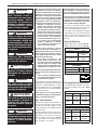 3
3
-
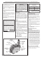 4
4
-
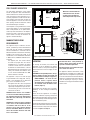 5
5
-
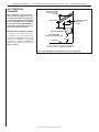 6
6
-
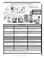 7
7
-
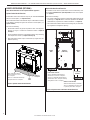 8
8
-
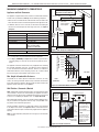 9
9
-
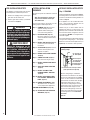 10
10
-
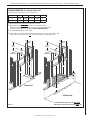 11
11
-
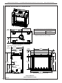 12
12
-
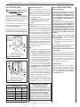 13
13
-
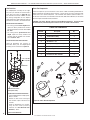 14
14
-
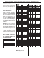 15
15
-
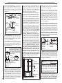 16
16
-
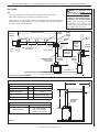 17
17
-
 18
18
-
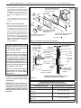 19
19
-
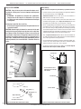 20
20
-
 21
21
-
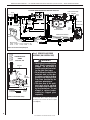 22
22
-
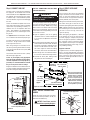 23
23
-
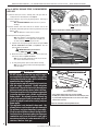 24
24
-
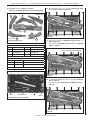 25
25
-
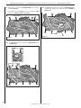 26
26
-
 27
27
-
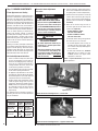 28
28
-
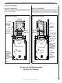 29
29
-
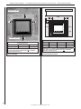 30
30
-
 31
31
-
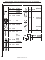 32
32
-
 33
33
-
 34
34


Astria Fireplaces MONTEBELLO ST Guide d'installation
- Catégorie
- Cheminées
- Taper
- Guide d'installation
dans d''autres langues
Documents connexes

Autres documents
-
Superior Fireplaces DRT63ST Mode d'emploi
-
-
-
-
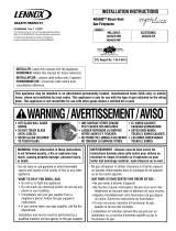 Lennox Hearth ADAGIO-EN Manuel utilisateur
-
-
-
-
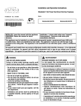 Astria Montebello DLX Mode d'emploi
-
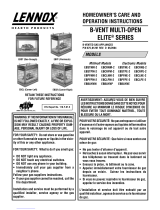 Lennox Hearth EBBAYNM Manuel utilisateur


