Jenn-Air JDB3600AWP1 Guide d'installation
- Catégorie
- Lave-vaisselle
- Taper
- Guide d'installation

]ENN-AI _®
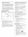
INSTALLATION INSTRUCTIONS
UNDERCOUNTER DISHWASHER
INSTRUCTIONSD'INSTALLATION
LAVE-VAISSELLESOUS PLAN DE TRAVAIL
Table of Contents ................................... 2
Table des matieres .................................. 26
W10208727A

Table of Confenfs
Dishwasher Safety ................................. 2
Installation Requirements ........................... 3
Tools and Parts ................................... 3
Location Requirements ............................ 4
Drain Requirements ............................... 6
Water Supply Requirements ........................ 6
Electrical Requirements ............................ 6
Installation Instructions ............................. 7
Prepare Cabinet Opening--Existing Utilities ........... 7
Prepare Cabinet Opening--New Utilities .............. 7
Prepare and Route Water Line ...................... 8
install Drain Hose ................................ 9
install Moisture Barrier (on some models) ........... 10
Prepare Dishwasher ............................. 11
Make Power Supply Cord Connection ............... 12
Installation instructions (cont.}
Determine Cabinet Opening ....................... 13
install the Door Handle (on some models) ........... 14
install Custom Panel ............................. 14
Choose Attachment Option ........................ 16
Move Dishwasher into Cabinet Opening ............. 17
Connect to Water Supply ......................... 19
Connect to Drain ................................ 20
Make Direct Wire Electrical Connection .............. 20
Secure Dishwasher in Cabinet Opening ............. 22
Complete Installation ............................. 23
Check Operation ................................. 24
If Dishwasher Does Not Operate ................... 24
Additional Tips .................................. 24
DISHWASHER SAFETY
Your safety and the safety of others are very important.
We have provided many important safety messages in this manual and on your appliance. Always read and obey all safety
messages.
This is the safety alert symbol.
This symbol alerts you to potential hazards that can kill or hurt you and others.
All safety messages will follow the safety alert symbol and either the word "DANGER" or "WARNING."
These words mean:
You can be killed or seriously injured if you don't immediately
follow instructions.
You can be killed or seriously injured if you don't follow
instructions.
All safety messages will tell you what the potential hazard is, tell you how to reduce the chance of injury, and tell you what can
happen if the instructions are not followed.
Tip Over Hazard
Do not use dishwasher until completely installed.
Do not push down on open door.
Doing so can result in serious injury or cuts.
You Need to:
, Slowly open dishwasher door while someone grasps the
rear of the dishwasher. Remove shipping materials, drain
hose and lower rack. Close dishwasher door until latched.
, Observe all governing codes and ordinances.
, install this dishwasher as specified in these instructions.
, installation should be performed by a qualified service
technician. The dishwasher must be installed to meet all
electrical and plumbing national and local codes and
ordinances.
2

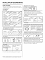
iNSTALLATiON REQUIREMENTS
Tools and Parts
Gather the recommended tools and parts before starting
installation. Read and follow the instructions provided with
any tools listed here.
All Installations
Tools needed:
_,. _ z_..._ Flat-blade
r,,ers I screwdriver
i
5/16" and 1/4" _ UL listed or CSA
nut drivers or S/ approved twist-on _
hex sockets _ wire connectors* v
10" adjustable wrench 5/8" open -end
that opens to wrench
1.18" (2.9 cm) _.
If installing custom front panels,
Torx T15 screwdr ver
-Must be the proper size to connect _'our household wiring
to 16-gauge wiring in dishwasher
Other useful items you may need:
Flashlight _ Bathtowel __
Parts supplied:
I 2- Drain hose clamps I [ 2-#10x 1/2"
(1 large and 1small)silver_ Green_ Drai_ sPch_l_iwps-head77
Make sure all these parts are included in the literature package.
Parts needed:
90° Elbow,fitting with Teflon_ tape or pipe joint
3/8 N.P.T.external threads compound
(the other end must fit your
4 #10 x 1/2" wood screws (if installing custom front panels)
® Teflon is a registered trademark of E.I. Du Pont de Nemours and Company.
t® TORX is a registered trademark of Acument Intellectual Properties, LLC.
Other parts you may also need:
1_-1/2,-2,' _ I Maskingor_
(3.8t=5,0cm) I ducttap e I
screw tYpe I
c!amps (3 max)I
NOTE: Parts available for purchase in plumbing supply stores.
Check local codes. Check existing electrical supply. See
"Electrical Requirements" section. It is recommended that
electrical connections be made by a licensed electrical installer.
In addition, for first=time installations
Tools needed:
i ii _ / ii
Cordless drill
with 1/2", 3/4'!
and 1-1/2', hole
Saw bits
tubing cutter Wire stripper
Parts needed:
Copper tubing (3/8" see'Electrical Requirements" section
O D suggested) or ....
flexible braided For Direct Wire: For Power Supply
water suoo v l n_ uSe UL Listed/ cord: use UL
..... '-'-_" - CSA certified listed power
I strain;:e!iefto supp!y cord kit
ttk& fit 7/8 (2120m)PartNUmber4317824
h01e marked for uSe
-_ '' With dishwasher
Additional parts supplied with top-venting models only:
Additional parts supplied with certain models only:
und pad docated IM0!sturebarr!ertape
ok/ ........ ! I
Make sure all these parts are included in the literature package.
If parts are not included, call 1-800-688-1100.

Location Requirements
Grounded electrical supply required.
Do not run drain lines, water lines or electrical wiring where
they can interfere with or contact dishwasher motor or legs.
The location where the dishwasher will be installed must
provide clearance between motor and flooring. Motor
should not touch the floor.
Do not install dishwasher over carpeted flooring.
Shelter dishwasher and water lines leading to dishwasher
against freezing. Damage from freezing is not covered by
the warranty.
A side panel kit is available from your dealer for installing
your dishwasher at the end of your cabinetry.
A moisture barrier accessory (Part Number 4396277) is
available from your dealer for installing underneath the
countertop. Call 1=800=688=1100 to order.
Check location where dishwasher will be installed. The
location must provide:
easy access to water, electricity and drain.
convenient access for loading and unloading dishes.
Corner locations require a 2" (5.1 cm) minimum
clearance between the side of the dishwasher door
and the wall or cabinet.
square opening for proper operation and appearance.
cabinet front perpendicular to floor.
level floor. (If floor at front of opening is not level with
floor at rear of opening, shims may be needed to level
dishwasher.)
Helpful Tip: Be sure to accurately measure dimensions
and ensure dishwasher is level if the floor in the
dishwasher opening is uneven (example: Flooring
extends only partway into opening).
NOTE: To avoid shifting during dishwasher operation,
shims must be securely attached to the floor.
If dishwasher will be left unused for a period of time or in a
location where it may be subject to freezing, have it
winterized by authorized service personnel.
Make sure pipes, wires and drain hose are within the
shaded area shown in the "Product and Cabinet
Opening Dimensions" section.
4

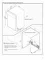
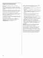
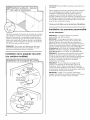
Product and Cabinet Opening Dimensions
J
*Insulation may be compressed
(not used on al models:_
NOTE: Shaded areas of cabinet walls show where
utility connections may be installed.
*Measured from the lowest pointon the
underside of countertop. May be reduced to
33 7/8" (86 cm) by removing wheels from
dishwasher.
**Minimum, measured from narrowest point of /
opening.
Check that all surfaces have no protrusions
that would prohibit dishwasher installation.
cco
_0. /

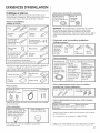
Drain Requirements
. A new drain hose is supplied with your dishwasher.
If drain hose is not long enough, use a new drain hose
with a maximum length of 12' (3.7 m) (Part Number
3385556) that meets all current AHAM/IAPMO test
standards, is resistant to heat and detergent, and fits the
1" (2.5 cm) drain connector of the dishwasher.
Make sure to connect drain hose to waste tee or disposer
inlet above drain trap in house plumbing and 20"
(50.8 cm) minimum above the floor. It is recommended
that the drain hose either be looped up and securely
fastened to the underside of the counter, or be connected
to an air gap.
Make sure to use an air gap if the drain hose is connected
to house plumbing lower than 20" (50.8 cm) above
subfloor or floor.
Use 1/2" minimum I.D. drain line fittings.
If required, the air gap should be installed in accordance
with the air gap installation instructions. When you are
connecting the air gap a rubber hose (not provided) will
be needed to connect to the waste tee or disposer inlet.
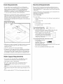
Water Supply Requiremenfs
* A hot water line with 20-120 psi (138-862 kPa) water
pressure can be verified by a licensed plumber.
* 120°F (49°C) water at dishwasher.
* 3/8" O.D. copper tubing with compression fitting or
flexible braided water supply line (Part Number
4396897RP)
NOTE: 1/2" minimum plastic tubing is not recommended.
* A 90° elbow with 3/8" N.P.T. external pipe threads on one
end.
* Do not solder within 6" (15.2 cm) from water inlet valve.
Eiecfrical Requiremenfs
Be sure that the electrical connection and wire size are
adequate and in conformance with the National Electrical
Code, ANSl/NFPA 70 - latest edition and all local codes and
ordinances.
A copy of the above code standards can be obtained from:
National Fire Protection Association
One Batterymarch Park
Quincy, MA 02269
You must have:
120-volt, 60 Hz, AC-only, 15 or 20 amp, fused electrical
supply.
copper wire only.
We recommend:
a time-delay fuse or circuit breaker.
a separate circuit.
if connecting dishwasher
with a power supply cord:
Use UL listed power supply cord kit (Part Number
4317824) marked for use with dishwasher.
Power supply cord must plug into
a grounded 3 prong outlet, located in
the cabinet next to the dishwasher
opening. Outlet must meet all local
codes and ordinances.
if connecting dishwasher with direct wiring:
* Use flexible, armored
or nonmetallic
sheathed, copper wire
with grounding wire
that meets the wiring requirements for your home and
local codes and ordinances.
* Use a UL Listed!CSA Certified strain relief.

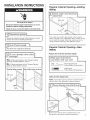
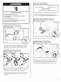
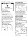
iNSTALLATiON iNSTRUCTiONS
Electrical Shock Hazard
Disconnect electrical power at the fuse box or circuit
breaker box before installing dishwasher.
Failure to do so can result in death or electrical shock.
I Dis_ebo_orci_Jt I
_al!ing dishwasher.
Yes'FollOw instructi0ns in the "PrePare cab!net
Opening_Existing Utilities!! section_
NO_FollowinstruetionS n the-prepare Cabinet
Opening_New Uti!ities sectionl
_: E :isting hookups g t ity hookups
Water line
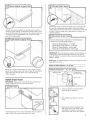
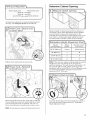
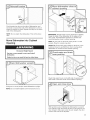
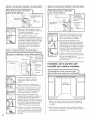
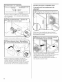
Prepare Cabinet OpeningmExisfing
Utilities
If the water line and the cable extend to the locations
shown, proceed to the "Install Drain Hose" section. If they
do not reach far enough, follow the instructions in the
"Prepare Cabinet Opening--New Utilities" section.
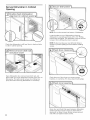
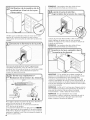
Prepare Cabinet OpeningmNew
Utilities
Prepare and route the electrical supply
i i i_i
Option A, Power Supply Cord:
NOTE: A grounded 3 prong outlet is required inside a
cabinet next to the dishwasher cabinet opening.
Drill a 1 1/2" (3.8 cm) hole in cabinet side or rear.
See product and cabinet opening dimensions.
7

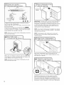
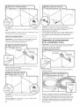
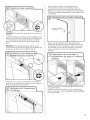
Woodcabinet:Sandtheholeuntilsmooth.
Metalcabinet:Coverholewithgrommetincludedwith
powersupplycordkit.
OptionB, Direct Wire:
Helpful Tip: Wiring the dishwasher will be easier if you
route the cable into the cabinet opening from the right-hand
side.
Drill a 3/4" (1.9 cm) hole in right-hand cabinet side or rear.
See product and cabinet opening dimensions.
Wood cabinet: Sand the hole until smooth.
Metal cabinet: Cover hole with grommet (Part Number
302797 - not provided).
8
Route cable from power supply through cabinet hole (cable
must extend to the right front side of cabinet opening).
Tape cable to the floor in area shown. This will prohibit
cable from moving when dishwasher is moved into
cabinet opening.
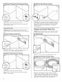
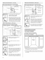
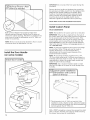
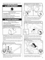
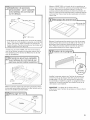
Prepare and Route Wafer Line
Helpful Tip: Routing the water line through the left side
of cabinet opening will make water connection easier.
Drill a 1/2" (1.3 cm) hole in the cabinet side or rear.
Measure overall length of copper tubing or flexible
braided water supply line. Attach to the hot water line
using a connection configuration that is in compliance
with local codes and ordinances. The water line to the
dishwasher should have a manual shutoff valve.

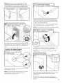
Slowlyroutewatersupplylinethroughholeincabinet.
(Ifusingcoppertubing,itwillbendandkinkeasily,sobe
gentle.)Itshouldbefarenoughintothecabinetopening
toconnectittothedishwasherinletonthefrontleft
sideofthedishwasher.
Slowlyturnwatershutoffvalveto "ON"position.Flush
waterintoashallowpanuntilcleartogetridofparticles
thatcouldclogtheinletvalve.Turnshutoffvalveto
"OFF"position.
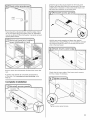
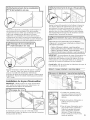
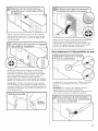
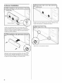
InstallDrain Hose
IMPORTANT: Always use a new drain hose. Check local
codes to determine if an air gap is required.
If needed, drill a 1 1/2" (3.8 cm) diameter hole in cabinet
wall or side of the opening closest to the sink.
Route drain hose as shown through hole in cabinet to the
front center of opening where drain connection will be
made. Tape drain hose to the floor in area shown. This will
prohibit it from moving when dishwasher is moved into
cabinet opening.
' option C, Waste dispose r _ with air gap
_Opt on D' No Waste d sposer-with a r gap
IMPORTANT: The drain hose connection of the disposer or
a waste tee must be made before the drain trap and at
least 20" (50.8 cm) above the floor where the dishwasher
will be installed.
Helpful Tip: To reduce vibration of the hose, keep the hose
away from the floor.
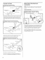
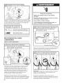
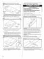
Option A, Waste disposer - no air gap
1. Using a hammer and screwdriver,
knock plug into disposer.
2. Use needle-nose pliers to remove
plug.
3. Attach drain hose to disposer inlet
with large silver drain hose clamp
(provided). Use pliers to squeeze
clamp open and move into position.

1.Connectblackendofofdrainhoseto
wasteteeandcutifneeded.
(Donotcutribbedsection.)
2.Attachblackendofdrainhosetowaste
teewithalargesilverdrainhoseclamp
(provided).Useplierstosqueezeclamp
openandmoveintoposition.Ifthedrain
hosewascut,usea11/2"to2"(3.8to
5cm)screw-typeclamp(notprovided).
OptionC,Wastedisposer- withairgap
Drain trap
1. Using a hammer and screwdriver,
knock plug into disposer.
2. Use needle-nose pliers to remove
plug.
3. Connect black end of drain hose to air
gap and cut if needed. (Do not cut
ribbed section.)
4,
5,
Attach drain hose to air gap with large
silver drain hose clamp (provided).
Use pliers to squeeze clamp open and
move into position. If the drain hose
was cut, use a 1 1/2" to 2" (3.8 to
5 cm) screw-type clamp (not
provided).
Use a rubber hose (not provided) with
screw-type clamps (not provided) to
connect from air gap to disposer inlet.
Option D, No waste disposer - with air gap
i:
hose
D r
2,
3,
Connect black end of drain hose to air
gap and cut if needed. (Do not cut
ribbed section.)
Attach drain hose to air gap with large
silver drain hose clamp (provided).
Use pliers to squeeze clamp open and
move into position. If the drain hose
was cut, use a 1 1/2" to 2"(3.8 to 5 cm)
screw-type clamp (not provided).
Use a rubber hose (not provided) with
screw-type clamps (not provided) to
connect from waste tee to air gap.
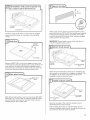
Install Moisture Barrier
(on some models)
I
Moisture
barrier
I
1. Make sure the area under the cabinet is clean and dry
for installation of the moisture barrier.
2. Remove the backing of the moisture barrier and apply
to underside of the countertop along the front edge of
the counter.
10

iiii;ii_il;ii_il;iiiiii........................................................................................................;i_iiiiii_;,,,,,,,,_,i_;ii,i_;ii,i_;ii,i_;ii,i_;ii,i_;ii,i_;i_;;ii;i_;;ii;i;i:_ii,:,i:_ii,:,i:_ii,:,i:_ii,:,i:_ii,:,i:_ii,:,i:_ii,:,i:_ii,:,i:_ii,:,i:_ii,:,:,i:_i;i_;;ii;_;i_;;ii;_;_;i_:_:_:_i;_;_;i_:_i;_;i_:ii,:,i:_i:i_;i;i:_ii,:,i:_ii,:,i:_ii,:,i:_ii,:,i:_ii,:,i:_ii,:,i:_ii,:,i:_ii,:,i:_ii,:,i:_ii,:,i:_ii,:,i:_ii,:,i:_ii,:,i:_ii,:,i:_ii,:,i:_ii,:,i:_ii,:,i:_ii,:,i:_ii,:,i:_ii,:,i:_ii,:,i:_ii,:,i:_ii,:,i:_ii,:,i:_ii,:,i:_ii,:,i:_ii,:,i:_ii,:,i:_ii,:,i:_ii,:,i:_ii,:,i:_ii,:,i:_ii,:,i:_ii,:,i:_ii,:,i:_:i,il
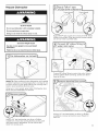
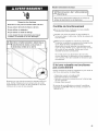
Prepare Dishwasher
Tip Over Hazard
Do not use dishwasher until completely installed.
Do not push down on open door.
Doing so can result in serious injury or cuts.
Excessive Weight Hazard
Use two or more people to move and install
dishwasher.
Failure to do so can result in back or other injury.
Helpful Tip: Place cardboard under dishwasher until installed
in cabinet opemng to avoid damaging floor covering, Do not
use door panel as a work table without first covering with a
towel to avoid scratching the door panel.
Using two or more people, grasp sides of dishwasher door
frame and place dishwasher on its back.
Using a 1/4" hex head socket, nut driver or Phillips
screwdriver, remove two screws attaching access panel
and lower panel to dishwasher. Do not remove tech
sheet from access panel.
Apply Teflon ® tape or pipe joint compound to 90 °elbow
fitting (not provided). Wrap tape around coarse threads
two to four times to prohibit leaks.
Connect 90 ° elbow fitting to water inlet valve. Using a
wrench, tighten elbow until snug, and be sure that it
faces to the rear.
Using a 1/4" hex head socket, nut driver or Phillips
screwdriver, remove terminal box cover. Retain for
later use.
11

InstallaULListed/CSACertifiedstrainrelief.Makesure
screwheadsarefacingtotheleftwhentighteningconduit
nut.Strainreliefisprovidedwiththepowersupplycordkit.
connection will you use? |
Power Supply Cord:
Follow Option A instructions
Direct Wire'
- Follow Ophon B instructions
.................................................................................
Make Power Supply Cord Connection
Option A, Power Supply Cord:
Route cord so that it does not touch dishwasher motor
to lower part of dishwasher tub. Pull cord through strain
relief in terminal bow. Take notice when installing or
removing the dishwasher in order to reduce the chance
of damaging the power supply cord.
Select UL Listed/CSA Certified twist-on wire connectors
(included with power supply cord kit) rated to connect
your household wiring to 16-gauge dishwasher wiring.
Electrical Shock Hazard
Electrically ground dishwasher.
Connect ground wire to green ground connector
in terminal box.
Do not use an extension cord.
Failure to follow these instructions can result in
death, fire, or electrical shock.
©
Remove the green grounding screw and place through
the ring terminal of the green ground wire. Reattach and
tighten the green screw.
Power Cord--Connect
remaining wires
NOTE: Twist on wire connector. Gently tug on wires to
be sure both are secured.
Connect wires black to black and white to white, using
UL Listed!CSA Certified twist-on wire connectors
(included with power supply cord kit).
12

L::::::::::::::::::::::::::::::::::::::::::::::::::::::::::::::::::::::::::::::::::::::::::::::::::::::::::::::::::::::::::::::::::::::::::::::::::::::::::LJ
Ifneeded,seewebsiteforanimatedrepresentationof
thisstep.Visitwww.jenn-air.eomunderFAQtab.
Tightenstrainreliefscrewstosecurecord.
Placewiresinsideterminalbox.Inserttabsonleftside
ofcover.Makesurewiresaretuckedinsidebox.Close
coverensuring wires are not pinched. Use 1/4" nut
driver and previously removed screw to secure cover.
NOTE: Do not plug into outlet until instructed to do so.
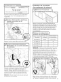
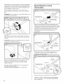
Defermine Cabinet Opening
Measure height of cabinet opening from underside of
countertop to floor where dishwasher will be installed
(you will need to measure the lowest point on the
underside of the countertop and the highest point on the
floor). Refer to "Dishwasher Height Adjustment Chart"
for wheel position and the number of turns needed.
Cabinetopeningheight positionWhee!" on front leg
33 7/8,(86:0cm)' I All the way up
34" 10
34 1i2;, (87:6 cm)
NOTE: If the minimum cabinet opening height is less than
34"(86.4 cm), the rear wheels can be removed for
additional clearance. This will allow the dishwasher to fit
into a 33 7/8" (86 cm) high cabinet opening, but the
dishwasher will be more difficult to move. (Measurements
are approximate. Wheels and legs are preset at the
factory for 34 1/2" [87.6 cm].)
..........Adjust wheels and legs
Turn both leveler legs to the same height. Put wheels in
the required position determined from "Dishwasher
Height Adjustment Chart."
13

Built-upfloors(Kitchenfloorheightishigherthan
cabinetopening.)Example:Kitchenfloortiledoesnot
extendintocabinetopening.Addshimsasneededinthe
areashowntobringthedishwasherupto34"(86.4cm)
belowthecountertop.
NOTE:Shimsmustbesecurelyattachedtofloortoavoid
movementwhenthedishwasherisinuse.
Install the Door Handle
(on some models)
Mounting
stud
, Setscrew
(in bottom
of handle)
Allen wrench
14
IMPORTANT: Do not scratch the front panel during this
procedure.
Remove the door handle and hardware bag containing
the setscrews and Allen wrench from the cardboard box.
Setscrews are already installed in the handle. Place
handle on mounting studs with the setscrews facing
down. Push the door handle tightly against the door.
Insert the short end of the Allen wrench into the
setscrews. Tighten the setscrews 1/4 turn past snug.
Retain Allen wrench with Installation Instructions.
Install Custom Panel
(Model JDB3600AWX)
NOTE: The handle for the custom panel is not included.
IMPORTANT: If the handle is attached from the back of
the custom panel, the screw holes should be countersunk
for the screws heads to be flush with the panel. If the
handle is attached to the front of the custom panel, the
screw lengths cannot exceed the panel thickness. For
more information on Jenn-Air custom handle selection,
refer to the Jenn-Air Catalog, visit www.jenn-air.com, or
call 1-800-688-1100.
NOTE: A customer-supplied full front panel must weigh
no more than 16 Ibs (7.3 kg) and must be made to
specific dimensions. It is recommended that a
cabinetmaker cut the custom panel because of the
precise dimensions needed.
NOTE: All mounting hardware supplied is for a 3/4"
(19.1 mm) thick wood panel. If a thinner wood panel, or
materials other than wood are used, it is the customer's
responsibility to obtain the proper length screws and
adjust the pilot holes accordingly.
IMPORTANT: Use a moisture-resistant sealer on both
sides and all edges of the panel to avoid damage from
humidity.
........1-1........
-:J Dishwashers with control |
panel on the top |
/
3/4" (19.1 mm)
*This dimension is for 4" (10.2 cm) toe kick. If the
installation needs a higher toe kick, adjust the height
of the wood panel accordingly. Not recommended for
toe kicks greater than 6" (15.2 cm).
With a TORX _)screwdriver, remove three screws from both
sides, as shown; hold the outer panel up while removing
the screws. Save screws for reinstallation.

Dishwashers with control panel on
P P
....j
3 screws
per side
outer [
Gently set outer panel aside. Lay the customer-supplied
custom panel face down on a covered, non-scratching
surface.
Mark line
9 29/32"
(25.2 cm)
p edge
Measure 9 29/32" (25.2 cm) from top edge and mark a line
on the back of customer-supplied custom panel. Position the
outer panel on the back of the customer-supplied custom
panel as shown, so that the top holes in the outer panel are
on the line, and both panels are centered side to side.
Mark pilot
holes
Mark all four hole locations; remove outer panel. Drill 3/32"
pilot holes 1/2" (13 mm) deep in customer-supplied custom
panel. Place the outer panel on the back of the customer-
supplied custom panel; align holes.
Attach outer panel to back of customer-supplied custom
panel with the four #10-16 x 3/8" hex head screws supplied
in the literature package. Attach the handle. The handle
should be centered on the front of the customer-supplied
custom panel in the area shown.
IMPORTANT: Screw heads must be flush with back of
customer-supplied custom panel.
R
3 screws
each side
top
edges
Customer-supplied
panel
J
Attach the panel assembly to the door by reinstalling the
three screws on each side; do not tighten completely. This
reinstallation of the three screws will hold the panel
assembly in place on the door frame,
Customer-supplied
panel
edges
i Drillthrough
these holes
Align the top edge of the customer-supplied custom
panel with the top of the console.
Drill two 3/32" pilot holes 1/2" (13 mm) deep, into the
customer-supplied custom panel, through the holes in the
top corners on the inner panel, as shown.
15

edges
:)rill through
these holes
Customer-supplied
panel
Install the two #8-18 x 1 3/8" screws from
the literature package in the top corners of the inner
panel. Tighten the six side screws reinstalled in Step 6.
Choose Affechmenf Option
Excessive Weight Hazard
Use two or more people to move and install
dishwasher.
Failure to do so can result in back or other injury.
Using two or more people, stand the dishwasher up.
Option 1, Countertop attachment:
IMPORTANT: The dishwasher must be secured to the
cabinet. There are two brackets on top of the dishwasher
that can be attached to the countertop if it is wood,
laminate or other similar surfaces. If your countertop is
marble, granite or other hard surface, the brackets may
be moved to the sides of the dishwasher.
NOTE: Do not attach the dishwasher. This will be done
later.
Option 2, Dishwasher side attachment:
tabs
To remove the brackets from the top, flatten tab at back
of brackets with pliers, and pull the brackets out of the
slots.
Break off the end of the bracket along the scored line.
With another person holding the rear of the dishwasher
to keep it from tipping, open dishwasher door and place
towel over pump assembly and spray arm of dishwasher.
This will keep screws from falling into pump area when
you are securing dishwasher to cabinet.
plastic
button
\
Push the plastic buttons out of the side of the tub.
NOTE: Save the buttons to cover the holes after
dishwasher is installed.
16

Pushbracketintoslotonthesideofdishwasher,and
bendtabintowardthesideofthedishwashersothatit
keepsthebracketinplace.Repeatthisstepfortheother
sideofthedishwasher.
NOTE:Donotattachthedishwasher.Thiswill bedone
later.
Move Dishwasher into Cabinet
Opening
Excessive Weight Hazard
Use two or more people to move and install
dishwasher.
Failure to do so can result in back or other injury.
Using two or more people, stand dishwasher upright.
NOTE: Do not install kickplate until instructed to do so.
iMPORTANT: Double-check correct placement of utilities.
Grasp the sides of the dishwasher at the edges of the
door panel. Tilt dishwasher backward on wheels and
move dishwasher close to cabinet opening.
NOTE: Do not push on the front of the panel or on the
console. Panel or console may dent.
Helpful Tip: Temporarily tape utilities to the floor in the
locations shown to prohibit them from moving when
dishwasher is moved into the cabinet opening.
Check that water line is on the left side of opemng and
drain hose is near the center of the cabinet opening.
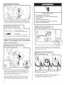
With another person holding the dishwasher to avoid it
from tipping, open and close the door a few times. If the
door closes or falls open under its own weight, the door
tension will need to be adjusted.
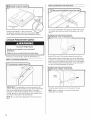
17

ssdng
.nsioner _ o
To adjust the door spring tension, unhook the spring
from the rear leg of dishwasher.
Using a 5/16" nut driver or hex socket, remove the screw
from the tensioner.
The screw can be put into one of three holes Inl,[],_31
in the front leg of dishwasher. If the door closes by itself,
move the tensioner to a higher number hole and replace
screw. Reattach door spring to rear leg.
NOTE: Tensioners on both sides of dishwasher should be
secured at same holes.
When door is unlatched, and door opens by itself, move
the tensioner to a lower numbered hole and replace the
screw. Reattach door spring to rear leg.
NOTE: Tensioners on both sides of dishwasher should
be secured at same holes.
18
Insulation
blanket
IMPORTANT: If wheels were removed, avoid damage to
the floor when moving the dishwasher. Slowly move
dishwasher completely into cabinet opening. Do not kink
or pinch water line, drain hose, power supply cord or
direct wire between dishwasher and cabinet. Remove
cardboard from under dishwasher.
NOTE: It is all right if dishwasher fits tightly into cabinet
opening. Do not remove insulation blanket-the blanket
reduces the sound level.
NOTE: If using power cord, make sure to route end
through hole in cutout before sliding dishwasher into
cabinet opening.
Align front of dishwasher door panel with front of
cabinet doors. You may need to adjust alignment to be
even with your cabinets.
Check that leveling legs are firmly against the floor.
Close and latch the door, and place level against the
front panel. Check that dishwasher is centered from front
to back in the opening. If needed, adjust leveling leg until
dishwasher is plumb. Repeat for other side of dishwasher.

Helpful Tip: Push up on front of dishwasher to raise
dishwasher offthe ground to adjust front legs. With
some installations, it may be easier to adjust the front leg
using the 3/16" hex head socket or adjustable wrench.
Place level against top front opening of tub. Check that
dishwasher is level from side to side. If dishwasher is not
level, adjust front legs up or down until dishwasher is
level.
ii iiii
Connect to Water Supply
Copper tubing only: Slide nut then ferrule onto copper
tubing about 1" (2.5 cm).
NOTE: To avoid vibration during operation, route the
water supply line so that it does not touch the
dishwasher base, frame or motor.
Copper tubing only: Put the tubing into the 90° elbow
fitting as far as it will go (the copper tubing bends and
kinks easily). Slide the nut and ferrule forward and start
the nut onto the elbow threads.
Flexible braided connection: Secure nut to elbow using
5/8" open ended wrench or adjustable wrench.
NOTE: Do not use Teflon ®tape with compression fittings.
Hold the 90° elbow fitting still with one adjustable wrench
and tighten the nut with second adjustable wrench.
Helpful Tip: For easier access, use a 5/8" open ended
wrench to tighten connection.
Place paper towel under 90° elbow fitting. Turn on water
supply and check for leaks. If leak occurs, repeat
previous step.
If needed, see website for animated representation
of this step. Visit www.jenn-air.com/watersuppl¥ under
FAQ tab.
19

_1__i_iiiiiiiiii_i_ ¸il¸ii_ii_i_iiiii_i_ii_ii'ii¸I¸ii'ii¸I¸ii'ii¸I¸ii'ii¸I¸ii'ii_iii'i'ii_i_i_ii_iiiiiiiiiiiiiii/i/iiiiiiii_ii}iiii_i_ii}iiii_i_ii}iiii_i_ii}iiii_i_ii}iiii_i_ii}iiii_i_ii}iiii_i_ii}iiii_i_ii}iiii_i_ii}iiii_i_ii}iiii_i_ii}iiii_i_ii}iiii_i_ii}iiii_i_ii}iiii_i_ii}iiii_i_ii}iiii_i_ii}iiii_i_ii}iiii_i_ii}iiiiiiiiiiiiiiii:_ii_iiiiiiiiiiiiiiiiiiiii
Connect to Drain
1_ Connect drain hose
Green clamp
Black drain hose
connector--
Place towel under drain hose to catch any water in drain
hose. Place the small green drain hose clamp onto the
small end of the drain hose. Push the new drain hose
into the black drain hose connector up to the drain hose
stop.
Using pliers, squeeze open the small green drain hose
clamp and slide onto connector between stops.
3_ Hose clamp final position
Drain hose
Black drain hose
connector --
Green clamp
hose stop
Stop
After hose is connected, remove towel.
If needed, see website for animated representation of
this step. Visit www.ienn-air.earn/drain under FAQ tab.
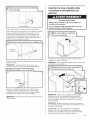
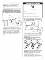
Make DirectWire Electrical
Connection
NOTE: If the power supply cord was connected earlier,
proceed to "Secure Dishwasher in Cabinet Opening"
section.
Option B, Direct Wire:
Route cable so that it does not touch dishwasher motor
or lower part of dishwasher tub. Pull cable through UL
Listed!CSA Certified strain relief in terminal box. Strain
relief is not supplied with the dishwasher. Customer
must purchase a 7/8" screw-in type strain relief.
Select UL Listed!CSA Certified twist-on wire connectors
(not included) rated to connect your household wiring to
16-gauge dishwasher wiring.
20
La page est en cours de chargement...
La page est en cours de chargement...
La page est en cours de chargement...
La page est en cours de chargement...
La page est en cours de chargement...
La page est en cours de chargement...
La page est en cours de chargement...
La page est en cours de chargement...
La page est en cours de chargement...
La page est en cours de chargement...
La page est en cours de chargement...
La page est en cours de chargement...
La page est en cours de chargement...
La page est en cours de chargement...
La page est en cours de chargement...
La page est en cours de chargement...
La page est en cours de chargement...
La page est en cours de chargement...
La page est en cours de chargement...
La page est en cours de chargement...
La page est en cours de chargement...
La page est en cours de chargement...
La page est en cours de chargement...
La page est en cours de chargement...
La page est en cours de chargement...
La page est en cours de chargement...
La page est en cours de chargement...
La page est en cours de chargement...
La page est en cours de chargement...
La page est en cours de chargement...
La page est en cours de chargement...
La page est en cours de chargement...
-
 1
1
-
 2
2
-
 3
3
-
 4
4
-
 5
5
-
 6
6
-
 7
7
-
 8
8
-
 9
9
-
 10
10
-
 11
11
-
 12
12
-
 13
13
-
 14
14
-
 15
15
-
 16
16
-
 17
17
-
 18
18
-
 19
19
-
 20
20
-
 21
21
-
 22
22
-
 23
23
-
 24
24
-
 25
25
-
 26
26
-
 27
27
-
 28
28
-
 29
29
-
 30
30
-
 31
31
-
 32
32
-
 33
33
-
 34
34
-
 35
35
-
 36
36
-
 37
37
-
 38
38
-
 39
39
-
 40
40
-
 41
41
-
 42
42
-
 43
43
-
 44
44
-
 45
45
-
 46
46
-
 47
47
-
 48
48
-
 49
49
-
 50
50
-
 51
51
-
 52
52


Jenn-Air JDB3600AWP1 Guide d'installation
- Catégorie
- Lave-vaisselle
- Taper
- Guide d'installation
dans d''autres langues
Documents connexes
Autres documents
-
KitchenAid KUDE48FXSS0 Guide d'installation
-
Maytag MDB8859AWW0 Guide d'installation
-
KitchenAid KUDE40CVBL1 Guide d'installation
-
-
KitchenAid KUDC10FXBL Guide d'installation
-
-
KitchenAid KUDS30IXBT3 Guide d'installation
-
Inglis GU2300XTVS1 Guide d'installation
-
Maytag MDBTT53AWB0 Guide d'installation
-
Amana ADB1600AWQ1 Guide d'installation