KitchenAid KMBP100EBS01 Guide d'installation
- Catégorie
- Fours
- Taper
- Guide d'installation

INSTALLATION INSTRUCTIONS
27" (68.6 CM) AND 30" (76.2 CM) ELECTRIC BUILT-IN
CONVECTION MICROWAVE OVEN
INSTRUCTIONS D’INSTALLATION
FOUR À MICRO-ONDES ENCASTRÉ ÉLECTRIQUE
À CONVECTION DE 27" (68,6 CM) ET 30" (76,2 CM)
W11091153A
Table of Contents/Table des matières
BUILT-IN MICROWAVE OVEN SAFETY .................................. 1
INSTALLATION REQUIREMENTS .......................................... 2
Tools and Parts .................................................................... 2
Location Requirements ....................................................... 2
Electrical Requirements ........................................................ 3
INSTALLATION INSTRUCTIONS ........................................... 4
Spacer Kit Installation .......................................................... 4
Prepare Built-In Microwave Oven ......................................... 4
Make Electrical Connection.................................................. 5
Install Microwave Oven ........................................................ 5
Complete Installation ........................................................... 6
SÉCURITÉ DU FOUR À MICRO-ONDES ENCASTRÉ ........... 7
EXIGENCES D’INSTALLATION .............................................. 7
Outils et pièces .................................................................... 7
Exigences d’emplacement .................................................. 7
Spéccations électriques ..................................................... 9
INSTRUCTIONS D’INSTALLATION ..................................... 10
Installation de la trousse d’entretoise ................................. 10
Préparation du four à micro-ondes encastré ..................... 10
Raccordement électrique ................................................... 10
Installation du four à micro-ondes...................................... 11
Achever l’installation ......................................................... 12
BUILT-IN MICROWAVE OVEN SAFETY
You can be killed or seriously injured if you don't immediately
You
can be killed or seriously injured if you don't
follow
All safety messages will tell you what the potential hazard is, tell you how to reduce the chance of injury, and tell you what can
happen if the instructions are not followed.
Your safety and the safety of others are very important.
We have provided many important safety messages in this manual and on your appliance. Always read and obey all safety
messages.
This is the safety alert symbol.
This symbol alerts you to potential hazards that can kill or hurt you and others.
All safety messages will follow the safety alert symbol and either the word “DANGER” or “WARNING.”
These words mean:
follow instructions.
instructions.
DANGER
WARNING

2
INSTALLATION REQUIREMENTS
Tools and Parts
Gather the required tools and parts before starting installation.
Read and follow the instructions provided with any tools
listed here.
Tools Needed
■ Phillips screwdriver
■ Flat-blade screwdriver
■ Measuring tape
■ Level
Parts Needed
■ A UL listed or CSA approved conduit connector
■ UL listed wire connectors
Parts Needed - Flush Installation
■ W10752697 Stainless steel flush installation kit for 30"
(76.2 cm) models
■ W10752698 Stainless steel flush installation kit for 27"
(68.6 cm) models
■ W10839402 Limited edition black flush installation kit
for 30" (76.2 cm) models
To order, see the “Assistance or Service” section of the Use
and Care Guide.
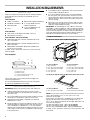
Parts Supplied
A. Spacer bars (2)
B. Bottom vent (1)
C. ³⁄
8
" hex-head washer screws (4)
D. ¾" pan-head screws (4)
Check local codes. Check existing electrical supply. See
“Electrical Requirements.”
It is recommended that all electrical connections be made
by a licensed, qualified electrical installer.
Location Requirements
IMPORTANT: Observe all governing codes and ordinances.
■ Cabinet opening dimensions that are shown must be
used. Given dimensions provide minimum clearance with
microwave oven.
■ Recessed installation area must provide complete enclosure
around the recessed portion of the microwave oven.
■ Grounded electrical supply is required. See “Electrical
Requirements” section.
■ Electrical supply junction box should be located 3" (7.6 cm)
maximum below the support surface when the microwave
oven is installed in a wall cabinet. A 1" (2.5 cm) minimum
diameter hole should have been drilled in the left rear corner
of the support surface to pass the appliance cable through
to the junction box.
■ For installation above single built-in oven, the junction box
must located inside upper cabinet.
■ If you are installing the junction box on rear wall behind
the microwave oven, the junction box must be recessed
and located in the upper or lower right or left corner of the
cabinet; otherwise, the microwave oven will not fit into the
cabinet opening.
■ Microwave oven support surface must be solid, level and
flush with bottom of cabinet cutout. Floor must be able to
support a weight of 90 lbs (41.0 kg).
IMPORTANT: To avoid damage to your cabinets, check with
your builder or cabinet supplier to make sure that the materials
used will not discolor, delaminate or sustain other damage. This
oven has been designed in accordance with the requirements
of UL and CSA International and complies with the maximum
allowable wood cabinet temperatures of 194°F (90°C).
Product Dimensions
27" (68.6 cm) and 30" (76.2 cm) Microwave Ovens
27" (68.6 cm) Models
A. 25³⁄
8
" (64.5 cm)
B. 18
5
⁄
8
" (47.3 cm) overall height
C. 26³⁄
4
" (68.0 cm) overall width
D. 21¹⁄
2
" (54.6 cm)
E. 17³⁄
8
" (44.1 cm)
30" (76.2 cm) Models
A. 28³⁄
8
" (72.1 cm)
B. 18
5
⁄
8
" (47.3 cm) overall height
C. 29³⁄
4
" (75.6 cm) overall width
D. 21¹⁄
2
" (54.6 cm)
E. 17³⁄
8
" (44.1 cm)
27" (68.6 cm) and 30" (76.2 cm) Microwave Oven Spacer Kit
27" (68.6 cm) Models
A. 26³⁄
4
" (67.9 cm) overall width
30" (76.2 cm) Models
A. 29³⁄
4
" (75.6 cm) overall width
NOTE: The microwave oven spacer kit will allow the microwave
oven to be installed in a 17³⁄
8
" to 17³⁄
4
" (44.1 to 45.1 cm)
maximum cutout height.
A microwave oven spacer kit is available from your dealer that
will allow the microwave oven to be installed in a 19
1
/
4
" to
19
11
⁄
16
" (48.9 - 50.0 cm) maximum cutout height. Match the oven
size to the following kits:
27" (68.6 cm) Stainless Steel - Spacer Kit W10469901
30" (76.2 cm) Stainless Steel - Spacer Kit W10469903
30" (76.2 cm) Limited Edition Black - Spacer Kit W10842584
To order, see the “Assistance or Service” section of the Use and
Care Guide.
■ Drill (for wall cabinet installations)
■ ¹⁄
8
" (3 mm) drill bit (for wall
cabinet installations)
■ 1" (2.5 cm) drill bit (for wall
cabinet installations)
A
B
C
D
B
E
C
D
A
A

3
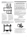
Cabinet Dimensions
27" (68.6 cm) and 30" (76.2 cm) Microwave Ovens
27" (68.6 cm) Models
A. 27" (68.6 cm) min. cabinet
width
B. 18
5
⁄
8
" (47.3 cm) from bottom of
cutout to bottom of upper
cabinet door
C. 40" (101.6 cm) bottom of
cutout to floor (recommended)
D. 25¹
⁄2
" (64.8 cm) cutout width
E. 1¹⁄
2
" (3.8 cm) min. bottom of
cutout to top of cabinet door
F. 17
5
⁄
8
" (44.7 cm) recommended
cutout height (will fit cutout
height from 17³⁄
8
" [44.1 cm] to
17³⁄
4
" [45.1 cm])
G. 21
7
⁄
8
" (55.5 cm) min. cutout
depth
30" (76.2 cm) Models
A. 30" (76.2 cm) min. cabinet
width
B. 18
5
⁄
8
" (47.3 cm) from bottom of
cutout to bottom of upper
cabinet door
C. 40" (101.6 cm) bottom of
cutout to floor (recommended)
D. 28¹⁄
2
" (72.4 cm) cutout width
E. 1¹⁄
2
" (3.8 cm) min. bottom of
cutout to top of cabinet door
F. 17
5
⁄
8
" (44.7 cm) recommended
cutout height (will fit cutout
height from 17³⁄
8
" [44.1 cm] to
17³⁄
4
" [45.1 cm])
G. 21
7
⁄
8
" (55.5 cm) min. cutout
depth
Minimum Installation Clearances
For proper installation, the following minimum clearances must
exist above and below the cabinet opening.
Installation Above Single Built-In Oven
A. Upper cabinet
B. Lower single oven
Approved models: KMBP100E and KMBP107E
Electrical Requirements
If codes permit and a separate ground wire is used, it is
recommended that a qualified electrical installer determine that
the ground path and wire gauge are in accordance with local
codes.
Check with a qualified electrical installer if you are not sure the
microwave oven is properly grounded.
This microwave oven must be connected to a grounded metal,
permanent wiring system.
Be sure that the electrical connection and wire size are adequate
and in conformance with the National Electrical Code, ANSI/
NFPA 70-latest edition or CSA Standards C22.1-94, Canadian
Electrical Code, Part 1 and C22.2 No. O-M91-latest edition, and
all local codes and ordinances.
A copy of the above code standards can be obtained from:
National Fire Protection Association
1 Batterymarch Park
Quincy, MA 02169-7471
CSA International
8501 East Pleasant Valley Road
Cleveland, OH 44131-5575
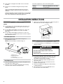
Electrical Connection
To properly install your microwave oven, you must determine
the type of electrical connection you will be using and follow
the instructions provided for it here.
■ Microwave oven must be connected to the proper
electrical voltage and frequency as specified on the
model/serial/rating plate. The model/serial/rating plate
is located underneath the control panel, along the
oven vent.
A. Model/serial/rating plate
■ The microwave oven rated 240 volt, 20-amp, has 4 wires
(L1, L2, N and G) in the flex conduit and should be
connected to a 20-amp maximum rated circuit, overcurrent
protected on both the L1 and L2 circuits.
■ A time-delay fuse or circuit breaker is recommended.
■ Flexible cable from the microwave oven should be
connected directly to the junction box.
■ Do not cut the conduit. The length of conduit provided is
for serviceability of the microwave oven.
A
B
C
D
E
F
G
1"
(2.5 cm)
1"
(2.5 cm)
fr
om top
of oven
A
B
For a permanently connected microwave oven:
The microwave oven must be connected to a grounded,
metallic, permanent wiring system, or an equipment
grounding conductor should be run with the circuit
conductors and connected to the equipment grounding
terminal or lead on the microwave oven.
GROUNDING INSTRUCTIONS
SAVE THESE INSTRUCTIONS
A

4
■ A UL listed or CSA approved conduit connector must be
provided.
■ If the house has aluminum wiring follow the procedure
below:
Connect the aluminum wiring using special connectors
and/or tools designed and UL listed for joining copper to
aluminum.
Follow the electrical connector manufacturer’s recommended
procedure. Aluminum/copper connection must conform with
local codes and industry accepted wiring practices.
For power requirements, refer to the following table:
Voltage Microwave With Convection Oven
240 VAC
19.9 A/3250 W
208 VAC
19.9 A/3250 W
INSTALLATION INSTRUCTIONS
Spacer Kit Installation
NOTES:
■ The microwave oven spacer kit allows the microwave oven
to be installed in an 17
7
⁄
16
" to 17
7
⁄
8
" (44.1 cm to 45.3 cm)
maximum cutout height.
■ If your cabinet cutout height is more than 17
7
⁄
16
" (44.1 cm),
you must install the spacer kit. Proceed to “Assemble
Spacer Kit.”
■ If your cabinet cutout height is less than 17
7
⁄
16
" (44.1 cm),
you do not have to install the spacer kit. Proceed to “Prepare
Built-In Microwave Oven.”
Assemble Spacer Kit
1. Attach the bottom vent to spacer bars using four ³⁄
8
"
hex-head washer screws.
NOTE: Spacer bar flanges should be facing out.
A. Bottom vent
B. Spacer bar flange
C. Spacer bars
D. ³⁄
8
" hex-head washer screws
Install Spacer Kit
1. Center assembled microwave oven spacer kit against lower
front edge of the cabinet cutout.
2. Using an ¹⁄
8
" (0.32 cm) drill bit, drill through the mounting
holes in the spacer bars to create pilot holes.
3. Attach the assembled spacer kit to the cabinet using four ¾"
flat-head screws. Do not overtighten screws.
A. ¾" pan-head screws
B. Spacer kit assembly
Prepare Built-In Microwave Oven
1. Locate existing wiring to avoid drilling into or severing wiring
during installation.
2. To avoid floor damage, set the microwave oven onto
cardboard prior to installation. Do not use handle or
any portion of the front frame for lifting.
3. Remove the shipping materials and tape from the
microwave oven.
4. Remove and set aside racks and other items from
inside the microwave oven.
5. Remove the hardware package from inside the bag
containing literature.
6. Move the microwave oven and cardboard close to
the microwave oven’s final location.
A
B
C
D
D
A
B
WARNING
Excessive Weight Hazard
Use two or more people to move and install
microwave oven.
Failure to do so can result in back or other injury.

5
Make Electrical Connection
This microwave oven is manufactured with a neutral (white)
power supply wire and a cabinet-connected green (or bare)
ground wire.
1. Disconnect power.
2. Feed the flexible cable conduit from the microwave oven
through the opening in the cabinet.
3. Remove junction box cover if it is present.
4. Install a UL listed or CSA approved conduit connector to
the junction box.
A. UL listed or CSA approved conduit connector
5. Route the flexible cable conduit from the microwave oven
to the junction box through a UL listed or CSA approved
conduit connector.
6. Tighten screws on conduit connector.
7. Complete electrical connection.
3-Wire Cable with Ground from Home Power Supply
to Microwave Oven Cable with 4-Wires
A. Cable from home power supply
B. Green (or bare) wires
C. White wires
D. 4-wire cable from microwave oven
E. UL listed or CSA approved conduit
connector
F. Red wires
G. Black wires
H. UL listed wire connector
I. Junction box
1. Connect the 2 black wires (G) together using a UL listed wire
connector.
2. Connect the 2 white wires (C) using a UL listed wire
connector.
3. Connect the 2 red wires (F) together using a UL listed wire
connector.
4. Connect the 2 green (or bare) wires (B) together using a UL
listed wire connector.
5. Install junction box cover.
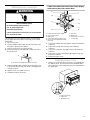
Install Microwave Oven
1. Using 2 or more people, lift the microwave oven partially into
the cabinet cutout. If a spacer kit has been installed, lift the
microwave oven over it and position the microwave between
the guide strips.
A. Spacer bar flange
B. Spacer bar
C. Microwave oven
WARNING
Electrical Shock Hazard
Disconnect power before servicing.
Use 12 gauge copper wire.
Electrically ground oven.
Failure to follow these instructions can result in death,
fire, or electrical shock.
A
B
C
D
H
F
A
G
E
I
A
B
C
C

6
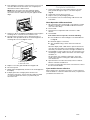
2. Push against the front frame of the microwave oven to insert
oven into cabinet. Push microwave oven completely into
cabinet and center in cabinet cutout.
NOTE: Open microwave oven door and push against
seal area of microwave oven front frame when pushing
microwave oven into cabinet. Do not push against outside
edges.
3. Using an ¹⁄
8
" (0.32 cm) drill bit, predrill pilot holes through the
mounting rails on each side of the microwave oven.
4. Securely fasten microwave oven to cabinet using two ³⁄
4
"
flathead screws provided. Insert the screws through holes in
mounting rails. Do not overtighten screws.
A. Mounting rail
B. Flat-head screws
5. Replace convection grid, turntable and support hub.
6. Reconnect power.
7. Display panel will light briefly, and the clock should appear in
the display.
8. If display panel does not light, please reference the
“Assistance or Service” section of the Use and Care Guide
or contact the dealer from whom you purchased your
microwave oven.
Complete Installation
1. Check that all parts are now installed. If there is an extra
part, go back through the steps to see which step was
skipped.
2. Check that you have all of your tools.
3. Dispose of/recycle all packaging materials.
4. For microwave oven use and cleaning, read the Use and
Care Guide.
Check Operation of Microwave Oven
1. Fill a microwave-safe container with 1 cup (250 mL) of water
and place container on the turntable inside the microwave
oven. Close door firmly.
2. Touch COOK.
3. Set power level, temperature and cook time to “2:00”
minutes.
4. Touch START.
If microwave does not operate, check the following:
■ Household fuse is intact and tight; or circuit breaker has
not tripped.
■ Electrical supply is connected;
■ See “Troubleshooting” section in the Use and Care
Guide.
When the display reads “1:00” minute, open the microwave
oven door. The microwave oven should stop cooking. Close
door firmly. The interior microwave oven light should turn off.
5. Touch START to resume a preset cycle. The microwave oven
should begin cooking, and the microwave oven interior light
should be on.
Let microwave oven complete cooking time. Tones will
sound at the end of the cooking time, and the microwave
oven will shut off.
6. Open microwave oven door and slowly remove container.
Water in container should be hot.
7. To set the clock and other microwave oven functions, refer to
the Use and Care Guide.
If you need Assistance or Service:
Please reference the “Assistance or Service” section of the Use
and Care Guide or contact the dealer from whom you purchased
your built-in microwave oven.
A
B
B
8/17
-
 1
1
-
 2
2
-
 3
3
-
 4
4
-
 5
5
-
 6
6


KitchenAid KMBP100EBS01 Guide d'installation
- Catégorie
- Fours
- Taper
- Guide d'installation