
Safety Precautions
Precautions in Use
Parts Description and Function
Preparation for Use
Items to be Sterilized
Operating Instructions
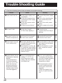
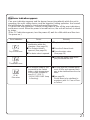
Trouble Shooting Guide
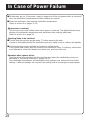
Incase of Power Failure
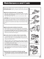
Maintenance and Care
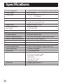
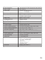
Specifications
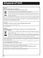
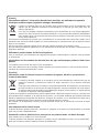
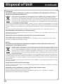
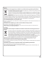
Disposal of Unit
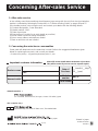
Concerning After-sales Service
・・・・・・・・ 2~8
・・・・・・・・・・ 9
・・ 10~15
・・・・・・・・・ 16
・・・・・・ 17~18
・・・・・・ 19~25
・・・・・ 26~27
・・・・・・・・ 28
・・・・・・・・ 29
・・・・・・・・・・ 30~31
・・・・・・・・・ 32~35
・・・・ 36
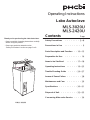
Operating Instructions
Labo Autoclave
MLS-3020U
MLS-2420U
Contents Page
Thank you for purchasing the Labo Autoclave.
・Please read this Operating Instructions carefully
before using the product.
・Please pay particular attention to the
“Safety Precautions” section on page 2 to 8.
*

2
:
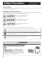
Safety Precautions These precautions must be
observed without fail.
For Your Safety
Explanation of symbol word panels
To reduce the risk of injury, loss of life, electric shock, fire, malfunction, and damage to equipment or property, always
observe the following safety precautions.
The following symbol word panels are used to classify and describe the level of hazard, injury, and property damage
caused when the denotation is disregarded and improper use is performed.
Denotes a potential hazard that could
result in serious injury or death.
Denotes a potential hazard that will
result in serious injury or death.
Denotes a hazard that could result in
minor injury.
The following symbols are used to classify and describe the type of instructions to be observed.
This symbol is used to alert users to a specific operating procedure that must not be performed.
This symbol is used to alert users to a specific operating procedure that must be followed in order
to operate the unit safely.
This symbol is contents which you take care with operation.
DANGER
CAUTION
WARNING
DANGER
Never put inflammables in the unit.
Do not put the above substances near or in the unit.
●
Explosive substances
● Ignitable substances
● Oxidizing substances
● Combustible substances● Flammable substances
Inobservance of this warning may result in injury, fire by
possible explosion or trouble with the unit.
Alcohol
Gas
Gasoline
A
Gas
line
e
e
G

3
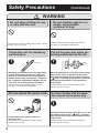
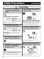
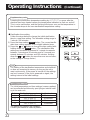
WARNING
Connect the power cord to
the outlet equipped with
a ground-fault
circuit interrupter (GFCI).
Ground the unit without fail.
Keep the power cord always
clean.
Do not open the cover when
the unit is internally
pressurized.
Otherwise, the cord may catch fire or the unit
may operate abnormally whereby causing
injury.If the unit is use in combination with other
equipment, a branched outlet may heat
abnormally and catch fire.
Connect the power cord to a plug-in receptacle
equipped with a GFCI of more than 15A. Avoid
multiple loads on a single electrical outlet.
Inobservance of this warning may result in
electric shock.
Make sure that the unit has been properly
grounded. Be sure to connect one end of
grounding wire to ground and the other end
to the grounding terminal. Inobservance of this warning may result in burns
or injury.
Do not open the cover when the pointer of the
pressure gauge indicates high pressure. Open
the cover after confirming that the pressure in
the chamber is 0 MPa (0kgf/cm2) and the
completion lamp lights up.
Dusty or wet blades may cause fire.
Wipe off dust or moisture from the power plug
blades and the base of the blades.
Check the cover packing.
Do not put anything that
corrodes stainless steel.
Inobservance of this warning
may result in injury, fire by possible explosion or
trouble with the unit.
Sterilization of animal oil and fat (e.g.,wastes
generated after BSE inspection, etc.)causes
premature wear, cracking or breakage of the
cover packing. If the unit is used with
defective packing,steam may escape and cause
burns or accidents.
Do not put anything like culture medium that
corrodes stainless steel in the unit.

4
(Continued)
Safety Precautions
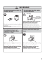
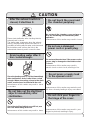
WARNING
Check the unit for sterilizing
performance.
Inobservance of this warning may result in
accident or incomplete sterilization.
Sterilizing performance will vary depending
on such factors as the type and volume of
objects to be sterilized, the arrangement of
objects and the type of container. Therefore,
use a chemical sterilization indicator like an
“OK card” for checking the performance.
Do not extend the power cord.
Inobservance of this warning may result in
electric shock or fire.
Do not connect the power cord to an
extension cord.
Pull out the power plug before per-
forming maintenance on the unit.
Inobservance of this warning may result in
electric shock or burns.
In case of trouble, stop the opera-
tion and pull out the power plug.
Inobservance of this warning may result in
electric shock or burns.
When maintaining the unit, pull out the power
plug. At this time, do not pull of the power
plug with wet hands. Set the power switch to
“ ○
○
(OFF)” and wait for the unit to cool before
performing maintenance. Pay attention to
projections.
Should trouble (burning smell, etc.) occur, set
the power switch to the “
○
(OFF)” position,
pull out the power plug and contact the place
of purchase.
Indicator
Do not allow children to use
or play with the unit.
Do not sterilize objects in a
steam- impermeable
container or bag.
Inobservance of this caution may result in burns,
electric shock or injury. Inobservance of this warning may result in
accident or incomplete sterilization.

5
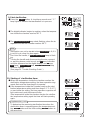
WARNING
An exhaust valve is not
opened in the state where
pressure is high.
It becomes a cause of a burn or an accident. It becomes a cause of a burn or an accident.
High temperature and high-pressure steam
and hot water blow off from an exhaust port,
and are dangerous.
Moreover, since the sterile water is high
temperature, please drain after fully cooling
down immediately after operation.
It drains, after sterile water gets
cold.
Please do the water pulling out after cooling
the sterile water because the sterile water is a
high temperature immediately after
sterilization.
Please use a heatproof hose when you
connect the hose with the outlet.
Do not disassemble, repair or
modify the unit.
Inobservance of this warning may result in fire,
malfunction or injury.
The unit is non-technical services should not
be repaired.
Do not open the drain valve
during operation.
Hot water gushes out and can cause burns or
accident. Heating water means the water that is
poured into the chamber in order to generate steam
for sterilization using the heater in the chamber.
Drain the heating water with the cover open.
Wait at least 2 hours from the end of
operation to drain the heating water.
Do not open.
Drain valve

6
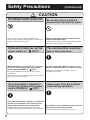
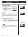
CAUTION
(Continued)
Safety Precautions
Alcohol
Well
water
Saline
water
Connect the unit’s power
cord to its own dedicated
outlet.
Inobservance of this caution may result in fire or
malfunction and eventually injury.
Connect the power cord to the dedicated
plug-in receptacle as shown below.
Single-phase,
230 V AC, 10 A or higher
Single-phase,
230 V AC, 7 A or higher
<MLS-3020U>:
<MLS-2420U>:
Do not use the unit with
other than the rated voltage.
Do not plug or unplug the
power cord with wet hand.
Inobservance of this caution may result in trouble,
fire or electric shock.
May cause electric shock.
Make sure that the unit is connected at the
rated voltage.
Nothing should be placed on
the power plug or power cord.
Inobservance of this caution may overheat the
power cord, resulting in fire.
Hold the power plug when
plugging or unplugging
the power cord.
Inobservance of this caution may result in
electric shock or short-circuit, resulting in fire.
Be sure to hold the power plug but not the
power cord when unplugging the power cord.
Use purified or tap water as
heating water.
Heating water means the water that is poured
into the chamber in order to generate steam for
sterilization using the heater in the chamber.
Do not use staples or nails
to secure the power cord.
Inobservance of this caution may overheat the
power cord, resulting in fire.
Never use alcohol and other chemicals, well
water, saline water, etc. Inobservance of this
caution may result in explosion or corrosion.
oh
er
line
Single-phase,
230 V AC, 10 A or higher
Single-phase,
230 V AC, 7 A or higher
<MLS-3020U>:
<MLS-2420U>:

7
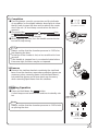
CAUTION
Do not take out the sterilized
objects immediately after
sterilization.
Inobservance of this caution may result in burns.
Since the sterilized objects are still hot, use
due care when taking them out.
Do not stick your fingers in
the hinge of the cover.
Do not touch the cover and
the chamber periphery.
Inobservance of this caution may result in your
fingers be pinched, resulting in injury.
Inobservance of this caution may result in burns.
Do not touch the chamber, cover and arm as
they are hot during and immediately after
operation.
Drain heating water after it
has cooled enough.
Inobservance of this caution may result in burns
or accident.
Do not press or apply load
to the opened cover.
Inobservance of this caution may make the unit
fall down. whereby leading to injury or accident.
Since the heating water is still hot immediately
after sterilization, drain it after it has cooled
enough. When connecting a hose to the drain
outlet, use the hose included with the unit.
After the exhaust switch is
closed, it sterilizes it.
Please start sterilization after checking that the
exhaust knob is closed.
The sterile water evaporates when the exhaust
switch is sterilized while opened and there is a
possibility of boiling without water, and steam and
the hot water come out from the hole in the
exhaust tank intensely, and it causes the burn.
Do not use a damaged
power cord or power plug.
Inobservance of this caution may result in
electric shock or short-circuit, resulting in fire.
Do not use the autoclave if the power cord or
power plug is damaged or the outlet socket
is loose.

8
CAUTION
Do not move the unit with the
exhaust tank filled with the water.
Inobservance of this caution may spill the water
whereby causing burns or accident.
When moving the unit, drain water from the
exhaust tank without fail.
The unit should be moved by
two or more persons.
Keep away from the exhaust
tank during operation.
If the unit is dropped by mistake, injury or
accident may result.
The unit weighs 64 kg. Move it in twos or more
persons, and pay attention not to pinch your feet.
Continued use of the unit when not in proper
working order may result in electric shock and fire.
If the same abnormality remains even when the
operation is reattempted, turn OFF the power
supply and contact the place of purchase.
Inobservance of this caution may burns.
Pay attention to the steam that comes out from
the exhaust tank during operation.
If any abnormality is indicated in
the process display, set the power
switch (POWER) to “
○
(OFF)”.
Pull out the power plug from the power plug
receptacle.
Inobservance of this caution may result in electric
shock, short-circuit and fire.
At the end of daily use, set the
power switch to “
○
(OFF)”.
When leaving the unit unused for a long time,
be sure to pull out the power plug, set the
power switch (POWER) to “
○
(OFF)”.
Inobservance of this caution may result in
short-circuit in current-carrying parts, resulting in
trouble, electric shock or fire.
Do not pour water on the unit.
(Continued)
Safety Precautions

9
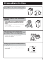
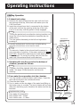
Precautions In Use
Before leaving the product unused for a long time, be sure
to set the power switch in the OFF position and shut down
the main power.
Set the power switch in the OFF position
everyday after use.
Corrosion of the chamber may cause premature
malfunction of the product.
After sterilizing culture mediums that
generated sulfide gas or chlorine gas, clean
the chamber on the inside without fail.
Do not use the product for anything other than the
intended purposes of sterilization, keep warm and
melting.
Failure to observe this caution may corrode the chamber
or clog the piping.
(Do not use the product as a cooking heater.)
Prohibition of Use for Other than Intended
Purposes
Use of well water, saline water, etc. may cause trouble.
Use purified or city water as heating water.
Purified
water City water

10
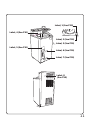
Label, 1 :
This caution label explains burning hazard with touching the chamber, door or arm,
if the unit is in operation or immediately afterward.
Label, 2 :
To avoid the malfunction of the unit in accordance with chamber corrosion, this label
explains the ban of contents use which is able to corrode stainless steel, and explains
maintenance after use.
Label, 3 :
This label explains a maintenance and cautions of lid packing.
Label, 4 :
This label explains caution for installation of the unit and maintenance.
Label, 5 :
This label explains usage of exhaust tank and its caution.
Label, 6 :
This label explains cautions of an exhaust tank.
Label, 7 :
This label explains cautions of water out letting from the drain valve.
Label, 8 :
This label explains burning hazard in accordance with issuing high temperature boiling
water from safety valve.
Explanation of Action Label
Parts Description and Function

11
Label, 5 (See P10)
Label, 4 (See P10)
Label, 8
(See P10)
Label, 2 (See P10)
Label, 3 (See P10)
Label, 6 (See P10)
Label, 7 (See P10)
Label, 1 (See P10)

12
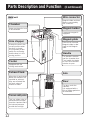
Main unit
(Continued)
Parts Description and Function
Chamber
Items are placed in here
to be sterilized.
Caster
Equipped with the
locking mechanism.
Arm stopper
It keeps the arm in the
correct position when
the door is closed.
It incorporates a door
switch for confirming
that the door is in the
closing position.
Wire-connector
Magnet-holder and han-
dle are connected by
this connector.
Magnet-holder
Permanent magnet is
equipped.
Magnet-plate
If the unit is not used,
Magnet-holder is atta-
ched to this Magnet-
plate.
Handle
The handle is used to
seal the chamber door.
Turn handle clockwise
to close and countercl-
ockwise to open.
Arm
Door
The door seals the
chamber.
It is equipped with a
silicon rubber gasket on
its underside.
Exhaust tank.
When the air and steam
within the chamber are
expelled as exhaust,
they are collected into
this tank, where it
reverts to water.
Pressure safety valve
This is a safety valve to
allow steam to escape
from the chamber that if
the internal pressure
should rise too high.

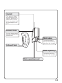
13
Drain opening cover
Gasket
This gasket is fitted to
the exhaust tank inlet
opening, where the ex-
haust hose is connec-
ted to the exhaust tank
to keep airtight conne-
ction.
Drain valve
This manual valve is
used to drain sterilizing
water from the chamber.
Exhaust hose
Conveys steam and air
from the chamber to the
exhaust tank.
Drain opening
For draining sterilizing
water from the chamber.
Exhaust tank

14
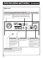
Control panel
(Continued)
Parts Description and Function
Stop button
Cancels the operation.
Pressing this button for
about one second in the
during operation causes
a beep to sound and
switches the unit to
standby status.
Start button
Starts sterilization.
Exhaust knob
This knob is used to re-
lease the air within the
chamber.
Turn clockwise this knob
to close and counterclo-
ckwise to open.Close
the knob before starting
sterilization.
Setting button
(TEMP.TIM. . )
Used for setting and displaying the steriliza-
tion temperature and sterilization time, and
for displaying the remaining sterilization time.
(Refer to pages 21-22 for detailed instructions.)
Power switch
Pressure gauge
Indicates the pressure
within the chamber.
Switch button
When pressing the switch button with magnet-
holder, Handle switch will start.

15
Digital indicator lamp
Displays the sterilization
temperature and sterili-
zation time settings alt-
ernately when the unit
is in standby status.
Displays the internal
chamber temperature
during the sterilizing op-
eration and during the
cooling operation after
finishing of this steriliz-
ation.
Indicator lights a finish-
ing mark to indicate the
completion of sterilizat-
ion.
Pressing the TEMP bu-
tton makes the indicator
to display the temperat-
ure setting, and pressi-
ng the TIMER button
makes it to display the
setting time.
These operations may
be performed on any
of the unit’s operating
modes.
Time indicator lamp
This lamp lights when
the digital indicator lamp
is displaying time infor-
mation.
Heating process indicator lamp
This lamp lights to display temperature
information and heating process of the
chamber.
When processing cooling the chamber,
this lamp flushes.
Timer operation segments
Flashes when the sterili-
zation timer is operating.
High pressure lamp
When the pressure inside the chamber is high
and the temperature inside the chamber is ov-
er 98 °
C
, this lamp will be flashing.
Door
Light when the door is
in the properly closed
position.

16
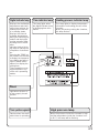
Statement of the range of environmental conditions
・indoor use
・altitude up to 2000 m
・temperature 5 °
C
to 40 °
C
・maximum relative humidity 85 %
・mains supply voltage fluctuations not to exceed ±10 %
of the nominal voltage
・transient over voltages : installation categories Ⅱ
・pollution degree 2
・do not exert vibration to the product.
That the display indications will be difficult to read, if the
unit is located under direct sunlight.
Note
●Make sure to install the unit on a flat, sturdy surface floor.
Lock all four casters.
●Avoid locations where the unit is exposed to air containing
large amounts of moisture, salt or sulfur, as these could
adversely affect the unit.
●The door opens out in a counterclockwise direction. Make
sure to allow sufficient clearance from impediments (walls,
posts, etc.) when positioning the unit.
●Allow at least 5 cm of free space between the back and left
sides of the unit and the nearest wall. Placing the unit too
close to the wall will cause heat to build up inside the unit
and that could cause the unit to malfunction.
Installation
Preparation for Use
At least 5 cm
●Allow at least 5 cm of free space between the back and left
Set the switch inside the main unit to match the elevation
of the installation location. (When the unit shipped from the
factory, it is set for an elevation of between 0 and less than
500 m.)
●If the switch setting needs to be changed, ask your dealer
to do it for you.
Settings to match elevation of installation location
Elevation
(m)
500-less than 1,000
(factory setting)
0-less than 500
1,000-less than 2,000
walls

17
●If large quantities of culture or other liquids are sterilized,
the delay of reaching time could be occurred between the
chamber reaching time to setting temperature and the liquid
in containers reaching time to setting temperature.
Set the sterilization time a little longer than usual time when
sterilizing such items.
Precautions for sterilizing of liquids such as cultures and chemicals
●Never use the unit to sterilize cultures or chemical solutions
containing elements (salt water, strong acids, strong alkalis)
that could cause the inside of the chamber (made of stain-
less steel) to corrode.
Corrosion could cause the unit to malfunction prematurely.
Timer setting = sterilization time + delay time
●Sterilization performance can vary depending on the type
of items being sterilized, their quantity, how they are loaded
into the autoclave and the containers used to hold them.
Therefore, be sure to use a sterilization indicator such as
an “OK card” to confirm sterilization performance.
Checking of sterilization performance
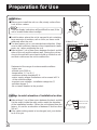
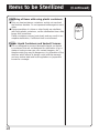
●Only use Type 1 borosilicate glass containers and do not
overload the stainless baskets. Do not squeeze bottles ag-
ainst each other.
●Place items that might entrap the water steam, such as bo-
wls or pitchers, upside down or on edge so they will be ste-
rilized properly.
●Place sterilizing glass containers such as beakers, triangu-
lar flasks, test tubes and the containers upside down or on
edge.
Placing glass containers upright makes it harder for the st-
eam to reach the bottom and can result in incomplete ster-
ilization.
Sterilizing of glass containers
Items to be Sterilized
Salt
water Strong
acids Strong
alkali
After
Sterilization
Before
Sterilization
Vented Test
Tube Cape
Cotton
Stoppers
Disposable
Vented Closures

18
●Only use heat resistance containers and do not overload
the stainless baskets. Do not squeeze bottles against each
other.
●If large quantities of culture or other liquids are sterilized
with using plastic containers, set the sterilization time a little
longer than usual time.
Plastic containers convey heat slowly and can result in inc-
omplete sterilization, if sufficient time is not allowed.
Sterilizing of items with using plastic containers
●It is not designed to process flammable liquids nor liquids
in containers that are not designed for sterilization (e.g.co-
ntainers having screw caps, non vented stoppers, etc.) ,
therefore doing so may be dangerous. Any alteration of the
sterilizer which affects its design could void the warranty
and may violate state and local regulations or jeopardize
insurance coverage.
Proper Liquid Containers and Vented Closures
Made of
plastic
Items to be Sterilized (Continued)

19
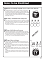
2. If media spills are discovered in the bottom of
chamber, proceed as follows:
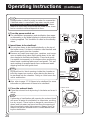
1. Exhaust tank setup
(1)
Remove the exhaust tank from the main unit and, from
the opening at the top, fill the tank with water up to the
LOW level mark.
(2)
Insert the exhaust hose that is connected to the interior
of the main unit into the opening at the top of the tank.
Push it in securely until the gasket is firmly engaged.
(3)
Load the exhaust tank into the main unit with taking
care the exhaust hose not to bend or twist.
3. Pour water for evaporation into the chamber.
(1)
Turn the handle counterclockwise until it stops. Open the
door with turning the arm counterclockwise.
(2)
Close the drain valve.
(3)
Pour in water unit the top edge of the water level fitting on
the heater cover is covered. The level of water will be lower
after each sterilizing cycle, therefore this water must be rep-
lenished.
Pour water for evaporation
MLS-3020U units : 2 liters
MLS-2420U units : 1.5 liters.
Supplementary note
Starting Operation
Turning the gasket only one direction during insertion can
cause the hose to become twisted and possibly lead to
malfunctions.
Turn the gasket alternately to the left and right when
inserting it.
Note
Chamber should be cleaned daily when processing
media. See page 29 (Maintenance and care) for
cleaning.
Note
The amount of water in the exhaust tank increases in
every operation of sterilizer. If the water reaches the HIGH
level mark, discard this water and pour new water up to
the LOW mark. Do not try to pull the tank out from the
main unit, if the exhaust hose is still attached.
Note
Operating Instructions
Gasket
Exhaust hose
Insert, turning
altemately
left and right
Sterilization water
Heater cover
Water level
Water level
indicator

20
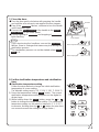
6. Close the exhaust knob.
●Close the exhaust knob by turning it clockwise as far as it
will go.
4. Turn the power switch on.
●The sterilization temperature and sterilization time appe-
ar alternately on the digital display to indicate that power
is being supplied. This condition is called as the standby
status.
5. Insert items to be sterilized.
●Do not place items to be sterilized directly on the top of
the heater cover. Put them in stainless steel baskets and
place them gently into the chamber.
●Remove any caps from empty jars, canisters, and nonpo-
rous containers and place them upside down in the stai-
nless basket to facilitate sterilization. Place hard goods
(i.e.metallic instruments) on the bottom when processing
mixed loade combining fabrics and hard goods. This pre-
vents wetting of wrapped packs from condensed water
dripping from the hard goods load.
●Also refer to page 17-18 (Items to be sterilized) for more
infomation on placement of items to be sterilized.
Be careful not to block openings inside the chamber or
inflict the impact on sensors, when placing the items to
be sterilized into the chamber. Doing so could cause the
unit to malfunction.
Performing of sterilization with opening the exhaust knob
will cause all water for sterilization to evapoirate, resulting
in a dry scorch. There is also a danger to cause burns, if
steam and hot water are forced out from the opening of
the exhaust tank under high pressure. Always check to
make sure that the exhaust knob is cloded before start-
ing the sterilization.
Note
Note
Distilled water is ideal for using as water for evaporation.
If distilled water is unavailable, tap water may be used.
Never use well water, saltwater or hard water. If these
water are used, they could cause the inside of the cham-
ber to corrode or mineral deposits to form.
Note
Operating Instructions (Continued)
CLOSEOPEN
Exhaust knob
Turn
EXHAUST
Sensor
Openings
Openings
La page est en cours de chargement...
La page est en cours de chargement...
La page est en cours de chargement...
La page est en cours de chargement...
La page est en cours de chargement...
La page est en cours de chargement...
La page est en cours de chargement...
La page est en cours de chargement...
La page est en cours de chargement...
La page est en cours de chargement...
La page est en cours de chargement...
La page est en cours de chargement...
La page est en cours de chargement...
La page est en cours de chargement...
La page est en cours de chargement...
La page est en cours de chargement...
-
 1
1
-
 2
2
-
 3
3
-
 4
4
-
 5
5
-
 6
6
-
 7
7
-
 8
8
-
 9
9
-
 10
10
-
 11
11
-
 12
12
-
 13
13
-
 14
14
-
 15
15
-
 16
16
-
 17
17
-
 18
18
-
 19
19
-
 20
20
-
 21
21
-
 22
22
-
 23
23
-
 24
24
-
 25
25
-
 26
26
-
 27
27
-
 28
28
-
 29
29
-
 30
30
-
 31
31
-
 32
32
-
 33
33
-
 34
34
-
 35
35
-
 36
36


Phcbi MLS-2420U Mode d'emploi
- Taper
- Mode d'emploi
- Ce manuel convient également à
dans d''autres langues
Documents connexes
Autres documents
-
Midmark M9-041 Manuel utilisateur
-
Midmark M9/M9D, M11 Self-Contained Steam Sterilizer (-040 through -042) Mode d'emploi
-
Midmark M9/M11 Self -Contained Steam Sterilizer (-043) Mode d'emploi
-
Midmark M3 Steam Sterilizer Mode d'emploi
-
-
-