Modern Forms PD-52718 Marimba Mode d'emploi
- Taper
- Mode d'emploi

Modernforms
www.modernforms.com
Phone (800) 526.2588 • Fax (800) 526.2585
Headquarters/Eastern Distribution Center
44 Harbor Park Drive • Port Washington, NY 11050
Phone (516) 515.5000 • Fax (516) 515.5050
Western Distribution Center
1750 Archibald Ave • Ontario, CA 91761
Phone (800) 526.2588 • Fax (800) 526.2585
Modernforms retains the right to modify the design of our products at any time as part of the company's continuous improvement program. MAY, 2014
INSTALLATION INSTRUCTION
MARIMBA
PD-52718
WARNING
IMPORTANT: NEVER attempt any work without shutting o the electricity.
- Read all instructions before installing.
- System is intended for installation by a qualied electrician in accordance with the National Electrical Code and local
regulations.
- Go to the main fuse box, or circuit breaker. Place the main power switch in the “OFF” position and unscrew the fuse(s) or
switch ”OFF” the circuit breaker switch(es) that control the power to the xture or room that you are working on.
- Place the wall switch in the “OFF” position.
CAUTION
- All parts must be used as indicated in these instructions. Do not substitute any parts, leave parts out, or use any parts
that are worn out or broken. Failure to follow this instruction could invalidate the ETL/CETL listing of this xture.
CAUTION When handling the xture, do not apply pressure to the LEDs. Hold the xture by the base only.
AVERTISSEMENT
IMPORTANT : Coupez l’électricité avant TOUTE manipulation.
- Lisez toutes les instructions avant d’installer.
- Système est destiné à être installé par un électricien qualié en conformité avec le code national de l’électricité et les
règlements locaux.
- Accédez au panneau central de disjoncteurs ou de fusibles de votre demeure et placez l’interrupteur principal en posi
tion d’arrêt (« OFF »).
- Placez l’interrupteur mural en position d’arrêt (« OFF »).
MISE EN GARDE
- Toutes les pièces doivent être utilisées tel qu’il est indiqué dans ces instructions. Ne remplacez pas les pièces, n’en
laissez pas de côté et ne les utilisez pas si elles sont usées ou brisées. Le non-respect de ces instructions peut annuler
l’homologation ETL/CETL du luminaire. MISE EN GARDE Ors de la manipulation de l’appareil, ne pas appliquer de pression
à la LED, tenir l’appareil par la seule base.
ADVERTENCIA
IMPORTANTE: NUNCA intente hacer trabajos sin desconectar el suministro eléctrico.
- Lea y comprenda todas las instrucciones e ilustraciones por completo antes de proceder con el ensamblaje e insta
lación de esta lámpara.
- Sistema está disenado para ser instalado por un electricista calicado, de acuerdo con el código eléctrico nacional
y las normas locales.
- Diríjase a la caja de fusibles o a la caja del interruptor de circuito principal en su hogar. Coloque el interruptor de ali
mentación principal en la posición “OFF” (APAGADO).
- Coloque el interruptor de la pared en la posición “OFF” (APAGADO).
PRECAUCIÓN
- Todas las piezas deben usarse como lo indican estas instrucciones. No reemplace las piezas, noomita piezas durante la
instalación ni utilice piezas gastadas o rotas. El incumplimiento de esta indicación podría invalidar la calicación
ETL/CETL esta lámpara. PRECAUCIÓN Al manipular el aparato, no aplique presión a los LED, mantenga el aparato en la
base sólo.
HARDWARE C1 E1 B1

Modernforms
www.modernforms.com
Phone (800) 526.2588 • Fax (800) 526.2585
Headquarters/Eastern Distribution Center
44 Harbor Park Drive • Port Washington, NY 11050
Phone (516) 515.5000 • Fax (516) 515.5050
Western Distribution Center
1750 Archibald Ave • Ontario, CA 91761
Phone (800) 526.2588 • Fax (800) 526.2585
Modernforms retains the right to modify the design of our products at any time as part of the company's continuous improvement program. MAY, 2014
PREPARATION
1. Shut o the power at the circuit breaker and remove
existing xture, including the mounting hardware.
2. Carefully unpack your new xture and lay out
all the parts on a clear area. Be careful not to lose
any small parts necessary for installation.
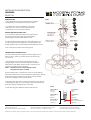
MOUNTING THE FIXTURE (FIG.1)
3. Secure the mounting plate (D1) to the junction box
(A1) using junction box screw (E1). The side of the
mounting plate marked “GND” must face out.
4. Adjust the xture wire length by pushing the gripper (J1)
on the canopy and pulling the wire, as desired. Make sure
keeping 3 xture wires same length and whole xture is level.
5. Re-set the strain relief near the wiring holes.
CONNECTING THE WIRES (FIG.2)
6. Connect the transformer input wires with supply wires as
shown in Fig. 2, making sure that all wire connectors (C1)
are secured.
7. Cut the xture wires which marked “24V AC”, Keep
enough length at least 6”. Connect with the transformer
output wires (red). Make sure that all wire connectors are
secured. Cut another wire and leave it.
Notes: The xture wires are braided two layers.
Stripped two layers carefully.
If your outlet box has a ground wire, connect it to the xture’s
ground wire. Otherwise, connect the xture’s ground wire directly
to the mounting plate (D1) using the green screw provided.
Tuck wires carefully inside the junction box.
8. Align the key holes on the canopy (F1) with the screws (B1) on
mounting plate (D1), place the canopy (F1) over the mounting
plate (D1). Twist it and tighten the screws (B1).
9. Twist lock the glass diuser (I1) into the shade (H1).
INSTALLATION INSTRUCTION
MARIMBA
PD-52718
FIG.2
Fixture Wires
Black or
Smooth
Fixture Wires
White or
Ribbed
Fixture Wires
Bare Copper
(Ground)
House Wires
Black
(Hot)
House Wires
White
(Neutral)
House Wires
Green or Bare Copper
(Ground)
F1
C1
D1
B1
E1
G1
J1
H1
I1
FIG.1

1
modernforms.com
Phone (800) 526.2588
Fax (800) 526.2585
Headquarters/Eastern Distribution Center
44 Harbor Park Drive
Port Washington, NY 11050
Central Distribution Center
1600 Distribution Ct
Lithia Springs, GA 30122
Western Distribution Center
1750 Archibald Avenue
Ontario, CA 91760
INSTALLATION INSTRUCTION
PD-52734
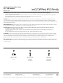
Wire Connector
Qty: 3 pcs + 1 Extra
63000122
Junction Box Screw
Qty: 2 pcs + 1 Extra
7606020251
#8−32×1
Zinc Plating
Mounting Screw
Qty: 1 Extra
7601030151
5/32−32×5/8
Nickel Plating
A B C
!"#$%&'"(')*+,+-.'+/+0.*102/'34(056'+-37*+'+/+0.*101.8'423'9++-'.7*-+:'(;'2.'.4+'01*071.'9*+25+*'9+<(*+'9+=1--1-=>'
• Read all instructions before installing.
• System is intended for installation by a licensed electrician in accordance with the National Electrical Code (NEC) and local regulations.
• When handling the xture, do not apply pressure to the LEDs. Hold the xture by the base only.
• Retain installation instructions for future maintenance reference.
%#%?&'All parts must be used as indicated in these instructions. This product is designed for use only with the supplied parts and/or
accessories designated for use by Modern Forms. Substitution of parts or accessories not designated for use with this product by Modern
Forms could result in personal injury or property damage, and will void the warranty. Contact an authorized dealer or the manufacturer if any
parts are damaged or missing.
@#%"%% '%$"&'Coastal conditions may cause mineral and residue build-up on the xture. We recommend that customers in coastal
areas clean all external surfaces of the xture once every two weeks with a wet cloth.
@#A'%'?&'B(7*'C,1.+*'.(7.'04(0'C/+0.*1D7+6'2337*+EF,(73'D7+'/+':13G(-0.+7*'3(1.'H13'4(*3'.+-31(-'2,2-.':+'0(HH+-0+*>'
• Lisez toutes les instructions avant l’installation.
• Le système doit être installé par un électricien licensié conformément au code national de l’électricité (NEC), et également aux
règlements locaux.
• Lors de la manipulation du luminaire, n’appuyez pas sur les LED. Tenez-le uniquement par la base.
""%"#$%&'Toutes les pièces doivent être utilisées comme indiqué dans ces instructions. Ce produit est conçu pour être utilisé seulement
avec les pièces et/ou accessoires fournis pour être utilisés avec les produits Modern Forms. Remplacer des pièces ou accessoires non conçus
pour ce produit Modern Forms pourrait causer des dommages corporels ou matériels et pourrait également causer l’annulation de la
garantie. Veuillez contacter un revendeur autorisé ou le fabricant si des pièces manquent ou sont endommagées.
%$"'I%""#%&''Les conditions côtières peut causer une accumulation de minéraux et de résidue sur le luminaire. Nous recommendons
aux clients qui resident dans les zones côtières de nettoyer toutes les surfaces externes du luminaire une fois toutes les deux semaines avec
un chion humide.

2
modernforms.com
Phone (800) 526.2588
Fax (800) 526.2585
Headquarters/Eastern Distribution Center
44 Harbor Park Drive
Port Washington, NY 11050
Central Distribution Center
1600 Distribution Ct
Lithia Springs, GA 30122
Western Distribution Center
1750 Archibald Avenue
Ontario, CA 91760
PREPARATION
1.
2.
parts on a clear area. Be careful not to lose any small
parts necessary for installation.
CONNECTING THE WIRES (Fig. 1)
3.
4. Secure the mounting plate to the junction box using
junction box screws (B1). The side of the mounting
plate marked “GND” must face out.
5.
grippers on the canopy and pulling the wire as desired.
6. Re-set the strain relief near the wiring holes.
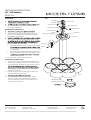
MOUNTING THE FIXTURES (Fig. 2)
7. Connect the transformer input wires with supply
wires as shown in Fig. 2 , making sure that all wire
connectors (A1) are secured. If your outlet box has a
to the mounting plate using the green screw provided.
Tuck wires carefully inside the junction box.
8. Place the canopy over the mounting plate. Twist it and
tighten the mounting screws (C1).
9.
Mounting Screw
Ground Wire Screw
Ground Wire
Strain Relief
Canopy
Shade
Wire Connector
Junction Box Screw
Input
Transformer x3 (Output)
Glass
(RPL-GLA-52734-GL)
(RPL-GLA-52734-GL)
Supply Wire
Junction Box
Mounting Plate
Cable-gripper
C1
A1
B1
Fixture Wires
Black or
Smooth
Fixture Wires
White or
Ribbed
Fixture Wires
Bare wire
(Ground)
House Wires
Black
(Hot)
House Wires
White
(Neutral)
House Wires
Green or Bare Copper
(Ground)
Fig. 2 Wiring
INSTALLATION INSTRUCTION
PD-52734
0RGHUQ)RUPVUHWDLQVWKHULJKWWRPRGLI\WKHGHVLJQRIRXUSURGXFWVDWDQ\WLPHDVSDUWRIWKHFRPSDQ\VFRQWLQXRXVLPSURYHPHQWSURJUDP
y small
x using
ed.
x has a
vided.
wist it and
Mounting Screw
Ground Wire Screw
Ground Wire
Strain Relief
Canopy
Shade
Wire Connector
Junction Box Screw
Input
Transformer x3 (Output)
Glass
(RPL-GLA-52734-GL)
(RPL-GLA-52734-GL)
Supply Wire
Junction Box
Mounting Plate
Cable-gripper
C
A
B
FIG. 1
opper
Cable-gripper
Metal ring
4. Secure the mounting plate to the junction box using
junction box screw (B1). The side of themounting plate
marked “GND” must face out.
7. Connect the transformer input wires with supply wires as
shown in Fig. 2, making sure that all wire connectors (C1)
are secured. If your outlet box has a ground wire, connect
using the green screw provided. Tuck wires carefully
inside the junction box.
8. Place the canopy over the mounting plate. Twist it and
tighten the mounting screws (C1).
9.
wire length by pushing the cable gripper on the canopy
metal ring back to the cable gripper.
a. Retract these wires close to a desirable length to within
the cable gripper to adjust more than 18” of wire length
is not desirable.
b. Warning: Shortening these cables without professional
helps or electronic background is not advisable. Any
warranty of the product.
6. Re-set the strain relief near the wiring holes.
on a clear area. Be careful not to lose any small parts
necessary for installation.
!!
""#$%
10. Please follow these if shortening the wire is needed.
Take note or take picture of how the wires are being
connected and label each wire clearly. Using the Fig. 3
as given below as reference.
&'

3
modernforms.com
Phone (800) 526.2588
Fax (800) 526.2585
Headquarters/Eastern Distribution Center
44 Harbor Park Drive
Port Washington, NY 11050
Central Distribution Center
1600 Distribution Ct
Lithia Springs, GA 30122
Western Distribution Center
1750 Archibald Avenue
Ontario, CA 91760
INSTALLATION INSTRUCTION
PD-52734
8"
8"
4" Fixture Wires
Black or
Smooth
Fixture Wires
White or
Ribbed
Fixture Wires
Bare wire
(Ground)
House Wires
Black
(Hot)
House Wires
White
(Neutral)
House Wires
Green or Bare Copper
(Ground)
!"#$%!
Driver
Input
Output
Black(L) White(N)
White(N)
White(N) White(N)
Black(L)
Black(L) Black(L)
Driver
Input
Output
Driver
Input
Output
!"&!%
-
 1
1
-
 2
2
-
 3
3
-
 4
4
-
 5
5


Modern Forms PD-52718 Marimba Mode d'emploi
- Taper
- Mode d'emploi
dans d''autres langues
Documents connexes
-
Modern Forms PD-41803L Cascade Mode d'emploi
-
-
-
-
-
-
-
-
-