Hilti UH 700 Manuel utilisateur
- Catégorie
- Marteaux rotatifs
- Taper
- Manuel utilisateur


1

2
3
4
5

6
7
8
9

10
11
12
13

14


*273762* 273762 English 1
Original operating instructions
1 Information about the documentation
1.1 About this documentation
• Read this documentation before initial operation or use. This is a prerequisite for safe, trouble-free
handling and use of the product.
• Observe the safety instructions and warnings in this documentation and on the product.
• Always keep the operating instructions with the product and make sure that the operating instructions
are with the product when it is given to other persons.
1.2 Explanation of symbols used
1.2.1 Warnings
Warnings alert persons to hazards that occur when handling or using the product. The following signal words
are used:
DANGER
DANGER !
▶Draws attention to imminent danger that will lead to serious personal injury or fatality.
WARNING
WARNING !
▶Draws attention to a potential threat of danger that can lead to serious injury or fatality.
CAUTION
CAUTION !
▶Draws attention to a potentially dangerous situation that could lead to personal injury or damage to the
equipment or other property.
1.2.2 Symbols in the operating instructions
The following symbols are used in these operating instructions:
Comply with the operating instructions
Instructions for use and other useful information
Dealing with recyclable materials
Do not dispose of electric equipment and batteries as household waste
1.2.3 Symbols in illustrations
The following symbols are used in illustrations:
These numbers refer to the illustrations at the beginning of these operating instructions.
The numbering reflects the sequence of operations shown in the illustrations and may deviate
from the steps described in the text.
Item reference numbers are used in the overview illustration and refer to the numbers used in
the key in the product overview section.
These characters are intended to specifically draw your attention to certain points when handling
the product.

2 English 273762 *273762*
1.3 Product-dependent symbols
1.3.1 Symbols on the product
The following symbols can be used on the product:
Wear a hard hat
Wear eye protection
Wear light respiratory protection
Wear ear protection
Wear protective gloves
Hammer drilling
Drilling without hammering, 1st gear
Drilling without hammering, 1st gear
Amps
Hertz
Volts
Watts
Alternating current
Double insulated
Revolutions per minute
If applied on the product, the product has been certified by this certification body for the US and
Canadian markets according to the applicable standards.
1.4 Product information
products are designed for professional users and only trained, authorized personnel are
permitted to operate, service and maintain the products. This personnel must be specifically informed about
the possible hazards. The product and its ancillary equipment can present hazards if used incorrectly by
untrained personnel or if used not in accordance with the intended use.
The type designation and serial number are printed on the rating plate.
▶Write down the serial number in the table below. You will be required to state the product details when
contacting Hilti Service or your local Hilti organization to inquire about the product.
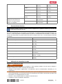
Product information
Hammer drill UH 700
Generation 01
Serial no.
2 Safety
2.1 General power tool safety warnings
WARNING Read all safety warnings, instructions, illustrations and specifications provided with this
power tool. Failure to follow all instructions listed below may result in electric shock, fire and/or serious injury.
Save all warnings and instructions for future reference.

*273762* 273762 English 3
The term "power tool" in the warnings refers to your mains-operated (corded) power tool or battery-operated
(cordless) power tool.
Work area safety
▶Keep work area clean and well lit. Cluttered or dark areas invite accidents.
▶Do not operate power tools in explosive atmospheres, such as in the presence of flammable
liquids, gases or dust. Power tools create sparks which may ignite the dust or fumes.
▶Keep children and bystanders away while operating a power tool. Distractions can cause you to lose
control.
Electrical safety
▶Power tool plugs must match the outlet. Never modify the plug in any way. Do not use any adapter
plugs with earthed (grounded) power tools. Unmodified plugs and matching outlets will reduce risk of
electric shock.
▶Avoid body contact with earthed or grounded surfaces, such as pipes, radiators, ranges and
refrigerators. There is an increased risk of electric shock if your body is earthed or grounded.
▶Do not expose power tools to rain or wet conditions. Water entering a power tool will increase the
risk of electric shock.
▶Do not abuse the cord. Never use the cord for carrying, pulling or unplugging the power tool. Keep
cord away from heat, oil, sharp edges or moving parts. Damaged or entangled cords increase the
risk of electric shock.
▶When operating a power tool outdoors, use an extension cord suitable for outdoor use. Use of a
cord suitable for outdoor use reduces the risk of electric shock.
▶If operating a power tool in a damp location is unavoidable, use a residual current device (RCD)
protected supply. Use of an RCD reduces the risk of electric shock.
Personal safety
▶Stay alert, watch what you are doing and use common sense when operating a power tool. Do
not use a power tool while you are tired or under the influence of drugs, alcohol or medication. A
moment of inattention while operating power tools may result in serious personal injury.
▶Use personal protective equipment. Always wear eye protection. Protective equipment such as a
dust mask, non-skid safety shoes, hard hat or hearing protection used for appropriate conditions will
reduce personal injuries.
▶Prevent unintentional starting. Ensure the switch is in the off-position before connecting to power
source and/or battery pack, picking up or carrying the tool. Carrying power tools with your finger on
the switch or energising power tools that have the switch on invites accidents.
▶Remove any adjusting key or wrench before turning the power tool on. A wrench or a key left
attached to a rotating part of the power tool may result in personal injury.
▶Do not overreach. Keep proper footing and balance at all times. This enables better control of the
power tool in unexpected situations.
▶Dress properly. Do not wear loose clothing or jewellery. Keep your hair and clothing away from
moving parts. Loose clothes, jewellery or long hair can be caught in moving parts.
▶If devices are provided for the connection of dust extraction and collection facilities, ensure these
are connected and properly used. Use of dust collection can reduce dust-related hazards.
▶Do not let familiarity gained from frequent use of tools allow you to become complacent and ignore
tool safety principles. A careless action can cause severe injury within a fraction of a second.
Power tool use and care
▶Do not force the power tool. Use the correct power tool for your application. The correct power tool
will do the job better and safer at the rate for which it was designed.
▶Do not use the power tool if the switch does not turn it on and off. Any power tool that cannot be
controlled with the switch is dangerous and must be repaired.
▶Disconnect the plug from the power source and/or remove the battery pack, if detachable, from
the power tool before making any adjustments, changing accessories, or storing power tools.
Such preventive safety measures reduce the risk of starting the power tool accidentally.
▶Store idle power tools out of the reach of children and do not allow persons unfamiliar with the
power tool or these instructions to operate the power tool. Power tools are dangerous in the hands
of untrained users.
▶Maintain power tools and accessories. Check for misalignment or binding of moving parts,
breakage of parts and any other condition that may affect the power tool’s operation. If damaged,
have the power tool repaired before use. Many accidents are caused by poorly maintained power
tools.

4 English 273762 *273762*
▶Keep cutting tools sharp and clean. Properly maintained cutting tools with sharp cutting edges are
less likely to bind and are easier to control.
▶Use the power tool, accessories and tool bits etc. in accordance with these instructions, taking
into account the working conditions and the work to be performed. Use of the power tool for
operations different from those intended could result in a hazardous situation.
▶Keep handles and grasping surfaces dry, clean and free from oil and grease. Slippery handles and
grasping surfaces do not allow for safe handling and control of the tool in unexpected situations.
Service
▶Have your power tool serviced by a qualified repair person using only identical replacement parts.
This will ensure that the safety of the power tool is maintained.
2.2 Drill safety warnings
Safety instructions for all operations
▶Wear ear protectors when impact drilling. Exposure to noise can cause hearing loss.
▶Use the auxiliary handle(s). Loss of control can cause personal injury.
▶Hold the power tool by insulated gripping surfaces, when performing an operation where the
cutting accessory may contact hidden wiring or its own cord. Cutting accessory contacting a "live"
wire may make exposed metal parts of the power tool "live" and could give the operator an electric
shock.
Safety instructions when using long drill bits
▶Never operate at higher speed than the maximum speed rating of the drill bit. At higher speeds,
the bit is likely to bend if allowed to rotate freely without contacting the workpiece, resulting in personal
injury.
▶Always start drilling at low speed and with the bit tip in contact with the workpiece. At higher
speeds, the bit is likely to bend if allowed to rotate freely without contacting the workpiece, resulting in
personal injury.
▶Apply pressure only in direct line with the bit and do not apply excessive pressure. Bits can bend
causing breakage or loss of control, resulting in personal injury.
2.3 Additional safety instructions
Personal safety
▶Use the product and accessories only when they are in perfect working order.
▶Never tamper with or modify the product and accessories in any way.
▶Always hold the product with both hands on the grips provided. Keep the grips dry, clean and free from
oil and grease.
▶Always lead the supply cord and extension cord away from the product to the rear while working. This
helps to avoid tripping over the cord while working.
▶Take frequent breaks and do physical exercises to improve the blood circulation in your fingers. High
vibration during long periods of work can lead to disorders of the blood vessels and nervous system in
the fingers, hands and wrists.
▶Risk of injury by falling tools and/or accessories. Before starting work, check that installed accessories
are secure.
▶Wear eye protection, a hard hat and ear protection while the product is in use.
▶Keep the air vents clear at all times. Risk of burn injuries due to blocked air vents!
▶Dust produced by grinding, sanding, cutting and drilling can contain dangerous chemicals. Some
examples are: lead or lead-based paints; brick, concrete and other masonry products, natural stone
and other products containing silicates; certain types of wood, such as oak, beech and chemically
treated wood; asbestos or materials that contain asbestos. Determine the exposure of the operator and
bystanders by means of the hazard classification of the materials to be worked. Implement the necessary
measures to restrict exposure to a safe level, for example by the use of a dust collection system or by
the wearing of suitable respiratory protection. The general measures for reducing exposure include:
▶working in an area that is well ventilated,
▶avoidance of prolonged contact with dust,
▶directing dust away from the face and body,
▶wearing protective clothing and washing exposed areas of the skin with water and soap.
▶The product is not intended for use by debilitated persons who have received no special training. Keep
the product out of reach of children.
▶Children are not permitted to play with the product and must be instructed accordingly.

*273762* 273762 English 5
Electrical safety
▶Check the product’s supply cord at regular intervals and have it replaced by a qualified specialist if found
to be damaged. If the power tool’s supply cord is damaged it must be replaced with a specially-prepared
and approved supply cord available from Hilti Customer Service. Check extension cords at regular
intervals and replace them if found to be damaged. Do not touch the supply cord or extension cord if
it is damaged while working. Unplug the supply cord from the power outlet. Damaged supply cords or
extension cords present a risk of electric shock.
▶Before beginning work, check the working area for concealed electric cables or gas and water pipes.
External metal parts of the product could give you an electric shock or cause an explosion if you
accidentally damage an electric cable or a gas or water pipe.
▶Switch the electric tool off and unplug the supply cord in the event of an interruption in the electric supply
in order to avoid inadvertent restarting when the power returns.
▶Dirty or dusty products that have been used frequently for work on conductive materials should be
checked at regular intervals by Hilti Service. Dust, especially dust from conductive materials, or
dampness on the surface of the product can, under unfavorable conditions, lead to electric shock.
Power tool use and care
▶Secure the workpiece. A workpiece clamped in a vice or secured by some other clamping devices is
more secure than when held only by hand.
▶Wear protective gloves when changing accessory tools as they get hot during use.
3 Description
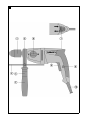
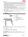
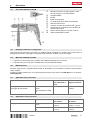
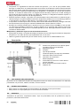
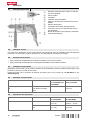
3.1 Product overview 1
@Drill chuck (keyless chuck or keyed chuck)
;Side handle
=sleeve
%Depth gauge
&Locking screw for depth gauge
(Function selector switch
)Forward / reverse switch
+Control switch with electronic speed control
§Lock button for continuous operation
/Supply cord
3.2 Intended use
The product is a hand-held, corded hammer drill. It is suitable for hammer drilling, drilling, screwdriving and,
under certain circumstances, stirring/mixing.
3.3 Possible misuse
• This product is not suitable for working on hazardous materials.
• This product is not suitable for working in a damp environment.
3.4 Items supplied
Hammer drill, side handle, depth gauge, chuck key, dust cap, operating instructions
Other system products approved for use with this product can be found at your local Hilti Store or at:
www.hilti.group

6 English 273762 *273762*
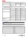
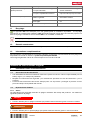
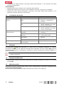
3.5 Application with hammer action
Application with hammer action Tool type Dimensions
1st gear/2nd gear
Dimensions, ham-
mer drilling
Hammer drilling in masonry Cylindrical-shank drill
bits
with carbide cutting
edge
— ≤ 16 mm
(≤ 0.6 in)
3.6 Applications without hammer action
Applications Tool type Dimensions
1st gear
Dimensions
2nd gear
Drilling in metal Cylindrical-shank drill
bits
≤ 13 mm
(≤ 0.5 in)
1.5 mm … 8 mm
(0.06 in … 0.3 in)
Stepped drill bits ≤ 35 mm
(≤ 1.4 in)
≤ 8 mm
(≤ 0.3 in)
Drilling in wood Twist drill bits ≤ 30 mm
(≤ 1.2 in)
≤ 30 mm
(≤ 1.2 in)
Forstner bits ≤ 45 mm
(≤ 1.8 in)
≤ 40 mm
(≤ 1.6 in)
Hole saws ≤ 80 mm
(≤ 3.1 in)
≤ 40 mm
(≤ 1.6 in)
Auger bits ≤ 30 mm
(≤ 1.2 in)
—
Spade bits (not self-
tapping)
≤ 40 mm
(≤ 1.6 in)
≤ 40 mm
(≤ 1.6 in)
Mixing emulsion paint
thin cement mortar,
tile adhesive,
gypsum plaster with mixing pad-
dle
TE-MP 80 In 1st gear
recommended
—
TE-MP 110 In 1st gear
recommended
—
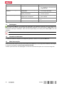
4 Technical data
For details of the rated voltage, current, frequency and/or input power, refer to the power tool’s
country-specific type identification plate.
If the tool is powered by a generator or transformer, the generator or transformer’s power output must be
at least twice the rated input power shown on the rating plate of the tool. The operating voltage of the
transformer or generator must always be within +5 % and -15 % of the rated voltage of the tool.
UH 700
Speed in 1st gear 900 /min
(15.0 Hz)
Speed in 2nd gear 2,500 /min
(41.7 Hz)
Maximum torque, 1st gear 80 Nm
(59 ftlbf)
Maximum torque, 2nd gear 29 Nm
(21 ftlbf)
Impact speed 40,000 Nm
(29,502 ftlbf)

*273762* 273762 English 7
UH 700
Diameter, chuck 1.5 mm … 13 mm
(0.06 in … 0.5 in)
Tightening torque for change of chuck 120 Nm
(89 ftlbf)
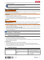
5 Use of extension cords
Using extension cords
WARNING
A damaged supply cord presents a hazard! Do not touch the supply cord or extension cord if damaged
while working. Disconnect the supply cord plug from the power outlet.
▶Check the appliance’s supply cord at regular intervals and have it replaced by a qualified specialist if
found to be damaged.
• Use only extension cords of a type approved for the application and with conductors of adequate gauge
(cross section). The power tool may otherwise suffer a drop in performance and the extension cord may
overheat.
• Check the extension cord for damage at regular intervals.
• Replace damaged extension cords.
• When working outdoors, use only extension cords that are approved and correspondingly marked for
this application.
Information on recommended minimum conductor cross-sections and cable lengths is accessible via
a link, in the form of a QR code, at the end of this document.
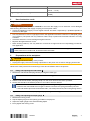
6 Preparations at the workplace
CAUTION
Risk of injury! Inadvertent starting of the product.
▶Unplug the supply cord before making adjustments to the power tool or before changing accessories.
Observe the safety instructions and warnings in this documentation and on the product.
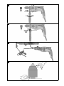
6.1 Fitting and adjusting the side handle 2
1. Release the side handle clamping band by turning the handle grip.
It is essential to ensure that the sleeve is fitted in the grip of the side handle.
2. Slide the side handle holder (clamping band) over the chuck and into the recess provided.
3. Set the side handle to the desired position in accordance with the detents.
Make sure that the ribs of the clamping band are snug in the grooves on the gearing section.
Otherwise the side handle will no longer be able to transfer the torques generated by the tool.
If the side handle slips because the drill bit stalls, check the positive lock/ribs on the gearing section.
4. Tighten the side handle holder (clamping band) by turning the handle grip.
6.2 Fitting and adjusting the depth gauge 3
1. Release the locking screw.
2. Slip the depth gauge into the opening provided for the purpose.
3. Adjust the depth gauge to the desired drilling depth.
4. Firmly tighten the locking screw.

8 English 273762 *273762*
6.3 Dust removal system (TE DRSS) 4
▶Install the dust extractor.
A dust removal system can be mounted on the depth gauge. The drilling fines are vacuumed off
by a vacuum cleaner. For more information on operation and use of the dust removal system, see
the separate operating instructions for the TE DRSS.
6.4 Removing quick-release chuck 5
1. Engage a 17 mm open-ended wrench on the flats of the drive spindle.
2. Engage a 19 mm open-ended wrench on the hexagon of the quick-release chuck.
3. Turn counter-clockwise with the 19 mm open-ended wrench.
▶The quick-release chuck is unscrewed from the drive spindle.
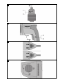
6.5 Installing quick-release chuck
1. Screw the quick-release chuck on to the drive spindle as far as it will go by hand.
2. Engage a 17 mm open-ended wrench on the flats of the drive spindle.
3. Engage a 19 mm open-ended wrench on the hexagon of the quick-release chuck.
4. Tighten the quick-release chuck.
Technical data
Tightening torque for change of chuck 120 Nm
(89 ftlbf)
6.6 Removing keyed chuck 6
1. Insert a length of hexagonal steel rod into the keyed chuck.
2. Use the chuck key to secure the hexagonal steel rod in the chuck.
3. Engage a 17 mm open-ended wrench on the flats of the drive spindle.
4. Engage the hexagonal steel rod with a suitable open-ended wrench.
5. Turn counter-clockwise with the open-ended wrench.
▶The keyed chuck is unscrewed from the drive spindle.
6.7 Installing keyed chuck
1. Insert a length of hexagonal steel rod into the keyed chuck.
2. Use the chuck key to secure a hexagonal steel rod in the chuck.
3. Screw the keyed chuck on to the drive spindle as far as it will go by hand.
4. Engage a 17 mm open-ended wrench on the flats of the drive spindle.
5. Engage the hexagonal steel rod with a suitable wrench.
6. Tighten the keyed chuck.
Technical data
Tightening torque for change of chuck 120 Nm
(89 ftlbf)
6.8 Removing accessory tool from quick-release chuck 7
1. Turn the locking sleeve of the quick-release chuck counter-clockwise.
The lock disengages automatically with an audible click.
2. Continue turning the sleeve until the accessory tool disengages.
6.9 Inserting accessory tool into quick-release chuck 8
1. Open the quick-release chuck until you can insert the shank of the accessory tool.
2. Clamp the accessory tool by turning the sleeve clockwise until the quick-release chuck automatically
engages.
▶Engagement is clearly audible as a series of clicks.

*273762* 273762 English 9
6.10 Inserting accessory tool into keyed chuck 9
1. Open the keyed chuck until you can insert the shank of the accessory tool.
2. Insert the accessory tool.
3. Close the keyed chuck by turning the gear ring.
4. Insert the chuck key into one of the holes in the keyed chuck.
5. Secure the accessory tool by turning the chuck key clockwise.
6. Remove the chuck key.
6.11 Removing accessory tool from keyed chuck 10
1. Insert the chuck key into one of the holes in the keyed chuck.
2. Turn the chuck key counter-clockwise to open the chuck.
3. Remove the accessory tool.
4. Remove the chuck key.
7 Types of work
WARNING
Damaged power cords are a safety hazard! If the supply cord or extension cord is damaged while work
is in progress, immediately disconnect the device and the cord from the electricity supply. Do not touch the
damaged part of the cord.
▶Regularly check all supply cords. Replace defective extension cords. Have damaged power cords
replaced by a qualified specialist.
Use of a ground fault circuit interrupter (residual current device, RCD) with a maximum tripping current of
30 mA is recommended.
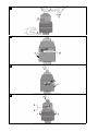
7.1 Switch sustained operation on and off 11
1. Press the control switch and hold it in this position.
2. Press and hold down the lockbutton.
3. Release the control switch.
4. Release the lockbutton.
5. To switch off continuous operation, press the control switch and then release it.
7.2 Control switch with electronic speed control
Speed can be controlled steplessly right up to maximum by varying how far the control switch is pressed in.
7.3 Setting forward or reverse rotation 12
CAUTION
Risk of damage Actuation while the tool is running may result in damage to the gearing.
▶Do not operate the forward / reverse switch while the motor is running.
▶Set the forward/reverse switch to the desired direction of rotation.
7.4 Hammer drilling 13
▶Set the function selector switch to hammer drilling: .
It might be necessary to turn the spindle slightly.
7.5 Drilling, 1st and 2nd gears 14
▶Set the function selector switch to position 1, “Drilling in first gear” or position 2, “Drilling in second gear”.
It might be necessary to turn the spindle slightly.

10 English 273762 *273762*
7.6 Mixing 14
▶Set the function selector switch to position 1, “Drilling in first gear".
It might be necessary to turn the spindle slightly.
7.7 Screwdriving 14
1. Set the forward/reverse switch to the desired direction of rotation.
2. Set the function selector switch to position 1, “Drilling in first gear” or position 2, “Drilling in second gear”.
It might be necessary to turn the spindle slightly.
8 Care and maintenance
WARNING
Electric shock hazard! Attempting care and maintenance with the supply cord connected to a power outlet
can lead to severe injury and burns.
▶Always unplug the supply cord before carrying out care and maintenance tasks.
Care
• Carefully remove stubborn dirt from the tool.
• Clean the air vents carefully with a dry brush.
• Use only a slightly damp cloth to clean the casing. Do not use cleaning agents containing silicone as
they can attack the plastic parts.
Maintenance
WARNING
Danger of electric shock! Improper repairs to electrical components may lead to serious injuries including
burns.
▶Repairs to the electrical section of the tool or appliance may be carried out only by trained electrical
specialists.
• Check all visible parts and controls for signs of damage at regular intervals and make sure that they all
function correctly.
• Do not operate the product if signs of damage are found or if parts malfunction. Have it repaired
immediately by Hilti Service.
• After cleaning and maintenance, fit all guards or protective devices and check that they function correctly.
To help ensure safe and reliable operation, use only genuine Hilti spare parts and consumables. Spare
parts, consumables and accessories approved by Hilti for use with the product can be found at your
local Hilti Store or online at: www.hilti.group.
9 Transport and storage
Transport
▶Do not transport this product with an accessory tool installed.
▶Make sure that the equipment is held securely throughout all transport operations.
▶After transporting, always check all visible parts and controls for signs of damage and make sure that
they all function correctly.
Storage
▶Always store this product with the electric supply cable unplugged from the electricity supply.
▶Store this product in a dry place, where it cannot be accessed by children or unauthorized persons.
▶After a long period of storage, always check all visible parts and controls for signs of damage and make
sure that they all function correctly.

*273762* 273762 Français 11
10 Troubleshooting
Trouble or fault Possible cause Action to be taken
Product does not start. Interruption in the electricity supply ▶Plug in another electric tool or
appliance and check whether it
works.
The supply cord or plug is defec-
tive.
▶Have the parts checked by a
trained electrical specialist and
replaced if necessary.
Electronic fault ▶Have the parts checked by a
trained electrical specialist and
replaced if necessary.
Product does not develop full
power.
The gauge (cross section) of the
extension cord conductors is inad-
equate.
▶Use an extension cord with
an adequate conductor cross
section.
The control switch is not fully
pressed.
▶Press the control switch as far
as it will go.
The drill bit makes no
progress.
Product has been set to reverse
rotation.
▶Set the product to forward
rotation.
Drill bit blunt or damaged. ▶Sharpen the drill bit or replace
it.
Drill bit does not rotate. Chuck not tightened securely. ▶Tighten the chuck.
11 Disposal
Most of the materials from which Hilti tools and appliances are manufactured can be recycled. The
materials must be correctly separated before they can be recycled. In many countries, your old tools,
machines or appliances can be returned to Hilti for recycling. Ask Hilti Service or your Hilti representative
for further information.
▶Do not dispose of power tools, electronic equipment or batteries as household waste!
12 Manufacturer’s warranty
▶Please contact your local Hilti representative if you have questions about the warranty conditions.
13 Further information
For more information on operation, technology, environment and recycling, follow this link:
qr.hilti.com/manual/?id=273762
This link is also to be found at the end of the operating instructions, in the form of a QR code.
Mode d'emploi original
1 Indications relatives à la documentation
1.1 À propos de cette documentation
• Lire intégralement la présente documentation avant la mise en service. C'est la condition préalablement
requise pour assurer la sécurité du travail et un maniement sans perturbations.
• Bien respecter les consignes de sécurité et les avertissements de la présente documentation ainsi que
celles figurant sur le produit.
• Toujours conserver le mode d'emploi à proximité du produit et uniquement le transmettre à des tiers
avec ce mode d'emploi.

12 Français 273762 *273762*
1.2 Explication des symboles
1.2.1 Avertissements
Les avertissements attirent l'attention sur des dangers liés à l'utilisation du produit. Les termes de
signalisation suivants sont utilisés :
DANGER
DANGER !
▶Pour un danger imminent qui peut entraîner de graves blessures corporelles ou la mort.
AVERTISSEMENT
AVERTISSEMENT !
▶Pour un danger potentiel qui peut entraîner de graves blessures corporelles ou la mort.
ATTENTION
ATTENTION !
▶Pour une situation potentiellement dangereuse pouvant entraîner des blessures corporelles ou des
dégâts matériels.
1.2.2 Symboles dans le manuel d'utilisation
Les symboles suivants sont utilisés dans le présent manuel d'utilisation :
Respecter le manuel d'utilisation
Pour des conseils d'utilisation et autres informations utiles
Maniement des matériaux recyclables
Ne pas jeter les appareils électriques et les accus dans les ordures ménagères
1.2.3 Symboles dans les illustrations
Les symboles suivants sont utilisés dans les illustrations :
Ces chiffres renvoient à l'illustration correspondante au début du présent manuel d'utilisation.
La numérotation détermine la séquence des étapes de travail dans l'image et peut se différencier
de celles des étapes de travail dans le texte.
Les numéros de position sont utilisés dans l'illustration Vue d’ensemble et renvoient aux numé-
ros des légendes dans la section Vue d'ensemble du produit.
Ce signe doit inviter à manier le produit en faisant particulièrement attention.
1.3 Symboles spécifiques au produit
1.3.1 Symboles sur le produit
Les symboles suivants peuvent être utilisés sur le produit :
Porter un casque de protection
Porter des lunettes de protection
Porter un masque respiratoire léger
Porter un casque antibruit
Porter des gants de protection
La page est en cours de chargement...
La page est en cours de chargement...
La page est en cours de chargement...
La page est en cours de chargement...
La page est en cours de chargement...
La page est en cours de chargement...
La page est en cours de chargement...
La page est en cours de chargement...
La page est en cours de chargement...
La page est en cours de chargement...
La page est en cours de chargement...
La page est en cours de chargement...
La page est en cours de chargement...
La page est en cours de chargement...
La page est en cours de chargement...
La page est en cours de chargement...
La page est en cours de chargement...
La page est en cours de chargement...
La page est en cours de chargement...
La page est en cours de chargement...
La page est en cours de chargement...
La page est en cours de chargement...
La page est en cours de chargement...
La page est en cours de chargement...
La page est en cours de chargement...
La page est en cours de chargement...
La page est en cours de chargement...
La page est en cours de chargement...
La page est en cours de chargement...
La page est en cours de chargement...
La page est en cours de chargement...
La page est en cours de chargement...
La page est en cours de chargement...
La page est en cours de chargement...
La page est en cours de chargement...
La page est en cours de chargement...
-
 1
1
-
 2
2
-
 3
3
-
 4
4
-
 5
5
-
 6
6
-
 7
7
-
 8
8
-
 9
9
-
 10
10
-
 11
11
-
 12
12
-
 13
13
-
 14
14
-
 15
15
-
 16
16
-
 17
17
-
 18
18
-
 19
19
-
 20
20
-
 21
21
-
 22
22
-
 23
23
-
 24
24
-
 25
25
-
 26
26
-
 27
27
-
 28
28
-
 29
29
-
 30
30
-
 31
31
-
 32
32
-
 33
33
-
 34
34
-
 35
35
-
 36
36
-
 37
37
-
 38
38
-
 39
39
-
 40
40
-
 41
41
-
 42
42
-
 43
43
-
 44
44
-
 45
45
-
 46
46
-
 47
47
-
 48
48
-
 49
49
-
 50
50
-
 51
51
-
 52
52
-
 53
53
-
 54
54
-
 55
55
-
 56
56


Hilti UH 700 Manuel utilisateur
- Catégorie
- Marteaux rotatifs
- Taper
- Manuel utilisateur
dans d''autres langues
- español: Hilti UH 700 Manual de usuario
- português: Hilti UH 700 Manual do usuário