La page est en cours de chargement...

WARNING:
The exclamation point inside an
equilateral triangle indicates the existen-
ce of internal components whose substi-
tution may affect safety.
The lightning and arrowhead symbol
warns about the presence of uninsula-
ted dangerous voltage.
To avoid fire or electrocution risk do not
expose the unit to rain or moisture.
To avoid electric shock, do not open the
unit. No user serviciable parts inside. In
the case of disfunction, have the unit
checked by qualified agents.
Class I device.
SAFETY
PRECAUTIONS AVERTISSEMENTS
SICHERHEITSHINWEISE
CAUTION
RISK OF ELECTRIC SHOCK
DO NOT OPEN
ACHTUNG!:
Das Ausrufezeichen innerhalb eines
Dreiecks weist auf den Enthalt interner
Bauteile hin, dessen Austausch
sicherheitsbedingt ist.
Das Blitzzeichen zeigt die Gegenwart
unisolierter gefährlicher Spannungen
an.
Um Brand oder elektrische Schläge zu
vermeiden, setzen Sie diese Einheit
keiner starken Luftfeuchtigkeit oder
Regen aus.
Damit elektrisch Schläge vermieden
werden, öffnen Sie diese Einheit nich.
Bei Bedarf von Reparaturen, wenden
Sie sich an qualifiziertes Personal.
Es handelt sich um ein Gerät der
Klasse I.
1
VORSICHT
GEFAHR EINES
ELEKTRISCHEN SCHLAGES.
NICHT ÖFFNEN!
RÈGLES DE SÉCURITÉ:
Le trinagle ponctué du point d’exclama-
tion central indique l’existence de com-
posants internes affectant la sécurité de
personnes non agrées par nos S.A.V..
Le symbole éclair indique la présence
de points électriques internes non iso-
lés.
Pour écarter tout risque d’incendie ou
d’électrocution, ne pas exposer l’appa-
reil à la pluie ni à l’humidité.
Afin d’éviter tout risque, ne pas ouvrir
l’appareil. Ne confier l’entretien de l’ap-
pareil qu’à du personnel technique qua-
lifié et agréé.
Appareil de Classe I.
ATTENTION
RISQUE DE CHOC ÉLECTRIQUE
NE PAS OUVRIR

0 Safety Precautions
1 General Information
1.1 Introduction
1.2 Main Characteristics
2 Controls: Where and What?
2.1 Front Panel
2.2 Rear Panel
3 Installation and Operation
3.1 Connections
3.1.1 Dual Mode (Stereo)
3.1.2 Parallel Mode
3.1.3 Bridge Mode (Mono)
3.2 Troubleshooting
4 Technical Specifications
4.1 Data
4.2 Electrical Schematic
©2000 by C.E. Studio-2 s.l.
P.I.Aldaya-C/ Sierra Perenxisa, nº 28
46960 Aldaya - Valencia - SPAIN
Phone: +34 96 127 30 54
Fax: +34 96 127 30 56
http://www.ramaudio.com
e-mail: [email protected]
N0326-143 QXPBUXDoc 5/00
RAM Audio
®
, CSP
™
, CRO
™
and ICL
™
are registered trademarks of C.E.
Studio-2 s.l.. All other names are trade-
marks of their respective companies.
0 Sicherheitsanweisungen
1 Allgemeine Anweisungen
1.1 Einleitung
1.2 Allgemeine Eigenschaften
2 Lokalisierung der Funktionen
2.1 Frontplatte
2.2 Rückseite
3 Anschluss- und Inbetriebnahme
3.1 Anschlüsse
3.1.1 Zweikanalmodus (Stereo)
3.1.2 Parallelmodus
3.1.3 Einkanalmodus (Bridge)
3.2 Problemlösung
4 Technische Spezifikationen
4.1 Technische Daten
4.2 Elektrische Diagramme
INHALTSVERZEICHNIS
INDEX
0 Avertissements
1 Informations Générales
1.1 Introduction
1.2 Caractéristiques générales
2 Emplacement des commandes et
leurs fonctions
2.1 Panneau avant
2.2 Panneau arrière
3 Installation et mise en route
3.1 Branchements
3.1.1 Fonctionnement en mode
stéréo
3.1.2 Fonctionnement en mode
paralléle
3.1.3 Fonctionnement en mode
mono (Bridge).
3.2 Dysfonctionnements éventuels
et dépannage.
4 Spécifications
4.1 Données téchniques
4.2 Schémas
TABLE DES
MATIÈRES
2

The RAM
®
BUX Series Power Amps
have been developped to meet the hig-
hest goals in the field of professional
power amplification. Their power, distor-
tion and dynamics figures place them
as reference in the industry.
The BUX Series incorporate unique
Absolute Protection Systems as the
CRO
™
, an immediate load disconnec-
tion system with an exclusive design
that excludes current in the output cir-
cuit relay, or the ICL
™
Clip-Limiter,
CSP
™
, ...
• Instantaneous High Flow Power
Supply.
• High Power Toroidal Transformer.
• Oversized Motorola
®
Output transis-
tors in the power modules.
• High Damping Factor.
• Unique Protection Systems: ICL
™
,
CSP
™
, CRO
™
...
• Dual, Bridge or Parallel operation
switch on rear panel.
• 3 U Rugged Steel Chassis.
• 10 mm thick, extruded and machined
duraluminum front panel.
• Twin Neutrik
®
XLR Connectors.
• Unobtrusive Gripping Handles in the
front panel.
• Slow Start System with circuit relay
based speaker protection.
• Back to front twin cooling fans.
• Electronic continuously variable fan
speed control.
• Usable voltage 170-245V (230V nomi-
nal) or 90-128V (120V nominal).
• 2 ohms continuous operation.
1.2 Main Characteristics
1.1 Introduction
Die RAM
®
- Endstufen der BUX-serie
sind dazu entwickelt worden, um den
höchsten Anforderungen im professio-
nellen Audiobereich entgegenzukom-
men. Ihre Eigenschaften bezüglich der
Leistung, Verzerrung und Dynamik
machen au der BUX-serie ein
Referenzprodukt.
Die BUX-serie enthält einzigartige
Schutzschaltungen, wie z.B. ein anti-clip
system (ICL
®
) oder das automatische
stromlose Abkopplungssytem zum
Schutz der Lautsprecher am
Ausgangsrelais (CRO
®
).
• Trafoeinheit mit sofortigem
Hochstrom.
• Hochleistungs-Toroidaltrafo.
• Leistungsmodule mit überdimensio-
nierten Motorola
®
-Transistoren.
• Hoher Dämpfungsfaktor.
• Einzigartige Schutzschaltungen (ICL
®
,
CSP
®
, CRO
®
, u.a.)
• Dual, Bridge and Parallel mode shal-
ter auf der Rückseite.
• Standardhöhe von zwei
Rackeinheiten.
• Die Frontplatte hat eine dicke von 10
mm, ist aus Duraluminium im
Sterangpressverfahren hergestellt und
wird im nachhein mechanisch bear-
beitet.
• Doppelte Neutrik
®
XLR - Stecker.
• Gestufte Einschalttechnik mit
Relaisschutz für die Lautsprecher
(Softstart)
• Lüfter mit stufenlos geregelter
Geschwindigkeit. Luftaustritt vorne.
• Elektronische Kontrolle der Lüfter.
• Voltage von 170-245V (230V nominal)
oder 90-128V (120V nominal).
• 2 ohms Anwendung.
1.2 Allgemeine Eigenschaften
1.1 Einleitung
General Information
Les amplificateurs de puissance RAM
®
BUX Series satisfont aux plus hautes
exigences des professionnels de la
sonorisation. Leurs caractéristiques de
puissance, distorsion et réponse transi-
toire font des amplificateurs de puissan-
ce BUX, de véritables outils de référen-
ce faisant rimer qualité de fabrication
avec pureté du son.
Les séries BUX sont dotées de plu-
sieurs systèmes de protection électroni-
ques brevetés, à l’instar du système
anti-clipping aservi (ICL
®
) sans influen-
ce sur l’écoute, du système de conne-
xion / déconnexion sécurisé pour les
HP, par absence de courant aux relais
(CRO
®
), ou de la tenue des court-
circuits permanents à pleine charge par
temporisation (CSP
®
).
• Grande capacité en courant instanta-
né.
• Transformateur torique surdimension-
né.
• Modules de puissance munis de tran-
sistors Motorola
®
amplement dimen-
sionnés.
• Très haut facteur d’amortissement.
• Protections de l’electronique et des
HP brevetées: ICL
®
, CSP
®
, CRO
®
...
• Conmutateur de mise en mode
Bridge, Dual ou Parallèle sur le pan-
neau arrière.
• Châssis extrêmement robuste, en
fonte d’acier.
• Panneau avant en dural, extrudé et
fraisé de 10mm, 3U standard, 19 pou-
ces.
• Connecteurs d’entrée type XLR
Neutrik
®
doublés (entrée-sortie).
• Temporisation à la mise sous tension.
• Refroidissement assuré par ventilation
forcée de l’arrière vers l’avant.
• Vitesse des ventilateurs asservie en
fonction de la température interne.
• Voltage de fontionement 170-245V
(230V nominal) ou 90-128V (120V
nominal).
• Fontionnement à 2 ohms continu.
1.2 Caractéristiques Générales
1.1 Introduction
Informations
Générales
Allgemeine
Anweisungen
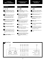
3

Lokalisierung der
Funktionen
See Figure
Signal attenuation level control
knobs: Permit independent control
of each channel’s attenuation (41
steps).
FAULT: This LED shows the circuit
relay on the output has open obe-
ying one or several protections’
orders from the amplifier: short cir-
cuit, low impedance, DC, start,...
TEMP: This LED shows temperatu-
re protection is active. Fault LED will
activate simultaneously indicating
loudspeaker disconnection.
SIGNAL: This LED indicates pre-
sence of signal at the inputs.
OK: LED indicating correct unit’s
function. Not lit in clipping situation
only.
CLIP: Clipping situation in the out-
puts’ signal. The LED will remain lit
for 200 ms regardless of real clip-
ping duration, to permit easy detec-
tion.
Main Power Switch: Connects the
amplifier’s current feed.
7
6
5
4
3
2
1
1
2.1 Front Panel
Siehe Fig.
Lautstärkeregler: diese ermögli-
chen, die Signalstärke am Ausgang
in 41 Stufen zu regeln.
FAULT: Diese LED-Anzeige leuchtet
auf wenn das Schutzrelais durch
irgendeine der Shutzschaltungen
ausgelöst worden ist (Kurzschluss,
niedrige Impedanz, Anwesenheit
von Gleichstrom, beim
Einschalten...)
TEMP: LED-Anzeige leuchtet wenn
eine der Überwärmungsfunktionen
eintritt. Gleichzeitig schaltet sich
auch die Anzeige “FAULT” ein.
SIGNAL: Wachanzeige des einkom-
menden Signals.
OK: Anzeige für die korrekte
Funktion dieser Einheit. Wird nur im
Fall von “clipping” gelöscht.
CLIP: Clip-Anzeige. Diese Anzeige
leuchtet 200 ms lang, unabhängig
von der realen Länge des clips.
Beleuchteter Hauptstromschalter:
Dieser Schalter schaltet die
Stromzuführung der Endstufe ein
und aus.
7
6
5
4
3
2
1
1
2.1 Frontplatte
Controls:
Where and What?
Voir Fig.
Atténuateurs de signal d’entrée
crantés: réglage du niveau d’entrée
indépendant sur chaque canal.
FAULT: signalisation par LED de la
coupure du signal de sortie.
TEMP: signalisation par LED de
temperature excessive. La LED de
signalisation FAULT s’activera
simultanément.
SIGNAL: indique la présence de
signaux d’entrée.
OK: signalisation d’un fonctionne-
ment correct. Cette LED s´éteint en
cas de clipping.
CLIP: signalisation de clipping en
sortie. L’allumage de cette LED se
maintient quelques instants pour
une meilleure visualition.
Power: Interrupteur de mise sous
tension.
7
6
5
4
3
2
1
1
2.1 Panneau Avant
Commandes et
Fonctions
4
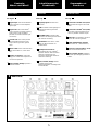
1
Front Panel

See Figure
Signal Input: Twin female Neutrik
®
XLR Connectors for the amplifier’s
signal input.
Signal Link: Twin male Neutrik
®
XLR Connectors for daisy chaining
input signal to other amplifiers
(parallel connected to female input
connectors).
Ground Link: This switch permits
connection/disconnection of the
amp’s internal ground to general
earth.
Mains Cable: Mains and earth main
feed (220V-240V AC / 110V-120V
AC).
Speaker connectors: Output bin-
ding posts and Neutrik
®
Speakon to
connect the speakers.
Dual / Parallel / Bridge Operation
Selection Switch.
6
5
4
3
2
1
2
2.2 Rear Panel
Siehe Fig.
Eingangssignal: Neutrik
®
-XLR
Buchsen.
LINK: Paralele XLR-Ausgänge zur
Zusammenschaltung mehrerer
Endstufen.
GROUND LINK: Ermöglicht den
Anschluss der Erdung an die Masse
der internen Schaltung.
Stromkabel: 220V-240 V / 110V-
120V AC Wechselstrom mit
Erdanschluss.
Dautsprecheranschluss:
Bananenstecker-Typ / Neutrik
®
Speakon Stecker zum Anschluss
externer Lautsprecher. Der
Anschluss erfolgt über Kabel mit
entfernter Isolierung.
Dual / Parallel / Bridge: Dieser
Schalter wechselt von
Zweikanaloperation zu Bridge oder
Parallel Modus.
6
5
4
3
2
1
2
2.2 Rückseite
Lokalisierung der
Funktionen
5
Controls:
Where and What?
Voir Fig.
Connecteurs Neutrik
®
XLR (feme-
lle) d’entrée des signaux de modu-
lation.
Connecteurs Neutrik
®
XLR (mâle),
sortie des signaux d’entrée pour la
mise en parallèle d’autres amplis.
GND Link: Commutateur de mise à
la terre de la masse générale.
Câble d’alimentation générale
(220V-240V AC / 110V-120V AC).
Bornes de sortie (Speakon / TP-6)
pour le branchement des HP.
Dual / Parallel / Bridge: Sélecteur
de mode pont (Bridge), parallele ou
stéréo.
6
5
4
3
2
1
2
2.2 Panneau Arrière
Commandes et
Fonctions
2
Rear Panel

The Power switch must always be on
the “Off” position before plugging the
amp to a properly earthed mains soc-
ket (220-240V AC).
The input signal fed to the amplifier can
be either balanced or un-balanced. The
drawing below describes both ways to
wire an XLR connector for the purpose.
Balanced Signal: Connect pin 1 to
Ground, pin 2 to Signal + (hot) and pin
3 to Signal - (cold).
Unbalanced Signal: Connect Pin 1 to
Ground, pin 2 to Signal and pin 3 to
Ground.
Important!: If a connection is done with
a un-balanced line and pin 3 on the
XLR is not connected to ground, a 6 dB
loss occurs in the line and only a quar-
ter of the amplifier power is produced.
The amplifier provides, for each chan-
nel, a female XLR Connector (Signal
Input) parallelled to a male XLR to daisy
chain several amplifiers with the same
signal line (LINK).
3.1 Connections
Bevor Sie diese Einheit an eine
SHUKO-Steckdose anschliessen, schal-
ten Sie den Hautstromschalter Aus.
Das Eingangssignal kann entweder
symmetrisch oder unsymmetrisch sein.
Der Anschluss wird gemacht wie folgt.
Symmetrisches Signal: Die Belegung
der XLR Pins ist folgende: 1-Masse, 2-
Positives Signal (hot), 3-Negatives
Signal (cold).
Asymetrisches Signal: Die Belegung
der XLR Pins ist folgende: 1-Masse, 2-
Signal, 3-Masse.
ACHTUNG! Wenn Sie ein
Asymetrisches Signal anschliessen und
Pin 3 nicht an Masse anschliessen,
erzeugt sich ein Verlust von 6dB (1/4
der Leistung der Endstufe) am usgangs-
signal.
Die Endstufe rechnet mit einer paralelen
XLR-Buchse, die zum Anschluss an
weitere Endstufen dient.
3.1 Anschluss
Installation and
Operation
Veillez à ce que l’interrupteur de mise
en service soit en position “Off” avant
de brancher l’appareil sur une prise
secteur avec mise à la terre (220V-
240V AC)
L’appareil peut fonctionner avec des
signaux symétriques ou asymétriques.
La figure ci-dessous indique le câblage
des connecteurs XLR pour les deux
cas.
Câblage Symétrique: souder la broche
1 à la masse, la broche 2 au point
chaud (+), et la broche 3 au point froid
(-).
Câblage Asymétrique: souder les bro-
ches 1 et 3 à la masse, et la broche 2
au signal.
Important: Si on effectue le branche-
ment d’un signal asymetrique sur le
connecteur XLR sans relier la broche 3
à la masse, une perte de 6dB sera
constatée , ce qui se traduira par une
perte du 75% de la puissance de sortie.
L’amplificateur est muni des connec-
teurs XLR mâle pour la mise en
parallèle de plusieurs amplificateurs
avec les mêmes signaux d’entrée.
3.1 Branchement
Installation et
mise en service
Anschluss und
Inbetriebnahme
Balanced Wiring
1- Ground
2- Signal +
3- Signal -
Unbalanced Wiring
1- Ground
2- Signal
3- Ground
6

Installation and
Operation
Installation et
mise en service
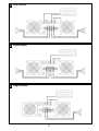
The amplifier can operate on three diffe-
rent configurations: DUAL, BRIDGE or
PARALLEL. The connections for the
three modes are different.
See Figure
- Switch “Off” the amp.
- Set the Mode Switch on the rear panel
to “DUAL”.
- Connect the signal lines to the female
XLR connectors on both channels.
- Connect the speakers’ lines to the
corresponding binding posts on the
amp respecting the polarity.
- Switch “On” the amp.
- Use the level control knob on the front
panel to adjust each channel indepen-
dently.
- Each signalling LED group will show
its corresponding channel status.
See Figure
- Operate as Dual Channel Mode with a
single signal input on Channel “A”.
See Figure
- Switch “Off” the amp.
- Set the Mode Switch on the rear panel
to “SINGLE” (Bridge).
- Connect a signal line to input female
XLR Channel “A”
.
- Connect the speaker line at the two
positive (Red) binding posts. Channel
“A” post becoming the positive in this
configuration. Alternatively use the
Channel A Speakon wired to +1 and
+2. In this way pin +1 is positive.
- Switch “On” the amp.
- Use both control knobs at the same
level to adjust the single amp’s output.
- Both signalling LED groups will show
the single channel status.
5
3.1.3 Single Channel Mode (Bridge)
4
3.1.2 Parallel Channel Mode
3
3.1.1 Dual Channel Mode (Stereo)
L’amplificateur peut fonctionner en
mode stéréo, parallèle ou ponté
(Bridge). Le branchement est différent
pour ces trois modes.
Voir Fig.
- Commuter l’interrupteur de mise en
service sur position “Off”.
- Sélectionner le mode Stéréo sur le
panneau arrière de l’appareil.
- Bancher les signaux d’entrée aux
fiches XLR femelles des deux canaux.
- Brancher les haut-parleurs sur les bor-
nes TP-6 en respectant les polarités.
- Commuter l’interrupteur de mise en
service sur position “On”.
- Utiliser les atténuateurs d’entrée en
face-avant pour régler le niveau de
sortie de chaque canal.
- Les indicateurs LED afficheront le
stade de chaque canal.
Voir Fig.
- Selectionner le mode Parallèle sur le
Panneau arrière de l'appareil. Utiliser
l'ampli comme en mode Dual mais
avec une seule entrée de signal au
Canal "A".
Voir Fig.
- Commuter l’interrupteur de mise en
service sur position “Off”.
- Sélectionner le mode Bridge sur le
panneau arrière de l’appareil.
- Brancher le signal modulation sur le
connecteur XLR (femelle) du Canal
“A”.
- Brancher les HP sur les bornes rouges
de sortie des deux canaux (bornes
TP-6). La borne rouge du canal “A” est
la borne + dans ce mode de fonction-
nement.
- Commuter l’interrupteur de mise en
service sur position “On”.
- Utilisser les deux atténuateurs d’en-
trée au méme niveau pour ajuster le
signal de sortie.
- Les deux rangées de LED afficheront
le niveau de sortie.
5
3.1.3 Mode Ponté Mono (Bridge)
4
3.1.2 Mode Parallèle
3
3.1.1 Mode Stéréo
Es gibt zwei Funktionsmöglichkeiten
dieser Endstufe: Dual, Parallel und
Bridge. Die Anschlüsse sind in beiden
Fällen verschieden:
Siehe Fig.
- Schalten Sie die Endstufe aus.
- Setzen Sie den Modusschalter auf der
Rückseite auf die Position “Dual”.
- Schliessen Sie beide Eingangssignale
an ihre entsprechenden XLR-Buchsen.
- Schliessen Sie beide Lautsprecher an
die entsprechenden Ausgänge an,
positiv an die rote Buchse.
- Schalten Sie die Endstufen ein.
- Benutzen Sie die Lautstärkereglung
der entsprechenden Kanäle um den
gewünschten Lautstärkepegel zu erre-
chen.
- Die LED-Anzeigen werden den Status
der beiden Kanäle angeben.
Siehe Fig.
- Gehen Sie wie im Dual-Channel-
Modus vor, indem aber ein einziges
Signal über den Kanal " A " einges-
peist wird.
Siehe Fig.
- Schalten Sie die Endstufe aus.
- Setzen Sie den Modusschalter auf der
Rückseite auf die Position “SINGLE”
(Bridge).
- Schliessen Sie das Eingangssignal an
die XLR-Buchse “A”
an.
- Schliessen Sie den Lautsprecher an
beide positiven Buchsen der beiden
Kanäle an, wobei positiv der roten
Buchsen des “A”- Kanals entspricht.
- Schalten Sie die Endstufen ein.
- Benutzen Sie die Lautstärkereglung
der beiden Kanäle um den gewünsch-
ten Lautstärkepegel zu errechen,
wobei beide Regler immer auf der
gleichen Position sein müssen.
- Die LED-Anzeigen werden den Status
des Ausgangkanals angeben.
5
3.1.3 Bridge Modus (Mono)
4
3.1.2 Parallel Modus
3
3.1.1 Dual Modus (Stereo)
7
Anschluss und
Inbetriebnahme
La page est en cours de chargement...

In the event of incorrect connection or
misfunctioning, the amp will activate
one or more of its LED to warn about
the problem.
Correct function.
CLIP: Clipping situation on the output.
No Signal: No Input Signal is reaching
the amp.
Overheating: The amplifier has rea-
ched the maximum operational tempe-
rature. Most common cause is: the nor-
mal air flow is blocked, accumulated
dirt, dust or object leaning against the
grill. Check and clean periodically.
Protections: Several causes can trig-
ger this LED, most common are:
- Short-circuit in the speakers’ line or in
the speakers themselves.
- Low Impedance: check speakers’ con-
nections or possible speaker disfunc-
tion.
- DC in the output: the protections are
activated to avoid damage to the spe-
akers, the unit must be sent in for
repair to a qualified technician.
- Delayed Start: As you switch on the
amp the output to the speakers is dis-
connected. After a few seconds the
amp will connect the speakers and
proceed with normal functioning.
3.2 Troubleshooting
Sollte sich irgendeine Fehlfunktion erge-
ben, wird diese durch die LED-Anzeigen
auf der Frontplatte gezeigt. Es gibt fol-
gende Möglichkeiten:
Korrektes Verhalten.
CLIP: Das Signal “clipt” am Ausgang.
Kein Signal: kein Eingangssignal
anwesend.
Überhitzung: Dies kann wegen der
Verschmutzung der Luftein- oder
Austritte geschehen. Es ist angebracht
diese von Zeit zu Zeit zu säubern.
Schutzschaltungen: Der Eingriff der
Schutzschaltungen kann sich durch fol-
gende Gründe auslösen:
- Kurzschluss: die Anschlusskabel oder
ggf. die Lautsprecher auf
Kurzschlüsse prüfen.
- Unangebrachte Impedanz: Die
Impedanz der Ausgänge ist zu niedrig.
Instalation auf Fehlanschlüsse testen
oder ggf. Lautsprecher auf Fehler prü-
fen.
- Gleichstrom: Die Schutzschaltung
greift ein, um die Zerstörung der
Lautsprecher zu vermeiden. Die
Endstufe muss von einem qualifizier-
tem Techniker überprüft werden.
- Soft Start: Während des
Inbetriebnahme der Endstufe werden
die Lautsprecher zeitlich ausgeschal-
tet, um einen möglichen Schaden zu
vermeiden. Nach einigen Sekunden
schaltet die Endstufe die Lautsprecher
automatisch ein.
3.2 Problemlösung
Installation and
Operation
En cas d’utilisation incorrecte ou de
dysfonctionnement, une ou plusieurs
LED seront allumées pour indiquer la
nature du problème.
Fonctionnement correct.
CLIP: signal de sortie en surmodulation.
Aucun Signal n’arrive à l’Ampli.
Surchauffe: l’amplificateur a atteint sa
plus haute température interne admissi-
ble. Le plus souvent ceci est dû à un
blocage ou à l’obturation des voies de
ventilation.
Protections: Plusieurs anomalies peu-
vent déclencher cet affichage. Les plus
courantes sont:
- Court-circuit sur ligne HP.
- Impédance trop basse pour un fonc-
tionnement à pleine puissance.
- Courant continu en sortie. Cette pro-
tection est activée pour ne pas
endommager les HP. Confier l’appareil
en SAV à un technicien agréé.
- Temporisation à la mise sous tension.
Les signaux de sortie sont atténués
pendant quelques secondes.
3.2 Dysfonctionnements éventuels
Installation et
mise en service
9
Anschluss und
Inbetriebnahme
La page est en cours de chargement...

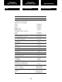
Technical
Specification Spécifications
Tecnische
Spezifikationen
4.2 Electrical Schematic 4.2 Schémas4.2 Elektrische Diagramme
11
La page est en cours de chargement...
-
 1
1
-
 2
2
-
 3
3
-
 4
4
-
 5
5
-
 6
6
-
 7
7
-
 8
8
-
 9
9
-
 10
10
-
 11
11
-
 12
12
-
 13
13


RAM BUX Mode d'emploi
- Catégorie
- Amplificateurs audio
- Taper
- Mode d'emploi
dans d''autres langues
- English: RAM BUX Operating instructions
- Deutsch: RAM BUX Bedienungsanleitung