La page est en cours de chargement...

LED.com
© 2023 Current Lighting Solutions, LLC. All rights reserved. Information and
specifications subject to change without notice. All values are design or typical
values when measured under laboratory conditions.
Page 1 of 4
(Rev 4/19/23)
IND607-Lumination-PVR-Series-ProLine-Volumetric-Retrofit-Installation-Guide_R01
Installation Guide
IND607 | DOC-2000313
Lumination® PVR Series
ProLine® Volumetric Retrot
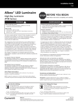
BEFORE YOU BEGIN
Read these instructions completely and carefully.
WARNING / AVERTISSEMENT
RISK OF ELECTRIC SHOCK
• Luminaire wiring and electrical parts may be damaged when
drilling for installation of LED retrot kit. Check for enclosed
wiring and components.
• LED Retrot Kit installation requires knowledge of luminaires
electrical systems. If not qualied, do not attempt installation.
Contact a qualied electrician.
• Install this kit only in luminaires that have the construction
features and dimensions shown in the photographs and/or
drawings and where the input rating of the retrot kit does
not exceed the input rating of the luminaire.
• To prevent wiring damage or abrasion, do not expose wiring
to edges of sheet metal or other sharp objects.
• Do not make or alter any open holes in an enclosure of
wiring or electrical components during kit installation.
• Suitable for damp locations.
RISQUES DE DÉCHARGES ÉLECTRIQUES
• Le câblage du luminaire ainsi que ses composantes électriques peuvent être
endommagés lors du perçage requis pour l’installation de l’ensemble de
mise à niveau à DEL. Vériez le câblage et les composants.
• L’installation de l’ensemble de mise à niveau à DEL requiert des
connaissances en système électrique d’éclairage. Si vous n’avez pas les
qualications adéquates, ne procédez pas à l’installation et contactez un
électricien qualié.
• N’installez cet ensemble de mise à niveau à DEL que sur des luminaires
ayant une construction et des dimensions indiquées sur les photos et
dessins et ce, seulement dans la mesure où les spécications d’entrées de
l’ensemble de mise à niveau à DEL n’excède pas les spécications d’entrée
du Luminaires dans lequel il sera installé.
• An de prévenir tout dommage ou abrasion aux ls électriques, évitez que
ceux-ci ne viennent en contact avec les bordures métalliques ou d’autres
ojets pointus.
• Ne laissez aucune ouverture dans le boitier ou le compartiment où se
trouvent les composants électriques.
• Convenient aux emplacements humides.
WARNING / AVERTISSEMENT
• Retrot kit may fall down if not installed properly, follow
installation instructions.
• This device is not intended for use with Emergency Exits.
• L’ensemble de mise à niveau à DEL peut tomber s’il n’est pas installé
correctement. Suivre les instructions d’installation.
• Cet appareil n’est pas conçu pour utilisation avec sortie de secours.
Save These Instructions
These instructions do not purport to cover all details or variations in components nor to provide for every possible contingency to be met in connection with
installation, operation or maintenance. Should further information be desired or should particular problem arise which are not covered sufciently for the
purchaser’s purpose, the matter should be referred to Current. Current does not claim liability for any installation not performed according to this guide or
not by a qualied electrician.
For Your Safety
Read and observe all CAUTIONS and WARNINGS shown throughout these instructions. Use this product only in the manner intended by the manufacturer. If
there are any questions or concerns, contact the manufacturer.

Product Title (XXX- Series) Installation Guide
LED.com
© 2023 Current Lighting Solutions, LLC. All rights reserved. Information and
specifications subject to change without notice. All values are design or typical
values when measured under laboratory conditions.
Page 2 of 4
(Rev 4/19/23)
IND607-Lumination-PVR-Series-ProLine-Volumetric-Retrofit-Installation-Guide_R01
The components have been properly packed to avoid damage during transit. Inspect the components to conrm there is no
physical damage. Do not install damaged components.
Components Supplied
• PVR Fixture (1)
• PVR Mounting Bracket (2)
• #8x1/2” Self-Drilling Screw (5)
• Green Ground Screw (1)
Installation
Prior to installation, disconnect all incoming power to
xture. Remove existing hardware (lens/lens frame,
parabolic louver, reectors/ballast covers, brackets, lamps/
lamp holders). Leave supply and grounding leads.
NOTE: Follow all federal and local regulations when
disposing of lamps and removed components.
1
Carefully unpack unit from its packaging. Properly inspect
for defects before installing. Wear work gloves to prevent
dirt and oil from being transferred to the luminaire.
2
Install PVR Mounting Bracket to each end of the xture by
sliding PVR Mounting Brackets between the xture and
T-grid, ensuring the mounting bracket is centered in the
xture. Secure the PVR Mounting Brackets to the xture
using 4 of the provided #8x1/2” self-drilling screws.
3
Install the PVR Fixture T-hinges into the
PVR Mounting Bracket cutouts.
4

LED.com
© 2023 Current Lighting Solutions, LLC. All rights reserved. Information and
specifications subject to change without notice. All values are design or typical
values when measured under laboratory conditions.
Page 3 of 4
(Rev 4/19/23)
IND607-Lumination-PVR-Series-ProLine-Volumetric-Retrofit-Installation-Guide_R01
Lumination® (PVR- Series) Installation Guide
Safety tether
Secure PVR xture to existing uorescent xture using
provided safety tether. Ensure safety tether loop is secured
around T-shaped tab in PVR Mounting Bracket.
5
Ensure power to the xture is turned off. Use a screw driver
to toggle the Lumen and CCT switches to the desired
settings.
6
Ground wire
Install grounding wire using provided
green ground screw (if existing hole
is available) OR #8x1/2” self-drilling
screw.
7
Secure swing door by locking latches
found on the end of the assembled PVR
Door.
9
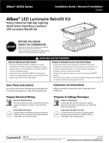
Diffuser panel
The diffuser panel may become loose during shipping or if the PVR luminaire is signicantly twisted during installation. It is important to ensure the
diffuser is completely engaged to avoid it falling out after installation is complete. If diffuser is loose, grasp the diffuser and gently squeeze together
the re-engage over lances.
10
Lance is engagedLance is disengaged
Squeeze
AC line
Connect the LED driver to AC line
using the provided ballast disconnect.
See “Electrical Connections” section
for wiring details.
8

LED.com
© 2023 Current Lighting Solutions, LLC. All rights reserved. Information and
specifications subject to change without notice. All values are design or typical
values when measured under laboratory conditions.
Page 4 of 4
(Rev 4/19/23)
IND607-Lumination-PVR-Series-ProLine-Volumetric-Retrofit-Installation-Guide_R01
Lumination® (PVR- Series) Installation Guide
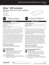
Using the provided quick-connect, connect the black (line) of the AC line to the black 120-277V or 347V wire and the white (neutral) wires
of the AC line to the white or red wires. Optional: If using a 0-10V dimming controller, connect matching-colored wires together.
Electrical Connections
Wiring Diagram
This device complies with Part 15 of the FCC Rules. Operation is subject to the following two conditions: (1) This device may not cause harmful interference,
and (2) this device must accept any interference received, including interference that may cause undesired operation.
CAN ICES-005(A)/NMB-005(A)
Note: This equipment has been tested and found to comply with the limits for a Class A digital device, pursuant to part 15 of the FCC Rules. These limits are
designed to provide reasonable protection against harmful interference when the equipment is operated in a commercial environment. This equipment
generates, uses, and can radiate radio frequency energy and, if not installed and used in accordance with the instruction manual, may cause harmful interfer-
ence to radio communications. Operation of this equipment in a residential area is likely to cause harmful interference in which case the user will be required
to correct the interference at their own expense.
Note: CONTACT FACTORY for details and limitations when seeking to incorporate this product with an emergency system other than Battery Backup.
120-277V
WHITE COMMON NEUTRAL
BLACK UNSWITCHED LINE
GROUND
GREY/PINK DIMMING 0-10V
VIOLET DIMMING (+)
PVR Fixture
347V
PVR Fixture
RED COMMON NEUTRAL 347V
BLACK UNSWITCHED LINE 347V
GROUND
GREY/PINK DIMMING 0-10V
VIOLET DIMMING (+)
EMERGENCY BYPASS OPTION
RED NORMAL NEUTRAL
NORMAL HOT
SELF-TEST INPUT (optional)
REMOTE-TEST INPUT (optional)
REMOTE-TEST INPUT (optional)
BLACK
WHITE/BLACK
WHITE/BLUE
WHITE/RED
Exterior Wires
PVR Fixture
DRIVER
VIOLET (1-10V+)
GRAY/PINK (1-10V –)
BLUE (LED –)
RED (LED+) TO LEDs
BLACK (LINE)
WHITE (NEUTRAL)
PVR POSITIVE LEAD
WHITE (NEUTRAL)
PVR CONTROLS AC LINE LEAD
PVR POSITIVE LEAD
RED (LOAD)
BLACK (LINE)
VIOLET (1-10V+)
GRAY/PINK (1-10V–)
CONTROLLER
/